POWER PLANT: One Napier Rapier air-cooled engine, rated at 395 hp
PERFORMANCE: 124 mph
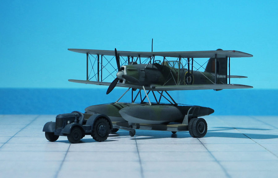
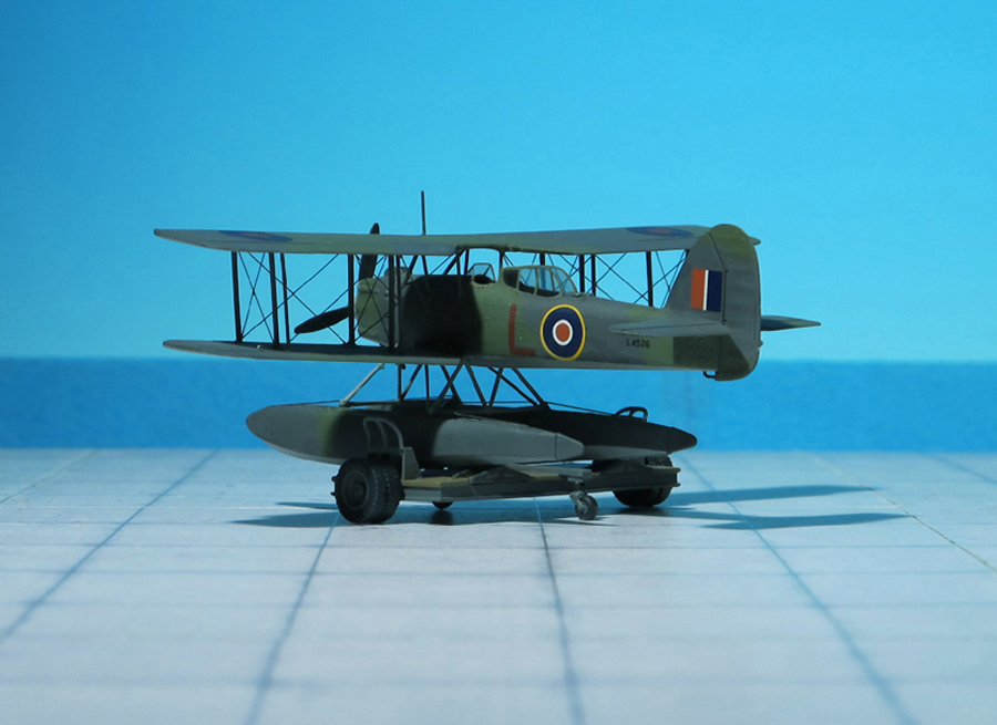
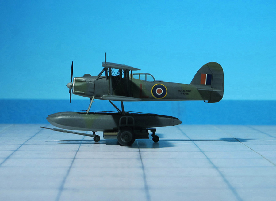
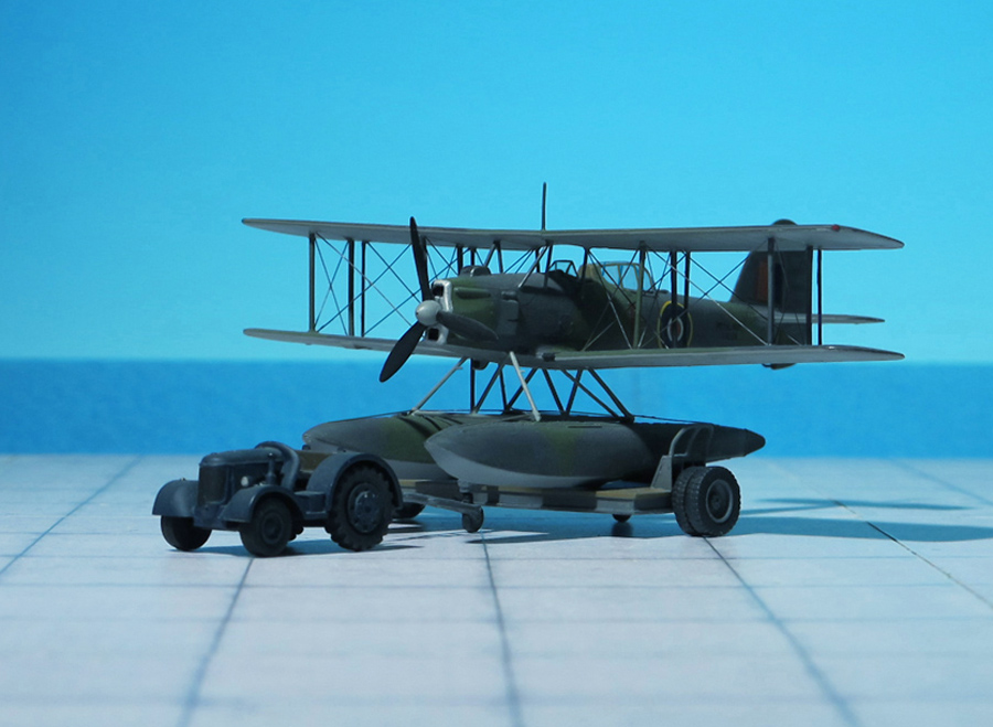
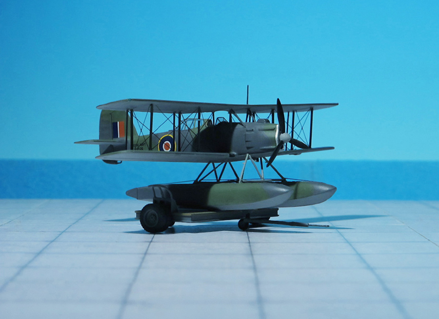
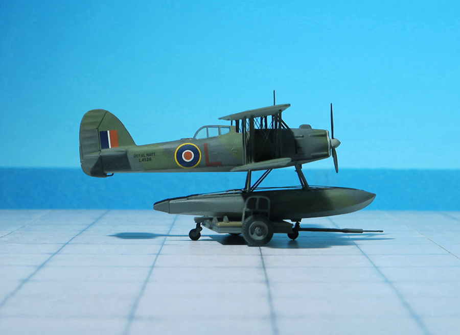
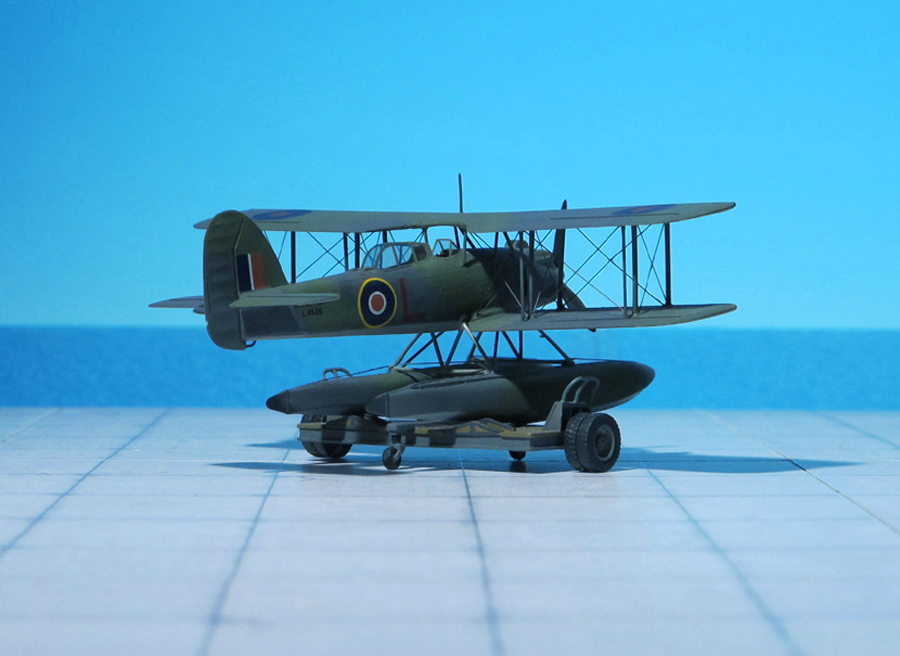
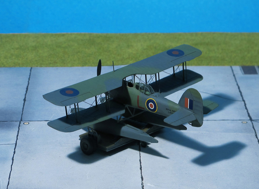
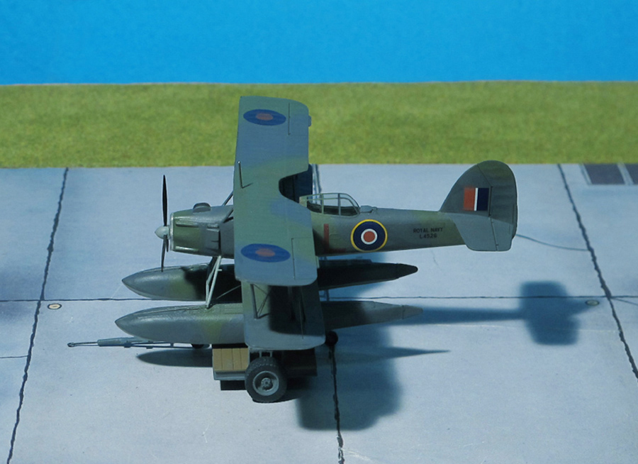
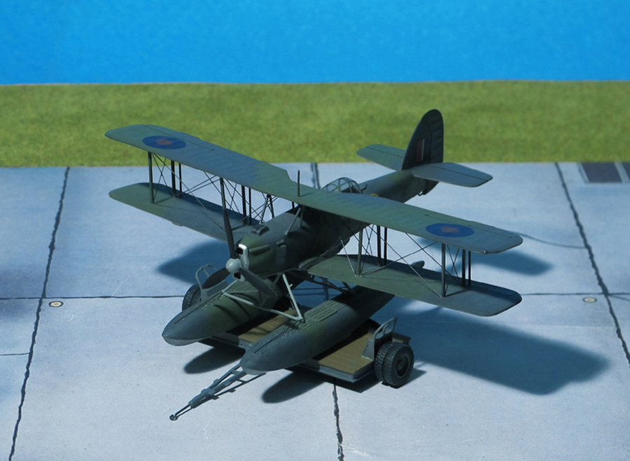
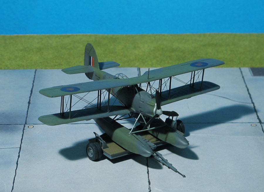
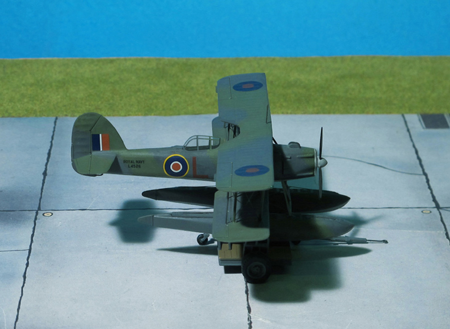
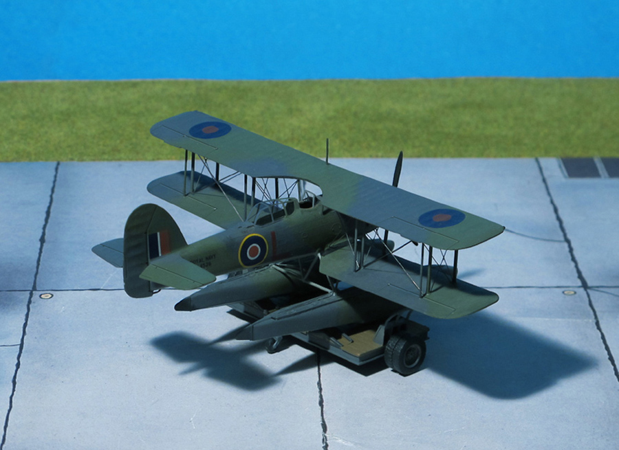
COMMENT: The Fairey Seafox was a 1930s British reconnaissance floatplane designed and built by Fairey for the Royal Fleet Air Arm. It was designed to be catapulted from the deck of a light cruiser and served in the WW II. Of the 66 built, two were finished as landplanes.
The Fairey Seafox was built to satisfy Air Ministry Specifications S.11/32. The first of two prototypes appeared in 1936, first flying on May 1936, and the first of the 64 production aircraft were delivered in 1937. The flights were organized as 700 Naval Air Squadron of the Fleet Air Arm.
The fuselage was of all-metal monocoque construction, the wings being covered with metal on the leading edge, otherwise fabric. It was powered by a 16-cylinder 395 hp air-cooled Napier Rapier H engine. It cruised at 106 mph, and had a range of 440 mi.
Although the Seafox handled well, it was criticized for being underpowered, engine cooling was poor and landing speeds were higher than desired.
In 1939, a Seafox played a part in the Battle of River Plate against the German pocket battleship “Admiral Graf Spee”, by spotting for the naval gunners. This ended with “Graf Spee’s” scuttling and destruction.
Seafoxes operated during the early part of the war from the cruisers HMS “Emerald”. “Neptune”, “Orion”, “Ajax”, “Arethusa” and “Penelope” and the armed merchant cruisers HMS “Pretoria Castle”, “Asturias” and “Alcantara”. The floatplanes remained in service until 1943 (Ref.: 24).
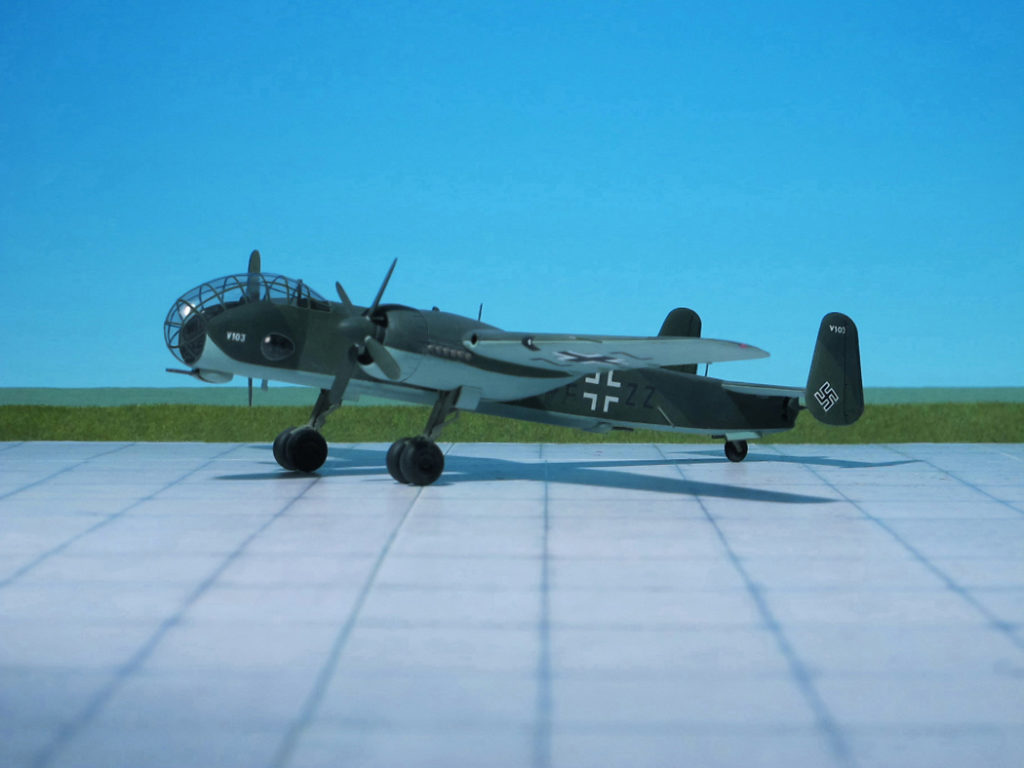
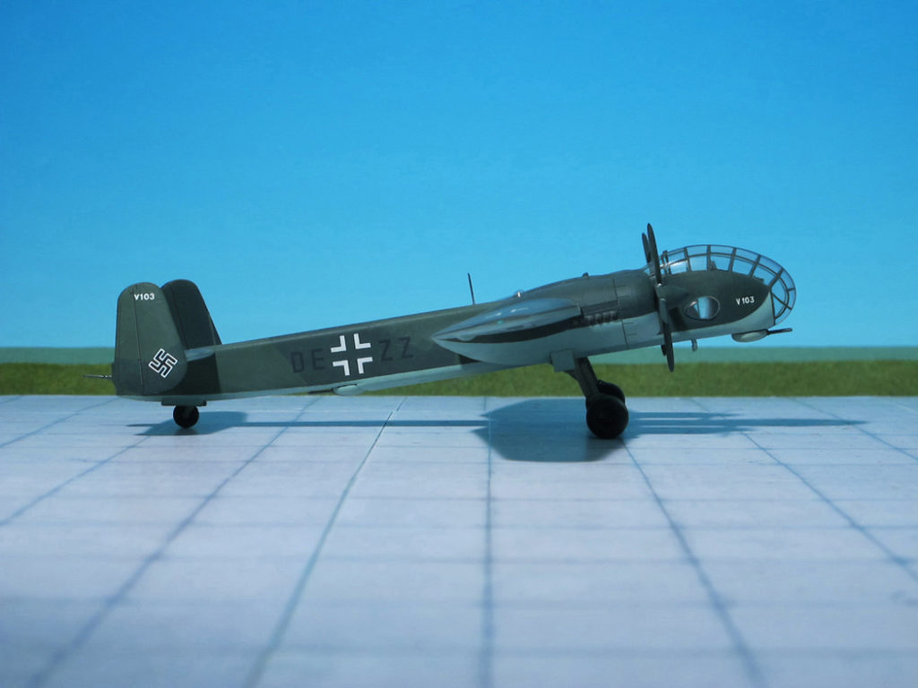
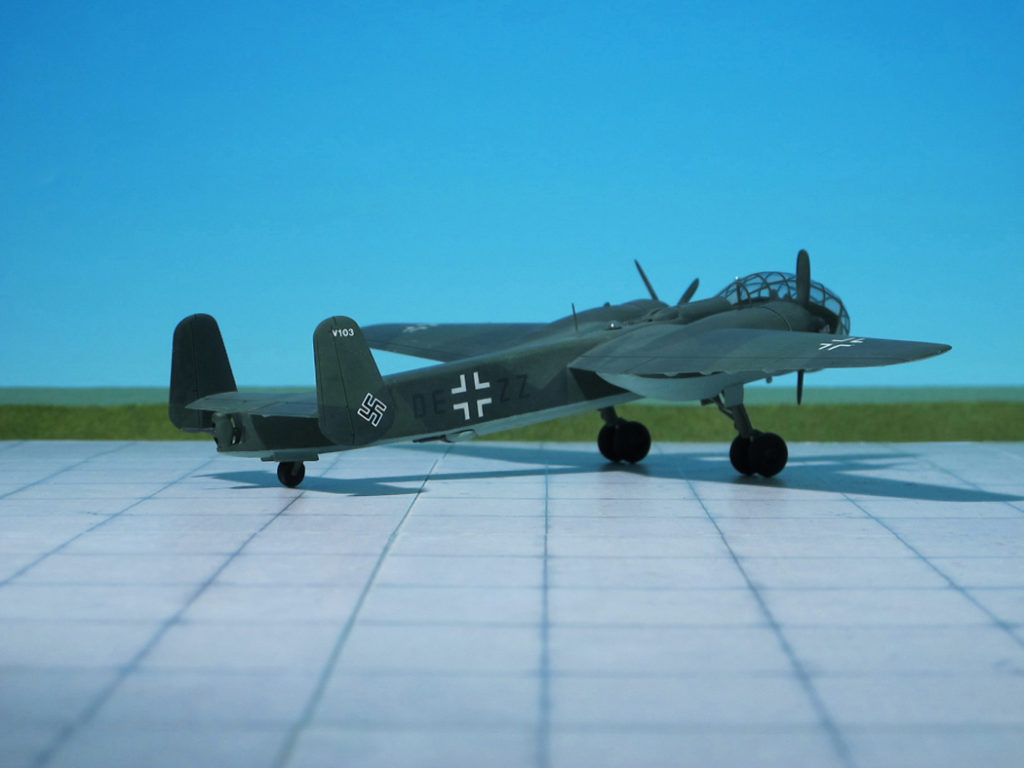
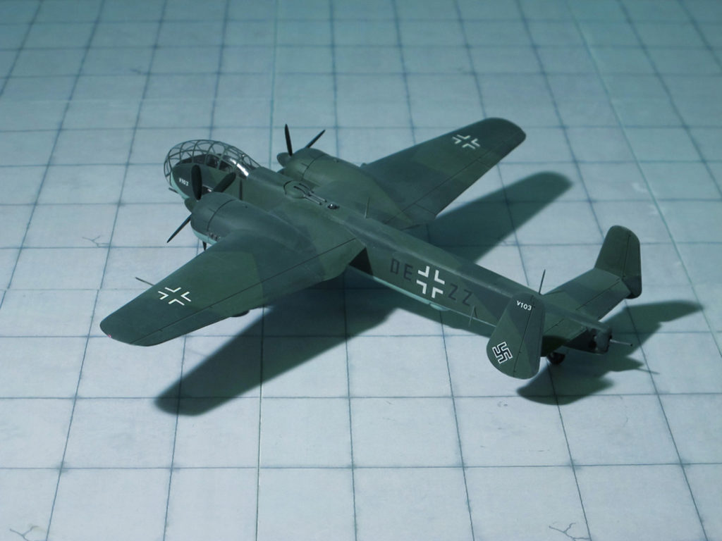
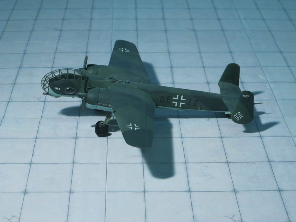
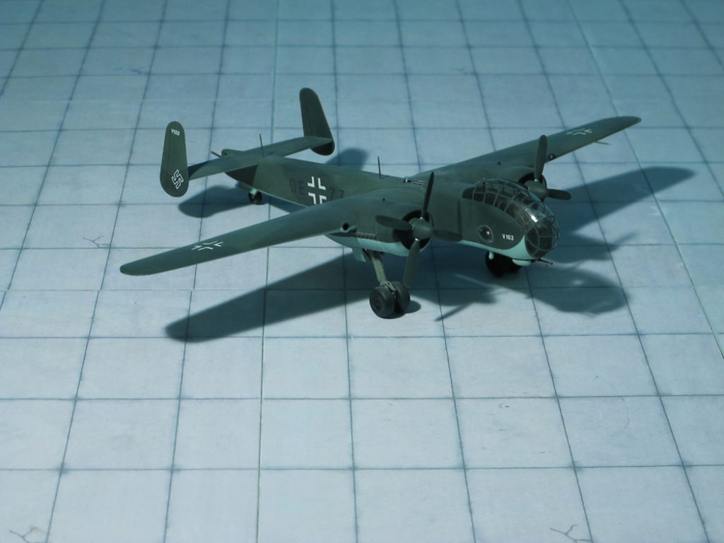
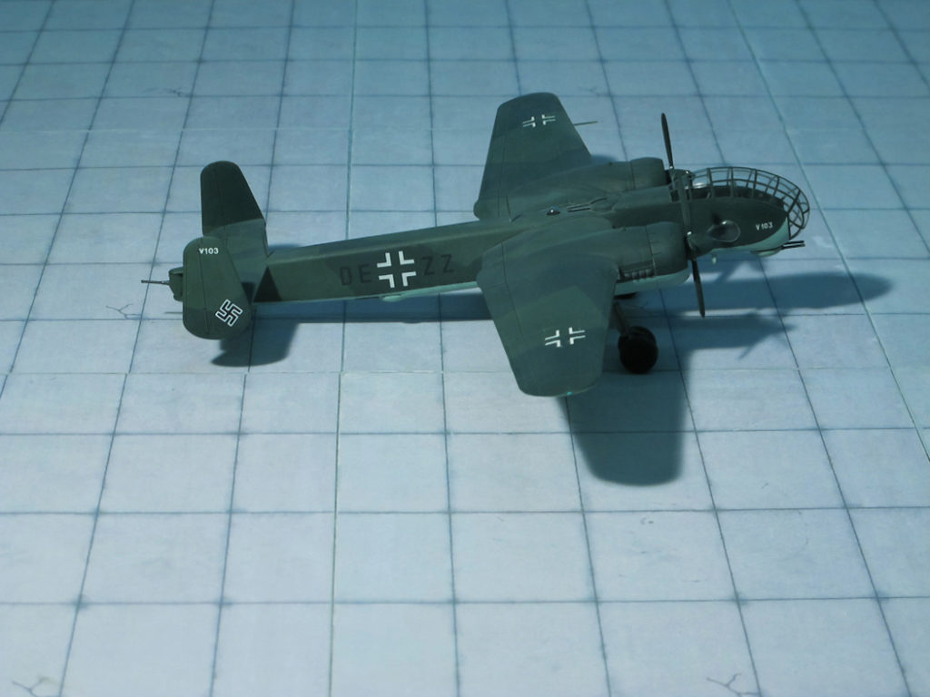
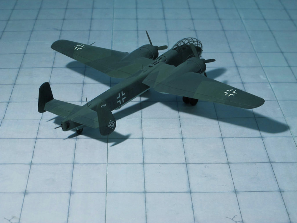
POWER PLANT: Two Daimler-Benz DB 610A-1/B-1 liquid-cooled engines, rated at 2,950 hp each
PERFORMANCE: 407 mph at 22,300 ft
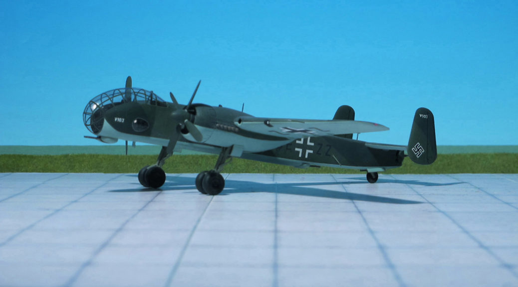
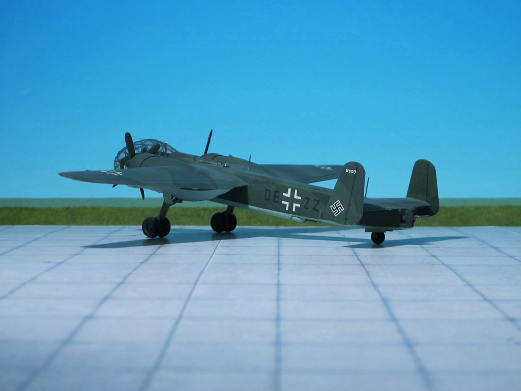
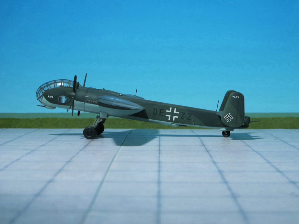
COMMENT: Prior to the receipt of RLM instructions to prepare for production of the Daimler-Benz DB 606-powered Junkers Ju 288, the Junkers construction bureau had introduced some major changes in the basic design of the bomber which had resulted in the Ju 288C intended specifically for the Daimler-Benz engines. One of the most noticeable external changes was the provision of a redesigned and elongated nose which increased overall length substantially. Defensive armament was supplemented by a ventral barbette aft of the bomb-bay, instrumentation was greatly improved and the structure was strengthened.
The first C-series prototype, the Ju 288 V101 with DB 606A/B engines, was completed in August 1942, this being followed within a few weeks by the similar Ju 288 V102.
The Ju 288C programme continued with high priority, production standards were finalized, and modifications dictated by flight test programme, together with production features, were embodied by the next prototype, the Ju 288C V103. Fitted with the more powerful DB 610 engines and introducing provision for underwing weapons racks, the Ju 288C V103 had the full complement of four remotely-controlled gun barbettes, and was flown for the first time in spring of 1943.
The Junkers Ju 288C V103 was intended as the first production prototype for the Ju 288C-1, and was rapidly followed by the Ju 288 V104 and V105 which were flown in May 1943, and the V106 which flew in June, these all being powered by DB 610A/B engines and differing only in minor items of equipment. At this time, it was proposed to manufacture the bomber in three versions which differed primarily in the defensive armament fitted. The Ju 288C-1 was to have a chin, dorsal and ventral barbettes each mounting twin MG 131 machine guns, and a tail barbette mounting a MG 151 cannon; the Ju 288C-2 was to have had twin MG 151 cannon in each chin, dorsal and ventral barbettes, and either two MG 131s in tail barbette or four MG 131 in a manned tail turret, and the Ju 288C-3 was to have been a night bomber with defensive armament restricted to twin MG 131s in a ventral barbette.
Suddenly, in June 1943, Junkers was informed by the Technische Amt that the entire “Bomber B” programme had been abandoned owing to increasing shortages of strategic materials and the effect that the launching of a major production program for a new bomber would have on existing production programmes at a critical phase in the conflict. However, despite the cancellation of the programme, Junkers completed two additional machines, the Ju 288 V107 and V 108, which were flown in July 1943, other airframes on the assembly line being scrapped. Some flight testing of the Ju 288 was continued until the summer of 1944, by which time a least 17 of the 22 prototypes had crashed while engaged in flight development. With the termination of the test programme, several of the surviving Ju 288B- and C-series prototypes were transferred to the Luftwaffe, and fitted with ventral gun pods similar to that fitted to the Junkers Ju 88P-4 and mounting a single 50 mm BK 5 (KwK 39) cannon, these saw limited operational use during the closing stages of the conflict (Ref.:7).
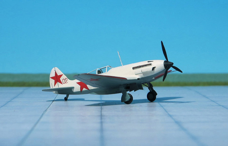
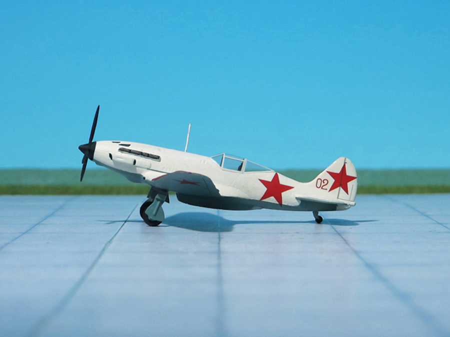
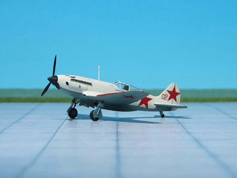
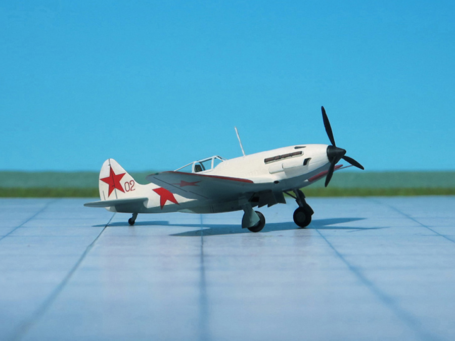
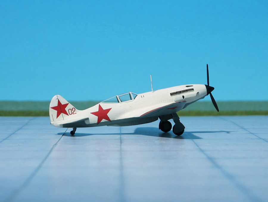
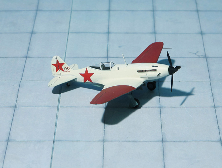
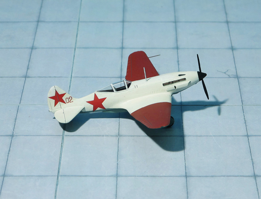
POWER PLANT: One Mikulin AM-35A liquid-cooled engine, rated at 1,332 hp
PERFORMANCE: 314 mph at 25,590 ft
COMMENT: The Mikoyan-Gurevich MiG-3 was a Soviet fighter and interceptor aircraft used during World War II. It was a development of the Mikoyan-Gurevich MiG-1 by the Experimental Design Department of Factory No. 1 to remedy problems found during the MiG-1’s development and operations. It replaced the MiG-1 on the production line at Factory No. 1 on December 1940 and was built in large numbers during 1941 before Factory No. 1 was converted to build the Ilyushin Il-2.
The large number of defects noted during flight testing of the MiG-1 forced Mikoyan and Gurevich to make a number of modifications to the design. Testing was done on a full-size aircraft in the T-1 wind tunnel belonging to the Central Aero and Hydrodynamics Institute (TsAGI) to evaluate the problems and their proposed solutions. The first aircraft to see all of these changes applied was the fourth prototype of the I-200. It first flew on 29 October 1940 and was approved for production after passing its State acceptance trials. The first MiG-3, as the improved aircraft was named on December 1940, was completed same month and another 20 were delivered by the end of the year.
Changes included: the engine was moved forward, outer wing panel dihedral was increased by one degree to increase lateral stability, the back of the pilot’s seat was armored with an 8 mm plate (increased to 9 mm in later models, the supercharger intakes were streamlined, the main landing gear was strengthened and the size of the main wheels was increased and the canopy glazing was extended aft to improve the view to the rear which allowed for the installation of a shelf behind the pilot for an RSI-1 radio (later upgraded to an RSI-4)
Despite the teething problems with the MiG-3, a number of reports had been received about poor quality aircraft received by the regiments which pointed directly at the NII VVS (Naoochno-Issledovatel’skiy Institoot Voyenno-Vozdooshnykh Seel—Air Force Scientific Test Institute) as it was responsible for monitoring the quality of the aircraft delivered to the VVS (Soviet Air Force). After elimination of most problems the production started and 3,422 aircraft were built in different factories spread over the eastern parts of Soviet Union.
The MiG-3’s top speed of 398 mph at 23,622 ft was faster than the 382 mph of the German Messerschmitt Bf 109F-2 in service at the beginning of 1941 and the British Supermarine Spitfire Mk. V’s 375 mph. At lower altitudes the MiG-3’s speed advantage disappeared as its maximum speed at sea level was only 314 mph while the Bf 109F-2 could do 320 mph. Unfortunately for the MiG-3 and its pilots, aerial combat over the Eastern front generally took place at low and medium altitudes where it had no speed advantage.
MiG-3s were delivered to frontline fighter regiments beginning in the spring of 1941 and were a handful for pilots accustomed to the lower-performance and docile Polikarpov I-152 and I-153 biplanes and the Polikarpov I-16 monoplane. It remained tricky and demanding to fly even after the extensive improvements made over the MiG-1 Many fighter regiments had not kept pace in training pilots to handle the MiG and the rapid pace of deliveries resulted in many units having more MiGs than trained pilots during the German invasion. By June 1941, 1,029 MIG-3s were on strength, but there were only 494 trained pilots. However high-altitude combat of this sort was to prove to be uncommon on the Eastern Front where most air-to-air engagements were at altitudes well below 16,000 ft. At these altitudes the MiG-3 was outclassed by the Bf 109 in all respects, and even by other new Soviet fighters such as the Yakovlev Yak-1. Furthermore, the shortage of ground-attack aircraft in 1941 forced it into that role as well, for which it was totally unsuited.
Over the winter of 1941–42 the Soviets transferred all of the remaining MiG-3s to the Soviet Naval Aviation and Soviet Air Defence Forces (PVO) so that on 1 May 1942 none were left on strength with the VVS. By May 1942, Naval Aviation had 37 MiGs on strength, while the PVO had 323 on hand on May. By June 1944, the Navy had transferred all its aircraft to the PVO, which reported only 17 on its own strength, and all of those were gone by January 1945. Undoubtedly more remained in training units and the like, but none were assigned to combat units by then (Ref.: 24).
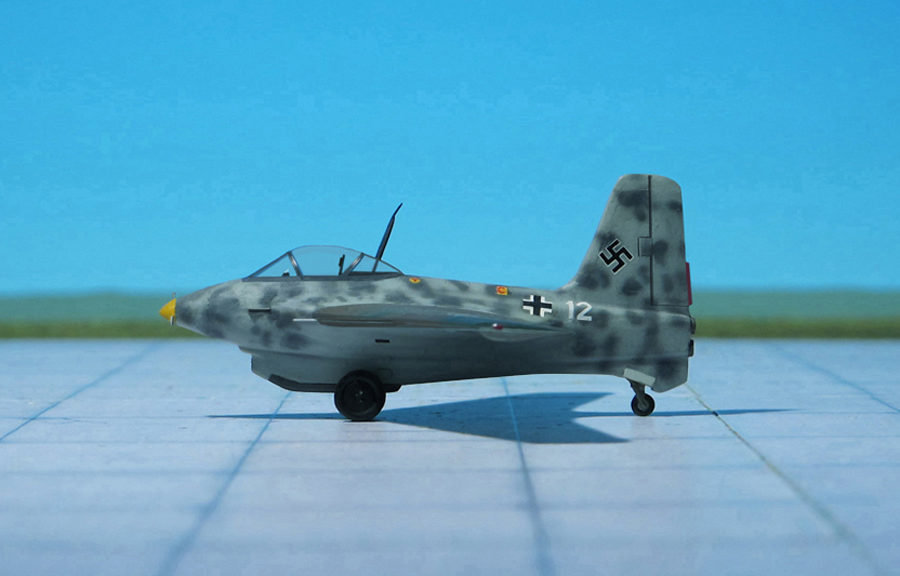
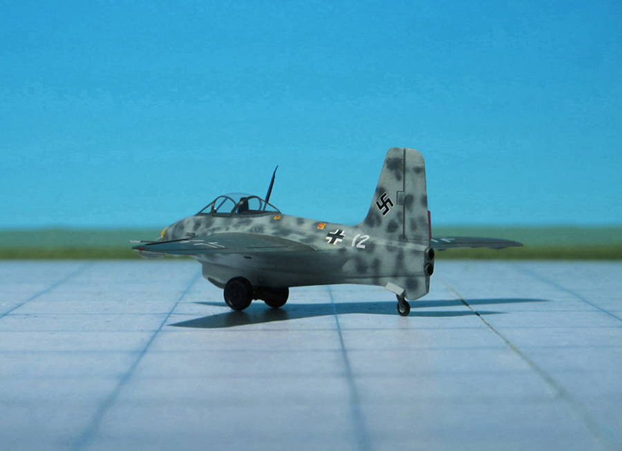
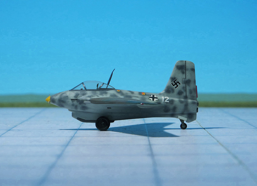
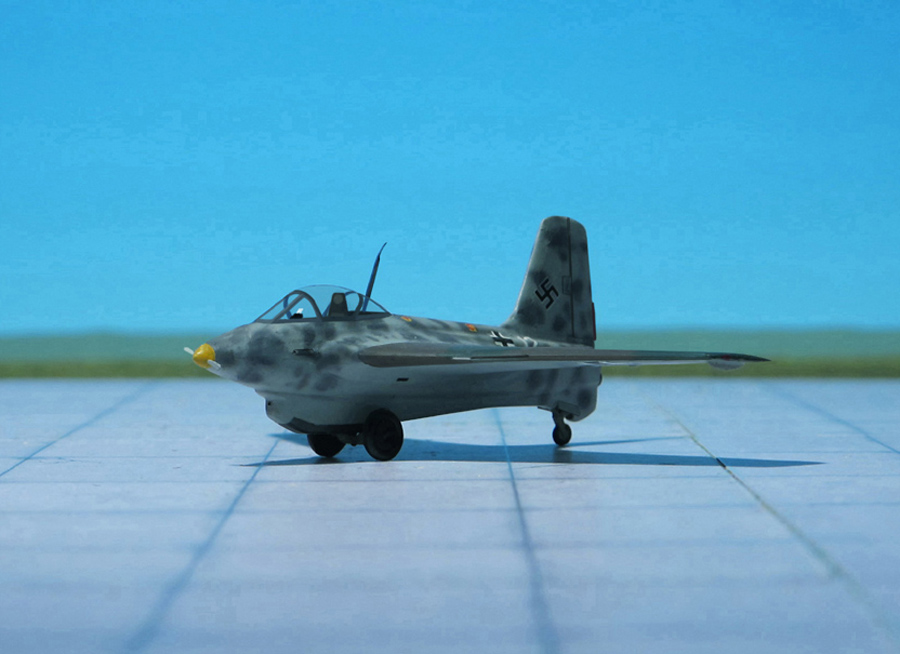
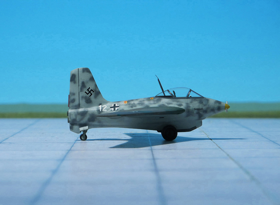
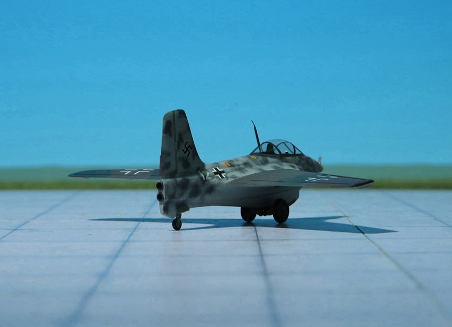
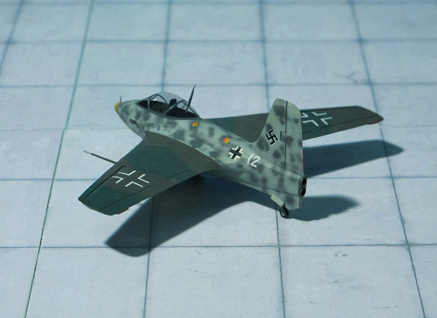
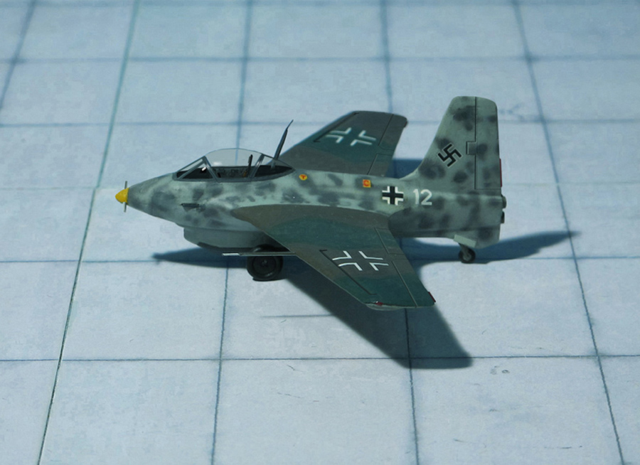
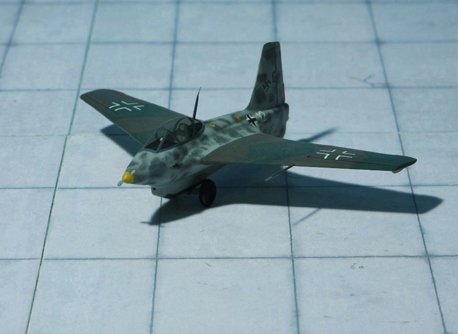
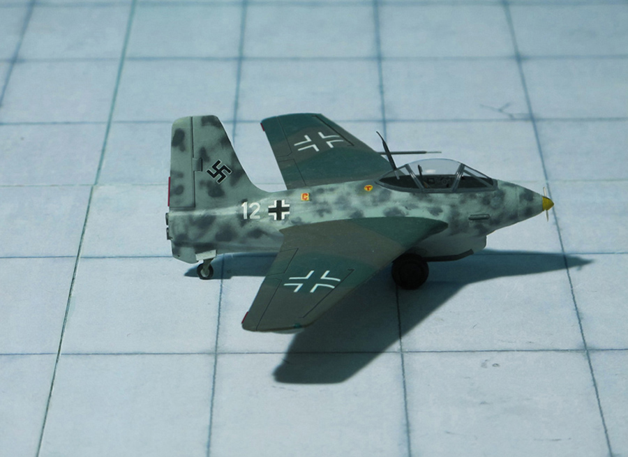
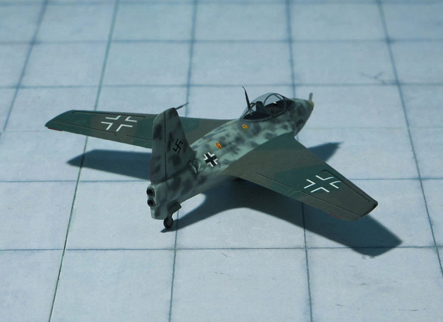
POWER PLANT: One Walter HWK 509C-1 bi-fuel rocket engine, rated at 2,000 kp main chamber plus 400 kp auxiliary chamber
PERFORMANCE: 596 mph at 40,000 ft.
COMMENT: As soon as it was realized that the HWK 509A rocket engine of the Messerschmitt Me 163B “Komet” consume appreciable more fuel than had been calculated, reducing commensurately the powered endurance of the aircraft, Professor Walter began investigating the possibility of introducing an auxiliary cruising chamber which achieved test status during 1944 in two B-series prototypes, the Me 163B V6 and Me 163B V18, these subsequently serving as test beds for the Me 163C-series. The cruising chamber afforded a thrust of 400 kp which was additional to the normal full-power thrust rating, and the intention was that the aircraft should take off and climb to operational altitude with both rocket chambers operating at full thrust, then cut the main chamber and cruise on the power of the auxiliary chamber alone. Apart from provision of a fully-retractable tailwheel which was positioned further forward to allow for the twin vertically-disposed rocket pipes, some revision of the keel line and shortening of the landing skid, the Me 163B V6 and Me 163B V18 were externally similar to the standard Me 162B-series production aircraft.
On July 1944, test pilot Rolf Opitz took off from Peenemünde in the Me 163B V18 for the first climb calibration trials with both rocket chambers functioning. Everything went according to plan until, just above 13,000 ft., the aircraft began to accelerate. At 14,760 ft. the climb rate of the aircraft was still increasing and within four seconds the aircraft has passed 16,400 ft. Another few seconds and the aircraft exceeded its critical Mach number, and Opitz promptly cut the rocket motor. The prototype immediately went into a steep dive from which Opitz only succeeded in recovering a few feet above the waters of the Baltic Sea. After landing back at Peenemünde Opitz discovered that almost the entire rudder of the aircraft had been ripped away, and it was subsequently ascertained the Me 163B V18 had attained a speed of 702 mph.
While test with both prototypes were proceeding, the Messerschmitt drawing office was working on a refined version of the rocket fighter, the Messerschmitt Me 163C, intended from the onset to utilize the auxiliary cruising chamber. While the wings of the new model were essentially similar to those of the Me 163B, a new centre section was introduced which increased overall span and gross area. This was married to an enlarged fuselage of improved fineness ratio which accommodated the pilot in a pressurized cockpit enclosed by a blister-type all-round vision canopy. The T-Stoff and C-Stoff tankage was increased and the armament, which could comprise either two 20-mm MG 151 or two 30-mm MK 108 cannon, was transferred from the wing roots to the fuselage. The additional tank capacity and cockpit pressurization allowed the maximum altitude to increase to 52,000 ft, as well as improving powered time to about 12 minutes, almost doubling combat time (from about five minutes to nine).
Preparations for the series production of the new model as Messerschmitt Me 163C-1a began late in 1944, but only three were reportedly completed, the being allocated “Versuchs” number as Me 163C V1, V2 And V3, and only one is known to have flown before all three were destroyed to prevent them falling into Soviet hands (Ref.: 7).
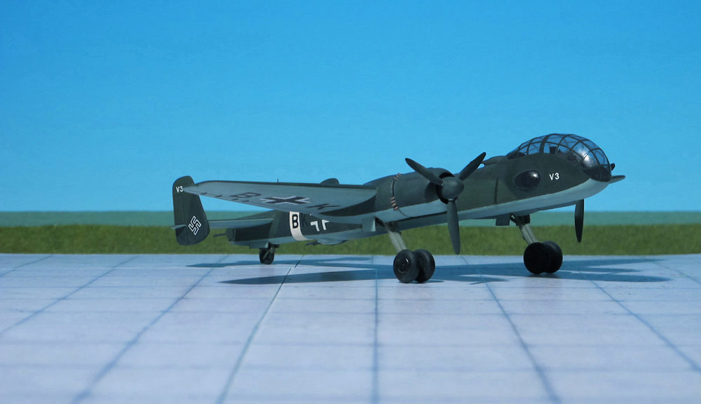
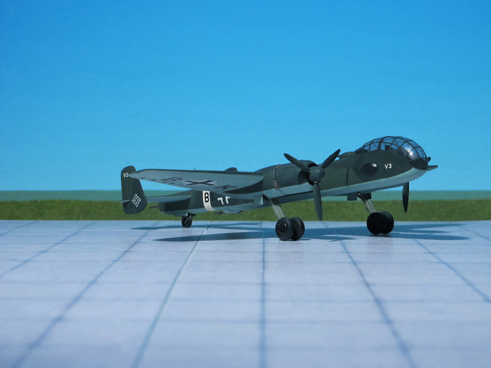
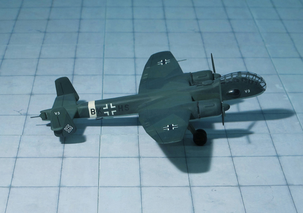
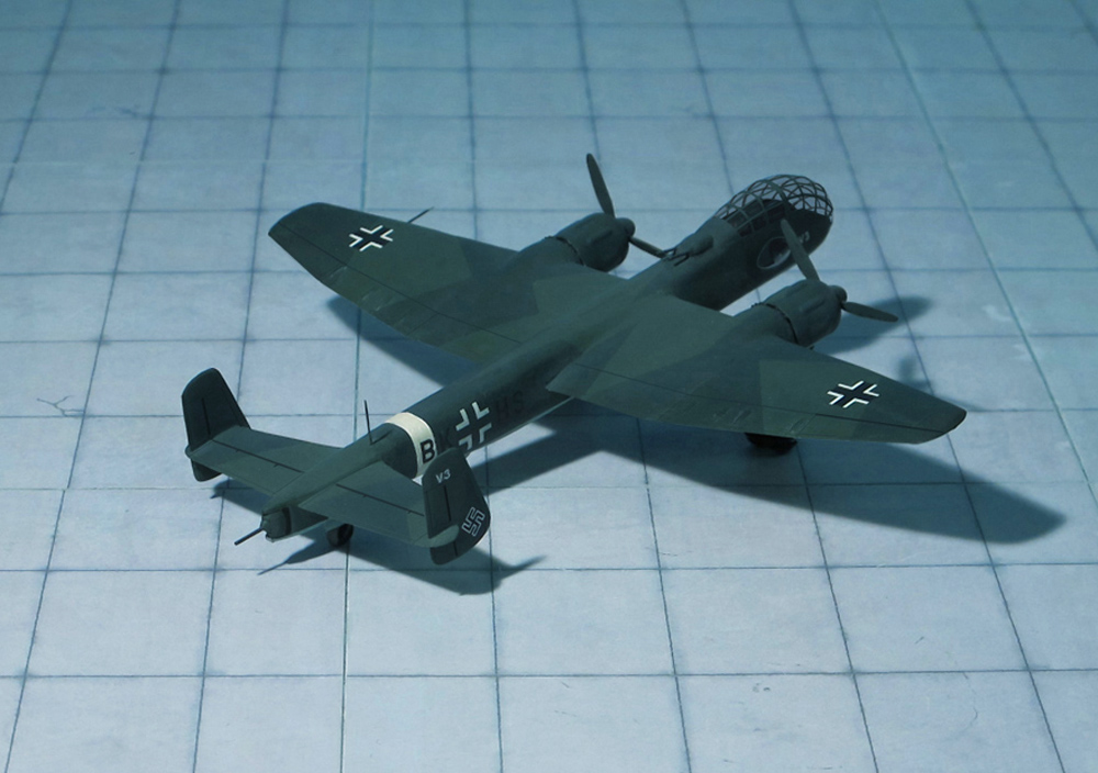
POWER PLANT: Two BMW 801MA radial engines, rated at 1,677 hp each
PERFORMANCE: 388 mph
COMMENT: The Junkers Ju 288, originally known within the Junkers Company as the EF 074, was a German bomber project designed during WW II, which only ever flew in prototype form. The first of an eventual 22 development aircraft flew on 29 November 1940.
The Ju 288 was the winner of the “Bomber B” contest, although the contest was started by Junker’s submission of the EF 074 and their selection was never really in doubt. “Bomber B” intended to replace the Junkers Ju 88 with a design that was larger, offer cabin pressurization for high altitude work, have longer range, a much greater war load, be even faster, and have improved defensive firepower. The design would replace all the bombers then in German Luftwaffe service.
Delivering all of these requirements in a single airframe demanded much more powerful engines, and all of the “Bomber B” concepts relied on the Junkers Jumo 222 engine to deliver this power. Ultimately, the Jumo 222 was a failure in spite of massive effort and several redesigns over a period of several years. No suitable replacement was ever forthcoming, dooming the Ju 288 program, and leaving the Luftwaffe with older bomber designs during the second half of World War II.
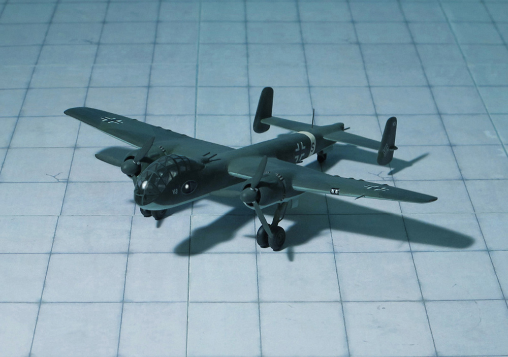
Junkers had been outlining a variety of improved models of the Ju 88 since 1937, powered by the planned Jumo 222 multibank engine, or Jumo 223 inline multibank diesel of greatly increased power of at 2,000 horsepower. The EF 074 was essentially a scaled-up Ju 88, sharing its general layout and most of its fuselage and wings with extensions in various places. The nose was redesigned with a more streamlined “stepless” cockpit, having no separate windscreen panels for the pilot and co-pilot. This layout allowed cabin pressurization to be more easily implemented. This design approach had been growing in favour, subsequently appearing in various German types, notably the Heinkel He 111P and H’s.
No serious work was undertaken on these versions, but after Heinrich Hertel left Heinkel and joined Junkers in 1939, the EF 074 design was submitted to the RLM in May 1939. Accordingly, the RLM sent out the specifications for the “Bomber B” design competition in July, the Ju 88 retroactively becoming the second aircraft to be designated “Bomber A”, as the June 1936 specification for the Heinkel He 177 also had that name. The “Bomber B” program aimed at replacing all of the medium bombers in the Luftwaffe inventory with a new design based on the EF.74 or something with equal performance. “Bomber B” was intended to have even better speed than the Ju 88, high-altitude cruising with a pressurized cockpit, heavier defensive armament, range allowing it to cover any point in the British Isles, and a 4,000 kg war load, double that of the earlier generation bombers. A number of companies returned proposals, but these were to some extent a formality, the EF.74 had already been selected as the winner, and of the rest of the designs submitted, only the Focke-Wulf Fw 191 and Dornier Do 317 progressed even as far as prototypes, and the Henschel Hs 130 coming under consideration as a late entrant.
Work began on building prototypes in early 1940, and the first example was completed by mid 1940. Power was supposed to be supplied by two Junkers Jumo 222 six-bank, four cylinders per bank, over 2.000 hp output class powerplants, but problems with the Jumo 222’s development — as with almost every new concept for over 2.000 hp output reciprocating aircrafts engienes then underway in the Third Reich — meant the first prototypes flew with BMW 801 radial engines, instead. The first flight-quality Jumo 222s did not arrive until October 1941, and even at this point it was clear they were nowhere near ready for full-scale production. When it became apparent the Jumo 222 was not likely to become a viable powerplant, in May 1942, Junkers proposed replacing them, for their projected Ju 288C version, with the much heavier Daimler Benz DB 606‘s instead; the same 1.5 tonne, twin-crankcase „weldet-together engines“ that Reichsmarschall Hermann Göring complained about some three months later, regarding the Heinkel He 177’s own endless powerplant troubles
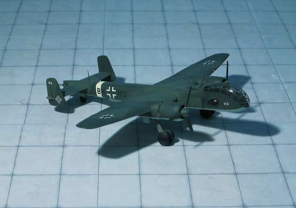
Late in January 194, after protracted ground trials, the first prototype, the Ju 288 V1, was flown for the first time. It was powered by two BMW 801 MA engines, each rated at 1,600 hp. The defensive armament arrangement reverted to that of the original EF 074 proposal, dummy barbettes being mounted in forward dorsal and aft ventral positions.
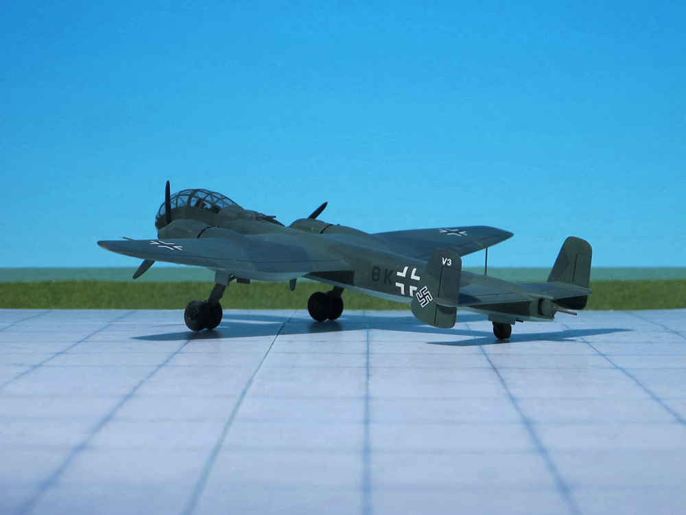
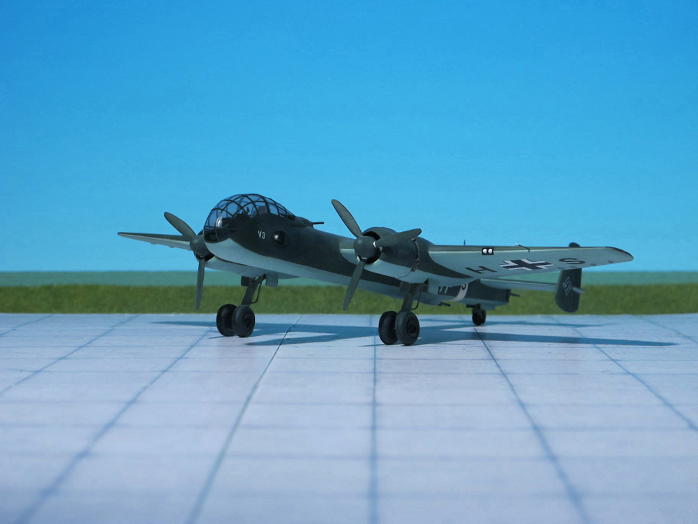
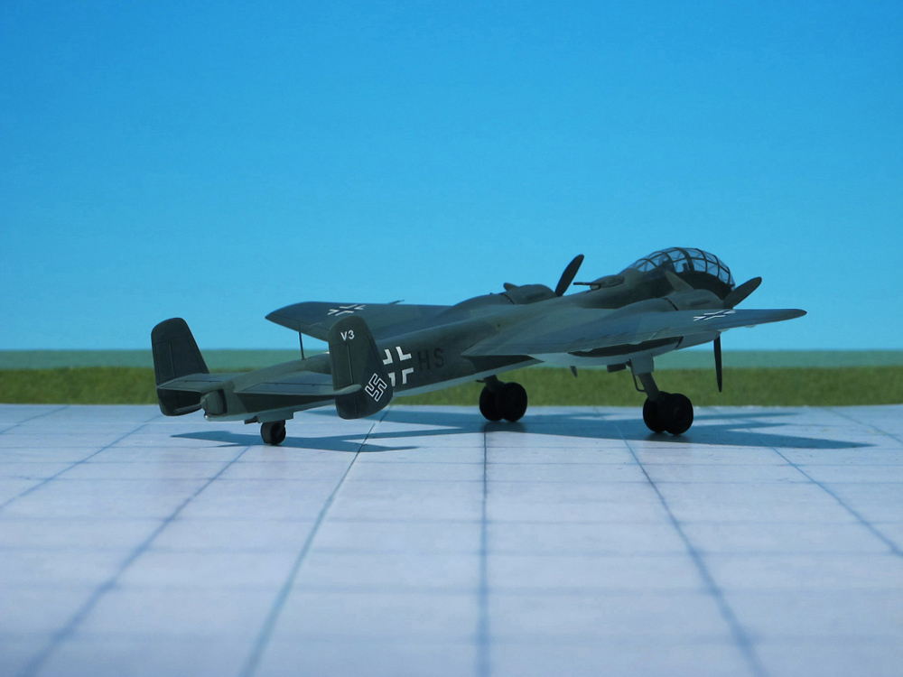
During the early spring 1941, the first prototype was joined by the Ju 288 V2 which differed from its predecessor only in having spoiler-type dive brakes in place of slatted-type surfaces which were also featured by the Ju 288 V3, this third prototype commencing flight trials during the early summer, by which time work had begun on a further series of prototypes, the first of these being the Ju 288 V4.
The Ju 288’s intricate main landing gear system’s design proved to be troublesome. Such a complex main gear design, with only the single pivoting retraction point for its oleo struts taking the primary stress of touchdown, was likely only one of the many potential sources of trouble causing the Ju 288’s main gear units to repeatedly collapse on touchdown.
Although the Junkers Ju 288 never even reached production status, let alone official operational service, the aircraft did see limited combat duty. In 1944, following the cancellation of the Ju 288 programme, the surviving A and C series prototypes were hurriedly fitted with defensive armament and equipment and deployed as reconnaissance bombers on the Western Front. Very few missions were flown, owing to the scarcity of aviation fuel and spare parts, and the unresolved problems with the aircraft’s power plant and undercarriage. It is believed] that the few Ju 288’s were attached to the same unit operating the small number of Junkers Ju 388 reconnaissance planes that saw service (Ref.: 7. 24).
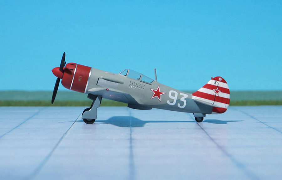
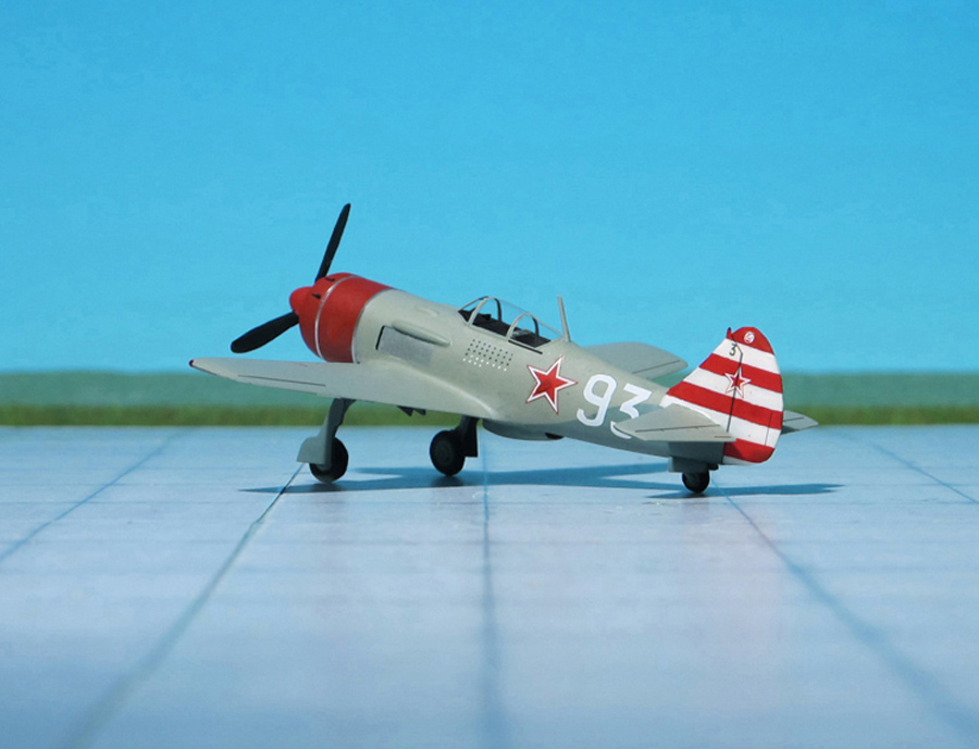
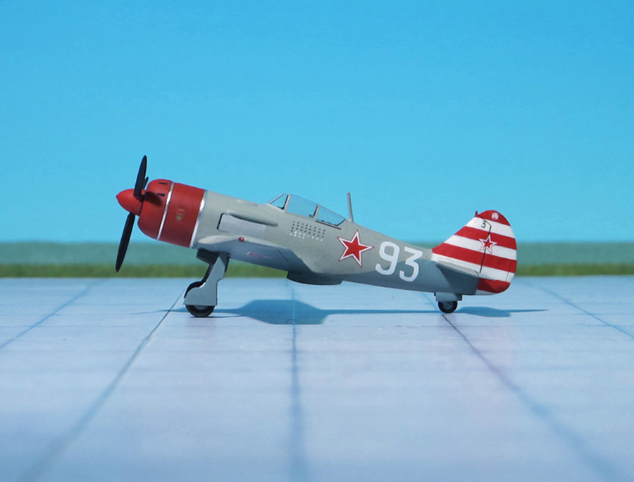
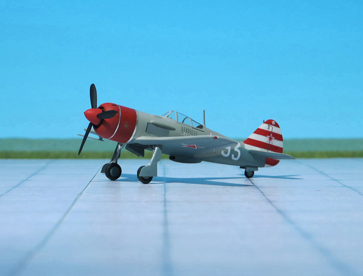
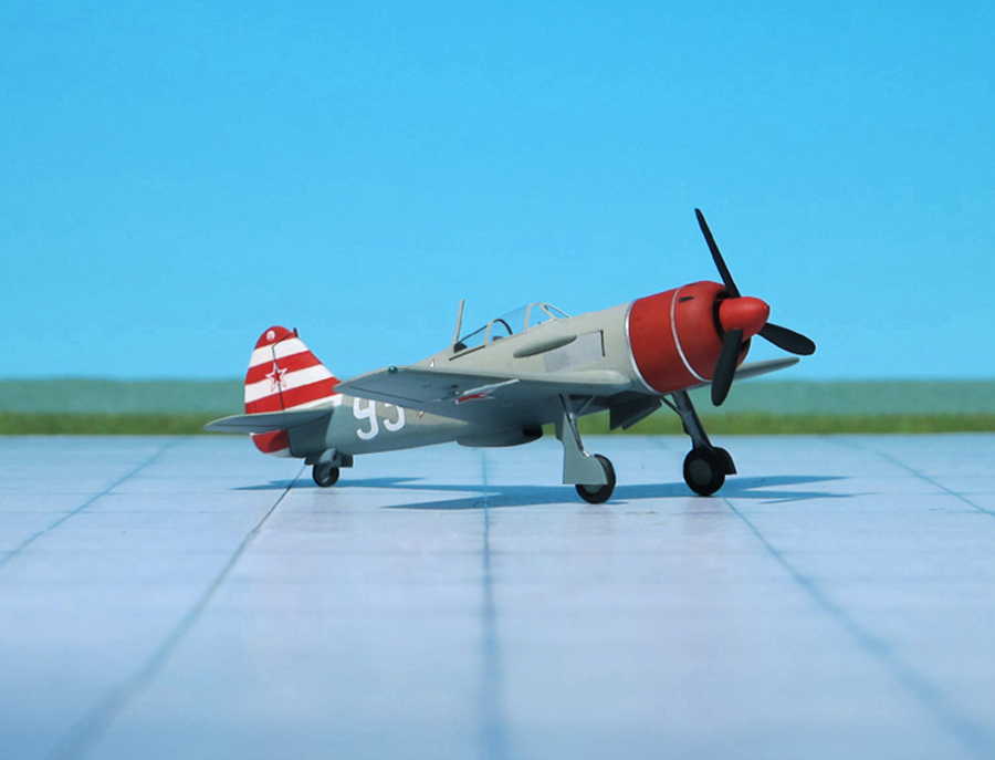
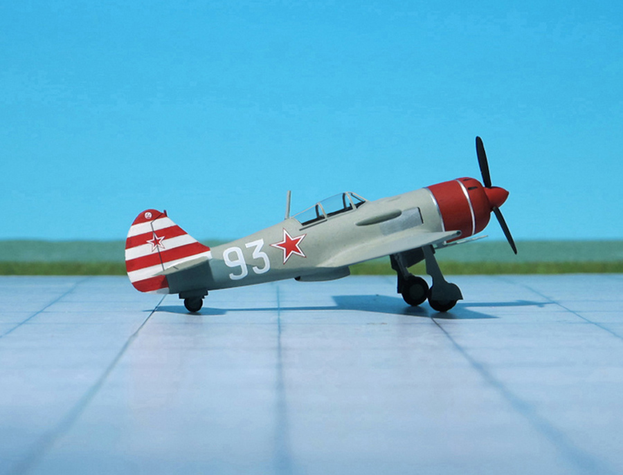
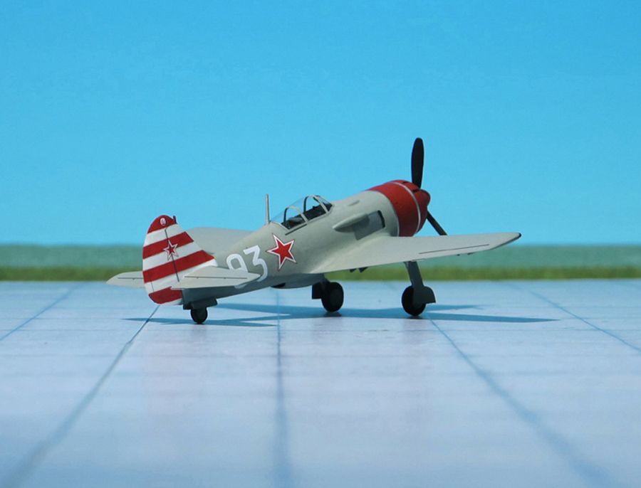
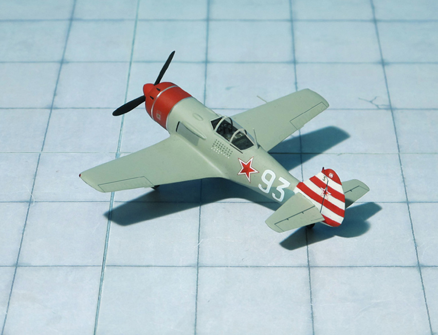
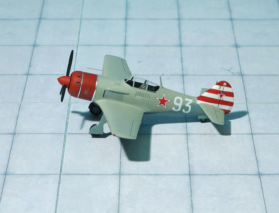
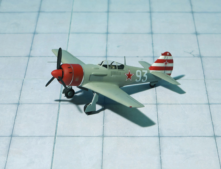
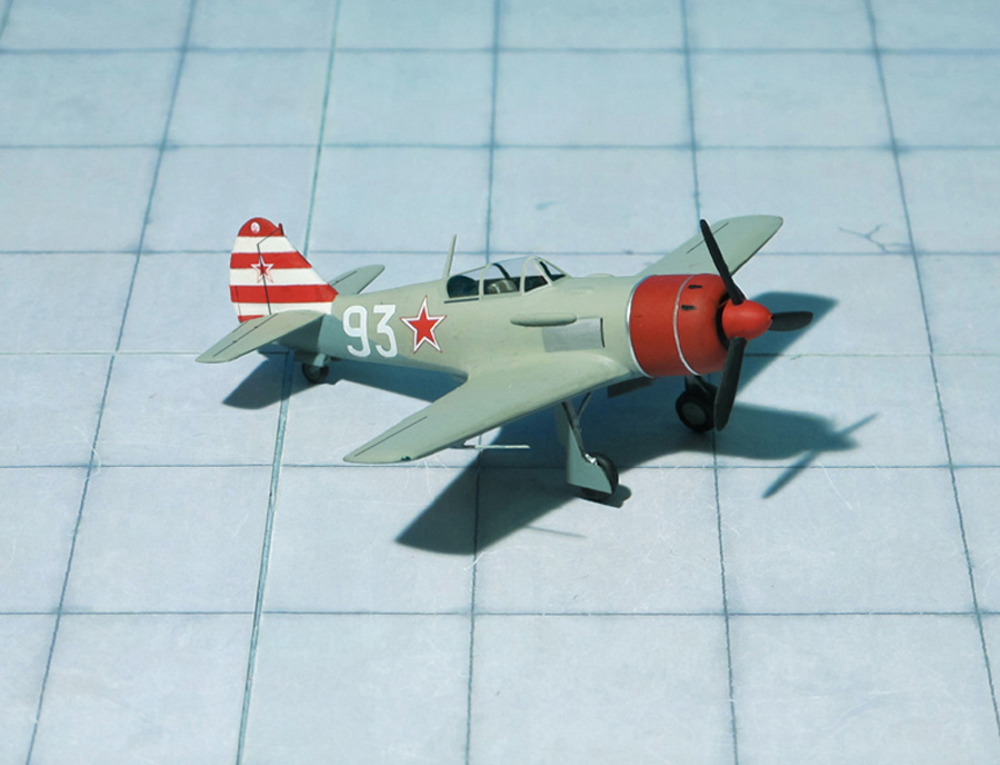
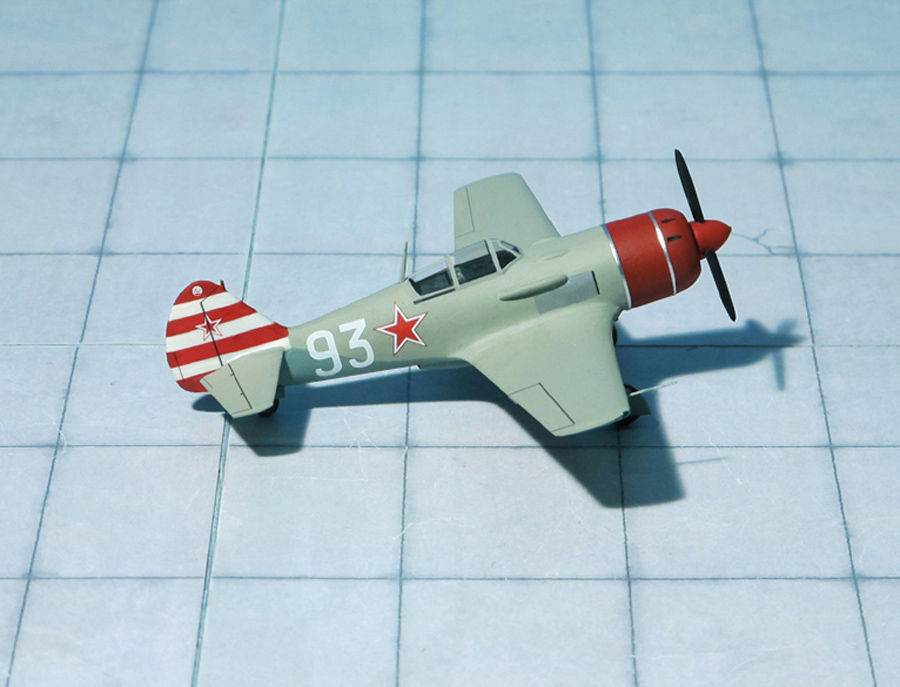
POWER PLANT: One Shvetsov Ash-82FN radial engine with a two-stage supercharger and fuel injection, rated at 1,850 hp
PERFORMANCE: 428 mph
COMMENT: The Lavochkin La-9 was a Soviet fighter aircraft produced shortly after World War II. It was a piston engined aircraft produced at the start of the turbojet age.
The Lavochkin La-9 represents a further development of the Lavochlin La-126 prototype. The first prototype, designated La-130 was finished in 1946. Similarity to the famous Lavochkin La-7 was only superficial. The new fighter had an all-metal construction and a laminar flow wing. Weight savings due to elimination of wood from the airframe allowed for greatly improved fuel capacity and four-cannon armament. Mock combat demonstrated that the La-130 was evenly matched with the La-7 but was inferior to the Yakovlev Yak-3 in horizontal flight. The new fighter, officially designated La-9, entered production in August 1946. A total of 1,559 aircraft were built by the end of production in 1948.
Like other aircraft designers at the time, Lavochkin was experimenting with using turbojet propulsion to augment performance of piston-engined fighters. One such attempt was Lavochkin La-130R with an RD-1Kh3 liquid-fuel rocket engine in addition to the Shvetsov Ash-82FN piston power plant. The project was cancelled in 1946 before the prototype could be assembled.
A more unusual approach was Lavochkin La-9RD which was tested in 1947–1948. It was a production La-9 with a reinforced airframe and armament reduced to two cannons, which carried a single RD-13 pulsejet (a German Argus As 014 engine which powered the Fieseler Fi 103, V-1 flying bomb, probably taken from surplus Luftwaffe stocks) under each wing. The 45 mph increase in top speed came at the expense of tremendous noise and vibration. The engines were unreliable and worsened the handling. The project was abandoned although between 3 and 9 La-9RD were reported to perform at airshows, no doubt pleasing the crowds with the noise.
One of the recommendations from the government testing of Lavochkin La-9 prototype was to further develop it into a long-range escort fighter, the Lavochkin La-11 (Ref.: 24).
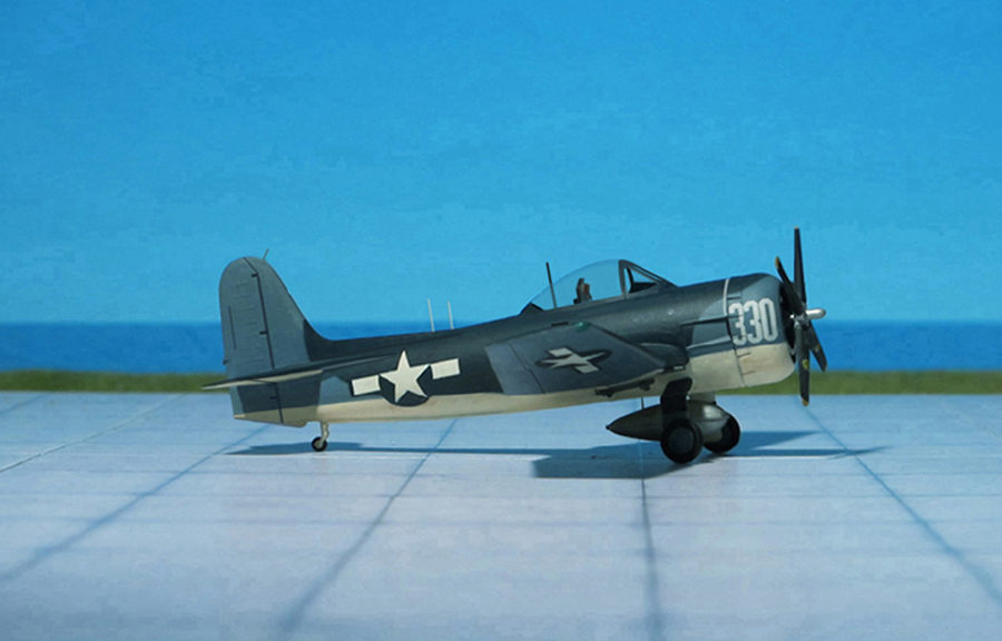
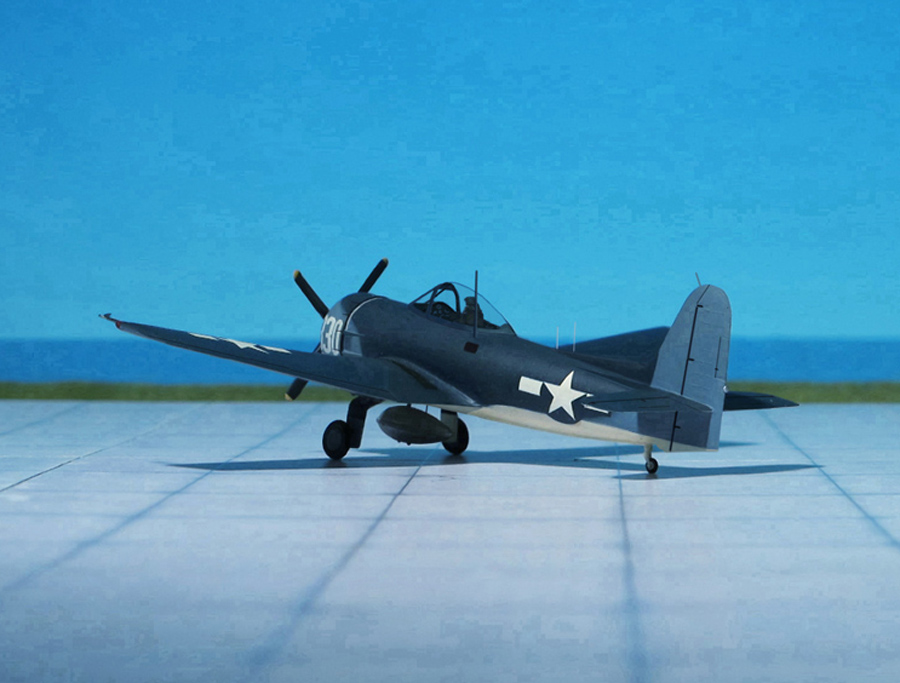
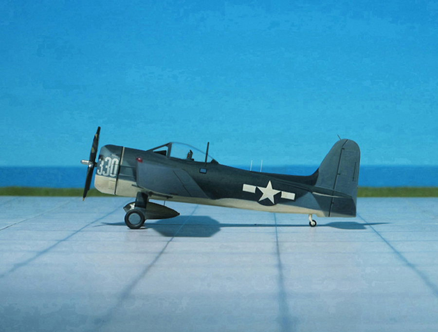
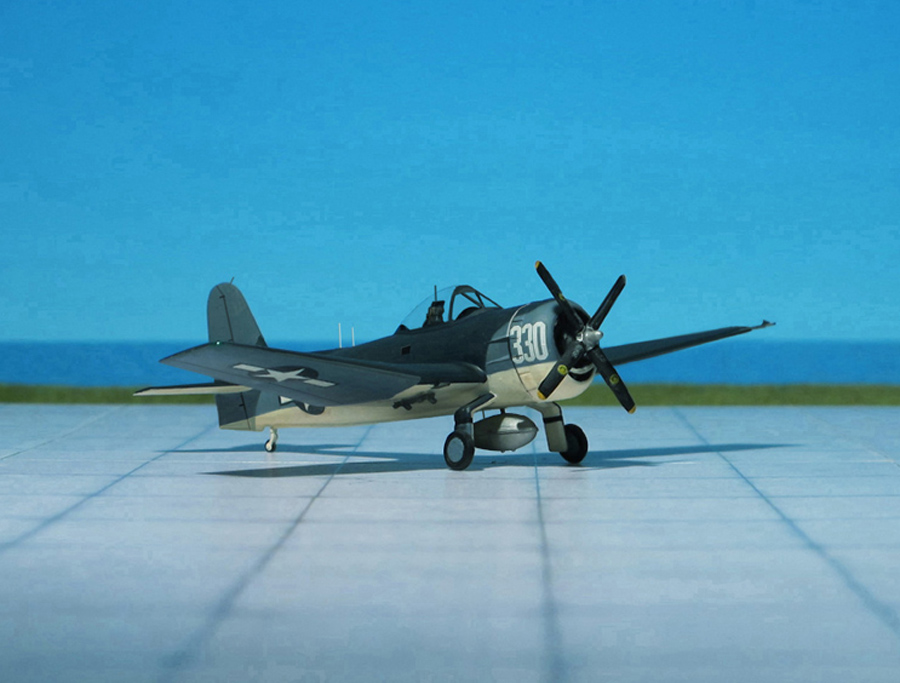
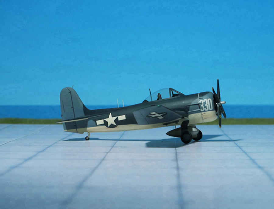
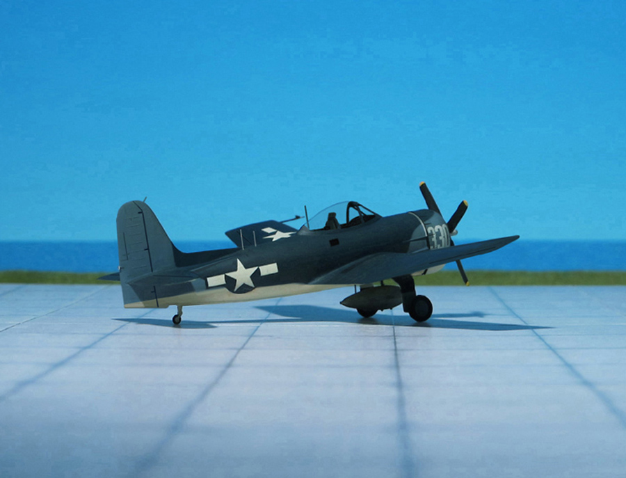
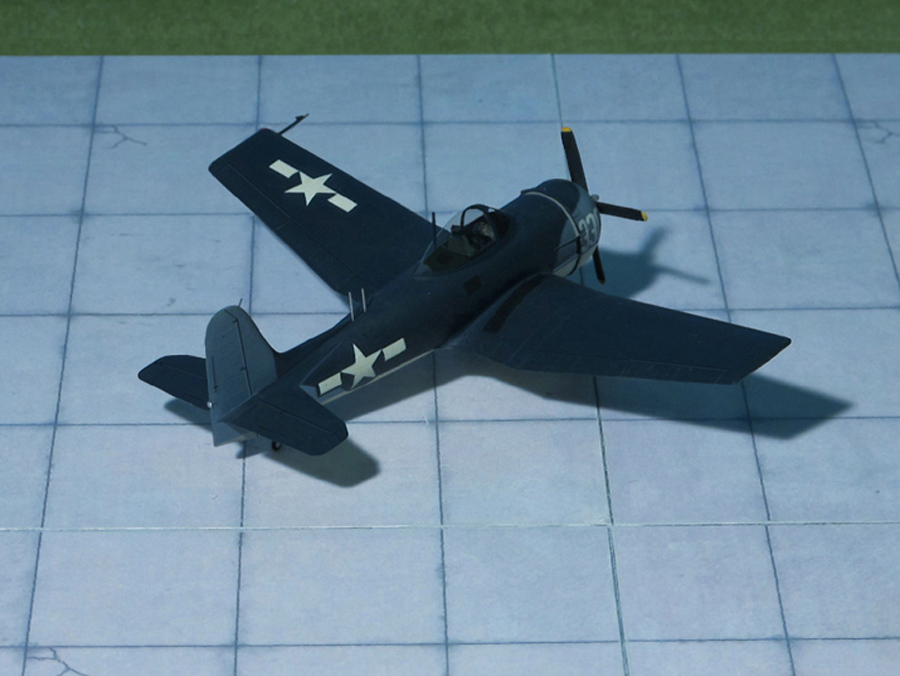
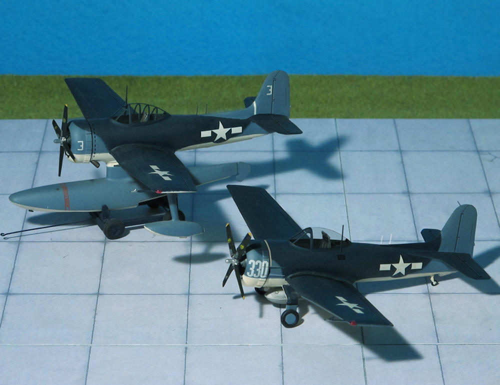
POWER PLANT: One Wright R-1820-76 “Cyclone” radial engine, rated at 1,425 hp
PERFORMANCE: 315 mph
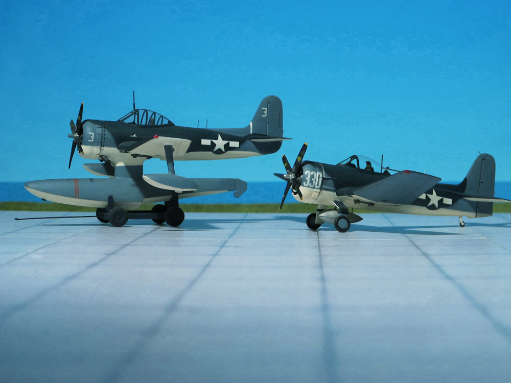
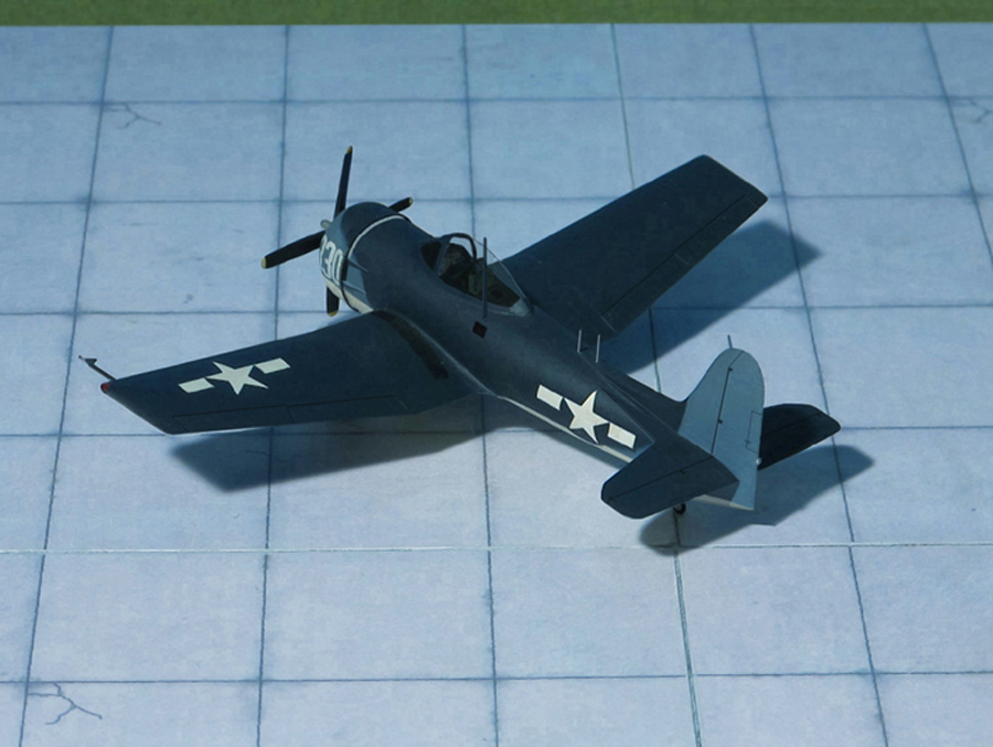
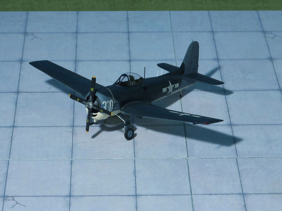
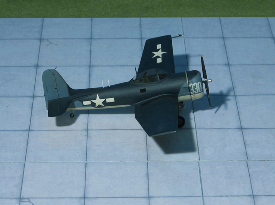
COMMENT: Last of a long line of US Navy scouting airplanes designed to serve aboard battleships as well as carriers and from land bases, the Curtis SC-1 Seahawk originated to a specification issued to industry in June 1942. The requirement was for a convertible land or floatplane with a much improved performance over the observation/scouts then in service and with provision for catapult launching.
The Curtiss design proposal in response to the specification was quickly adopted by the Navy, which issued a letter of intent on October,1942 and a contract for two prototypes on March 1943, with the designation XSC-1. A production order for 500 SC-1 followed on June 1943, and the first XSC-1 made its first flight on February 1944. Flight testing continued through April, when the last of the seven pre-production aircraft took to the air.
The first serial production “Seahawks” were delivered on October 1944, to the USS CB-2 Guam, an Alaska-class large cruiser. She carried four Seahawk floatplanes, housed in two hangars with a pair of aircraft catapults mounted amidships.
All 577 Seahawk aircraft eventually produced for the Navy were delivered on conventional landing gear and flown to the appropriate Naval Air Station, where floats were fitted for service as needed.
Nine further prototypes were later built as Curtis SC-2 Seahawk, with a more powerful engine, a modified cockpit with a blown canopy, a second seat in the fuselage below the pilot with two little windows on both sides and a redesigned tail plane to improve stability.
Series production was not undertaken because by the end of the war, seaplanes were becoming less desirable, being replaced soon afterward by helicopters (Ref.: 24).
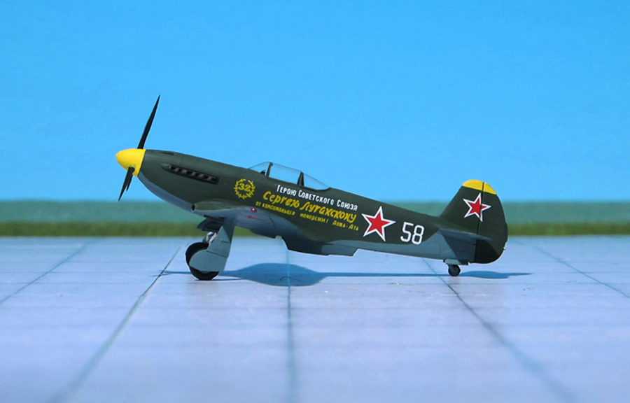
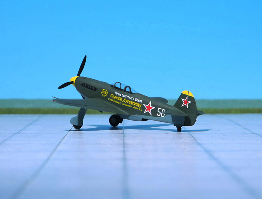
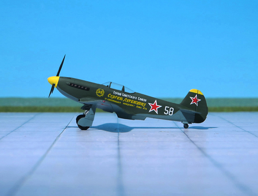
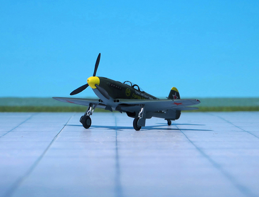
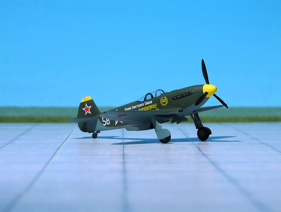
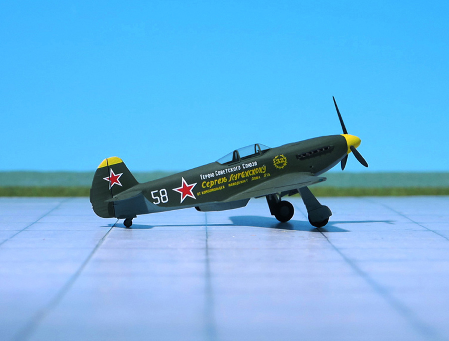
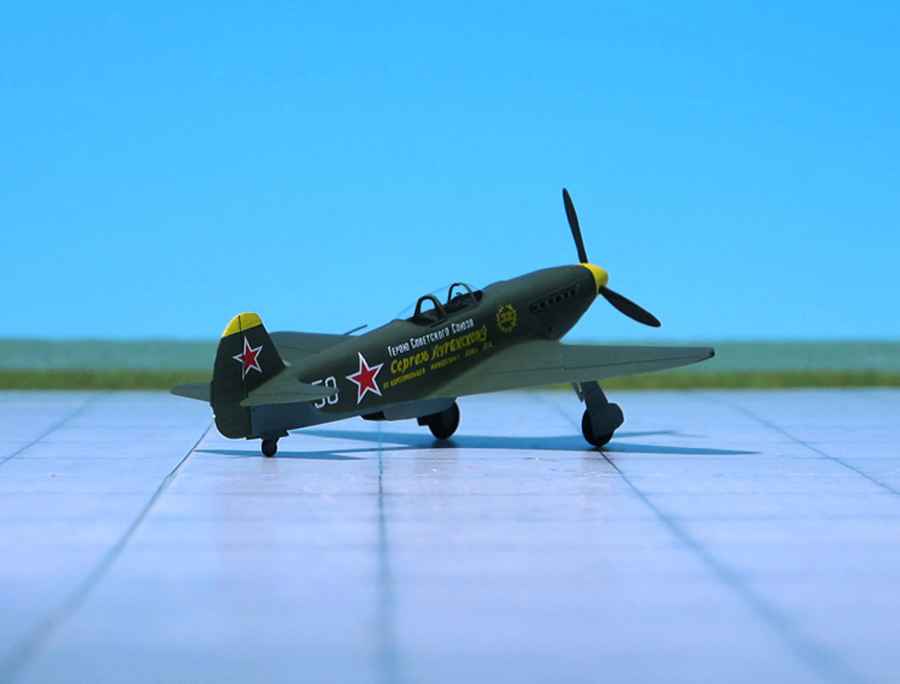
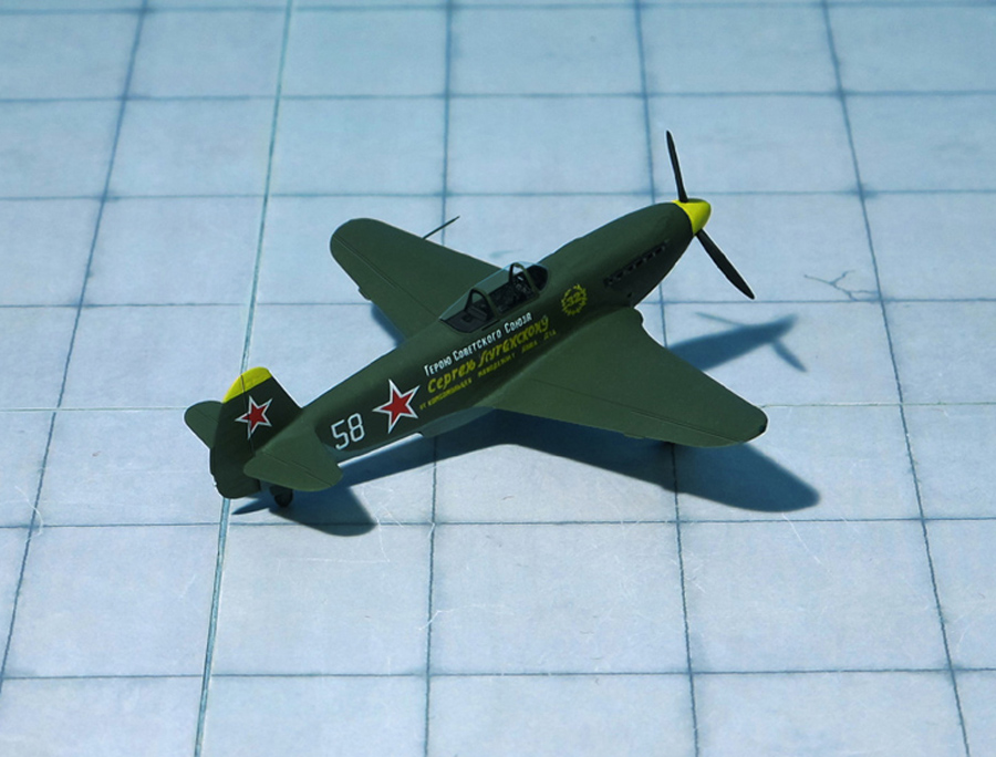
POWER PLANT: One Klimov M-105PF2 liquid-cooled piston engine, rated at 1,290 hp
PERFORMANCE: 401 mph at 13,451 ft
COMMENT: The Yakovlev Yak-3 was a single-engine single-seat WW II Soviet front line fighter aircraft. Robust and easy to maintain, it was much liked by pilots and ground crew alike. It was one of the smallest and lightest major combat fighters fielded by any combatant during the war. Its high power-to-weight ratio gave it excellent performance. It proved a formidable dogfighter.
The origins of the Yak-3 went back to 1941 when the I-30 prototype was offered along with Yakovlev I-26 (Yak-1) as an alternative design. The I-30, powered by a Klimov M-105P engine, was of all-metal construction, using a wing with dihedral on the outer panels. Like the early Yak-1, it had a 20 mm ShVAK cannon firing through the hollow-driveshaft nose spinner and twin 7.62 mm synchronized ShKAS machine guns in cowl mounts ahead of the cockpit on the fuselage, but was also fitted with a ShVAK cannon in each wing. The first of two prototypes was fitted with a slatted wing to improve handling and short-field performance while the second prototype had a wooden wing without slats, in order to simplify production. The second prototype crashed during flight tests and was written off. Although there were plans to put the Yak-3 into production, the scarcity of aviation aluminum and the pressure of the German invasion led to work on the first Yak-3 being abandoned in late fall 1941.
In 1943, Yakovlev designed the Yak-1M which was a lighter version of the Yak-1. It incorporated a wing of similar design, but with smaller surface area and had further aerodynamic refinements, like the new placement of the oil radiator, from the chin to the wing roots (one of the visual differences with the Yak-1, -7, -9). A second Yak-1M prototype was constructed later that year, differing from the first aircraft in that it had plywood instead of fabric covering of the rear fuselage, mastless radio antenna, reflector gunsight and improved armor and engine cooling. The chief test pilot for the project P. M. Stefanovsiy was so impressed with the new aircraft that he recommended that it should completely replace the Yak-1 and Yak-7 with only the Yak-9 retained in production for further work with the Klimov VK-107 engine. The new fighter designated the Yak-3 entered service in 1944, later than the Ya-9 in spite of the lower designation number.
The first 197 Yak-3 were lightly armed with a engine-mount 20 mm ShVAK cannon and one 12.7 mm UBS- synchronized machine gun, with subsequent aircraft receiving a second UBS for a weight of fire of 2.72 kg per second using high-explosive ammunition. All armament was installed close to the axis of the aircraft (cannon mounted in the engine “vee”, and firing through the propeller boss; and synchronized machine guns in the fuselage above the engine), adding to the accuracy and leaving wings unloaded.
Production accelerated rapidly, so that by mid-1946, 4,848 had been built. Before the end of the war it was also flown by Polish Air Forces (of the Polish People’s Army formed in USSR) and after the war ended, it was flown by the Yugoslav Air Force (Ref.: 24).
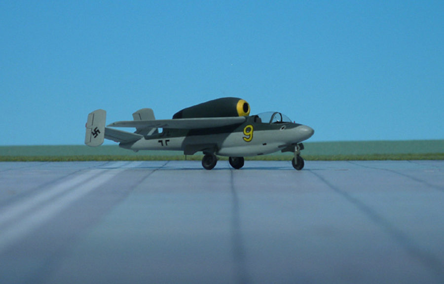
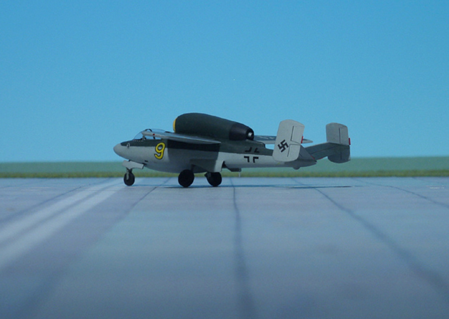
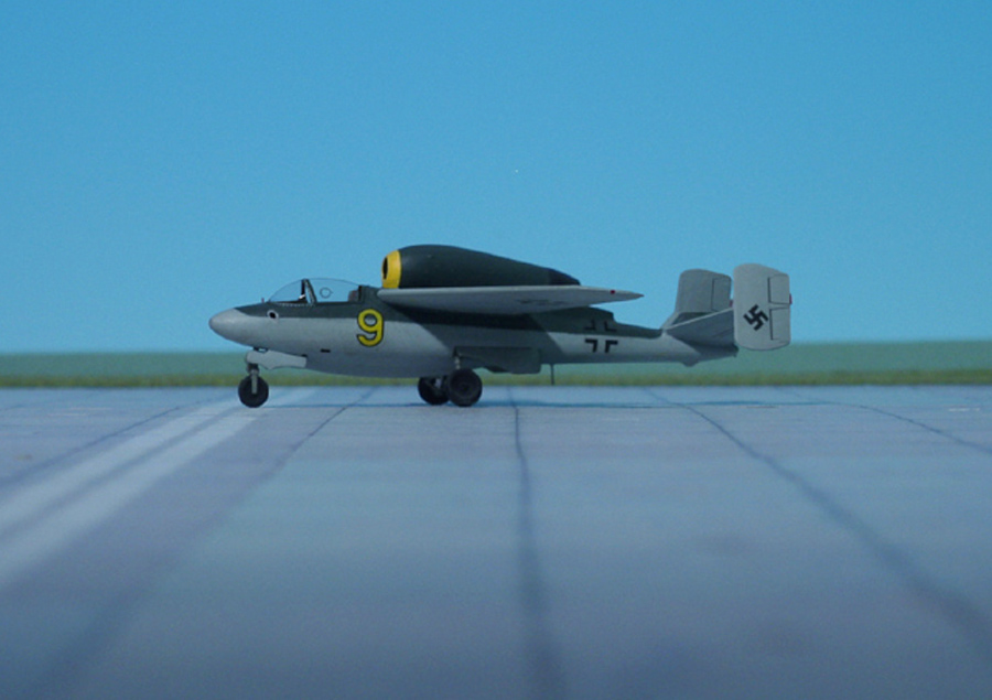
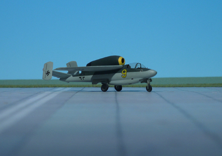
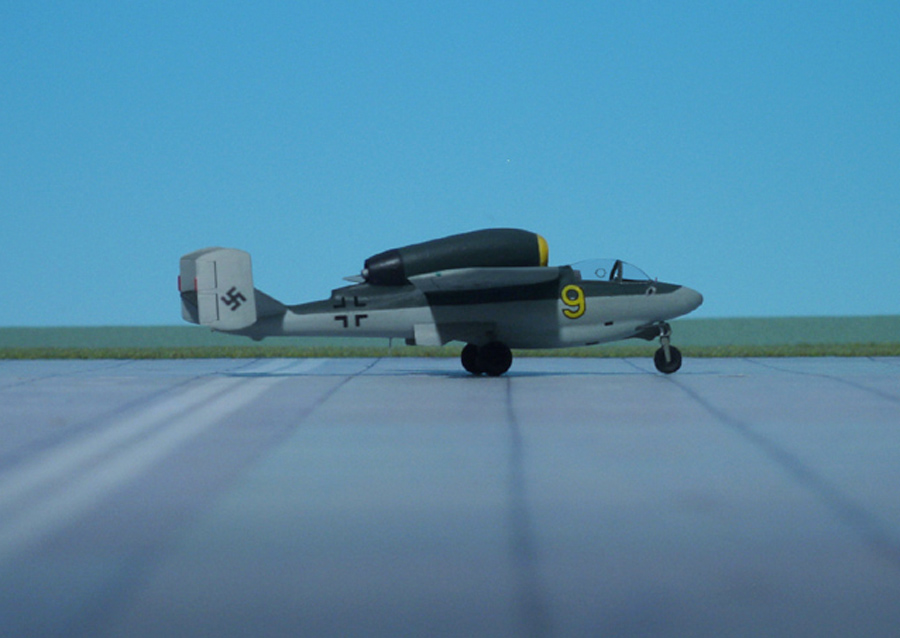
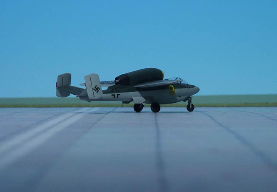
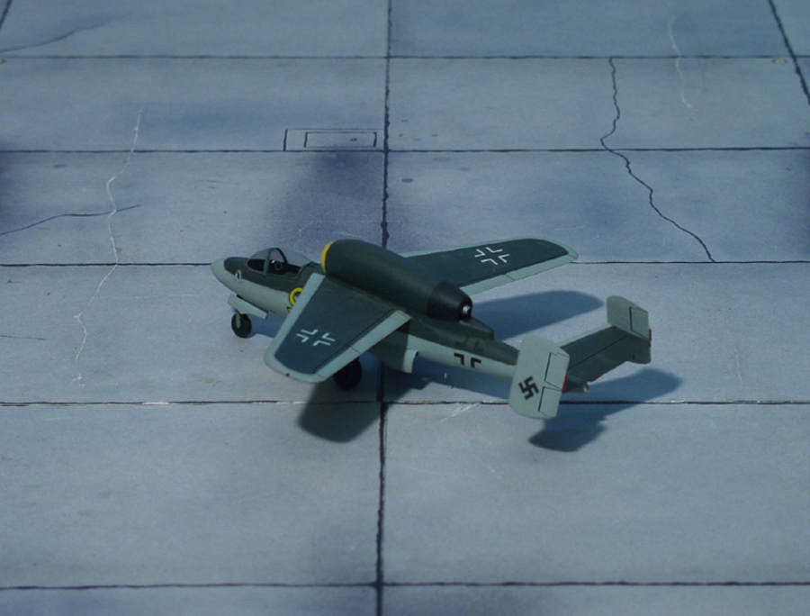
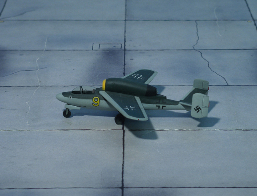
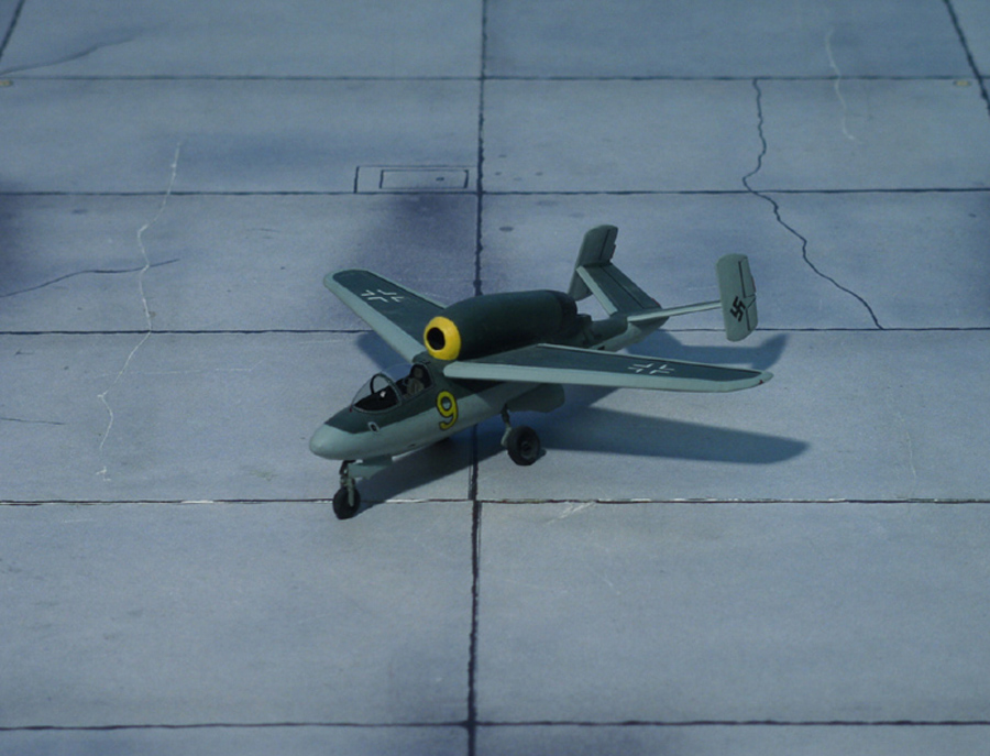
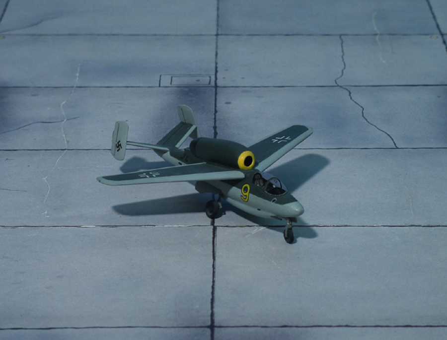
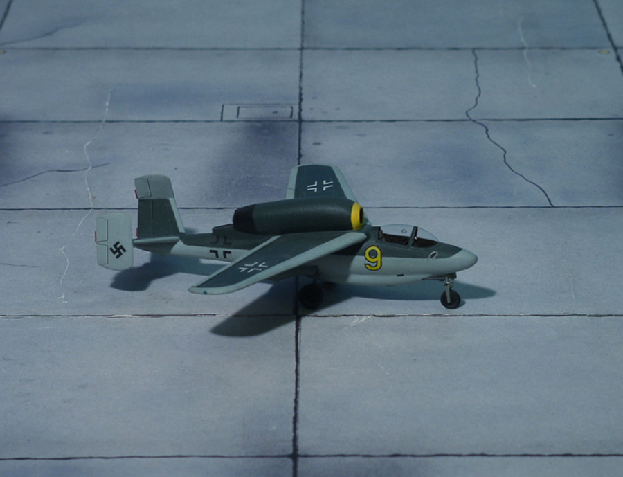
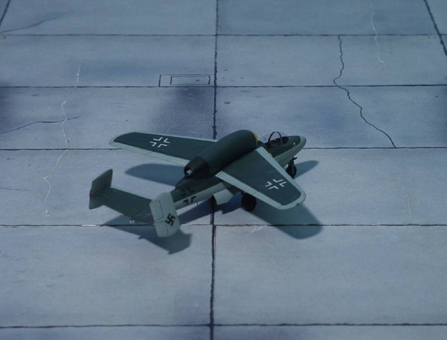
TYPE: Fighter project, forerunner of the Heinkel He 162
ACCOMMODATION: pilot only
POWER PLANT: one Heinkel-Hirth HeS 011 turbojet engine, rated at 1.300 kp thrust
PERFORMANCE: 615 mph in 19615 ft
COMMENT: The summer 1944 saw limitations of the Messerschmitt Me 262 becoming readily apparent. The basic design predated the war. It was heavy and expensive, and required to precious turbojet engines. A cheap high-performance replacement was needed so in July 1944 the RLM issued a requirement for a new single-turbojet high-performance fighter, known as the “1-TL-Jäger”. Germany’s aircraft companies were quick to realise that this was potentially the most important competition in which they had so far had the opportunity to participate. Designing a successful single-seat fighter carries a huge amount of prestige and the most famous firms – Blohm &Voss, Focke-Wulf , Heinkel, Junkers and Messerschmitt – jumped at the chance to create the successor to not only on the me 262 but perhaps also the Bf 109 and Fw 190 too. The engine was to be a Heinkel-Hirth HeS 011 turbojet and the companies were allowed two months to prepare their first designs, Blohm & Voss had two months more time.
On September 1944 the designs were presented at a meeting at Messerschmitt’s Oberammergau facility. It is not known which designed were presented by Messerschmitt and Heinkel, though it is likely that these were one of the earliest versions of the former’s Me P.1101, and the latter’s He P.1073 or a variant of it. Focke-Wulf put forward a twin-boom design Nr.280 it had been working on since early 1944. Blohm & Voss’s design (P.212) was apparently not ready and furthermore it was agreed that Junkers should also be allowed to submit a tender for the requirement.
On the last day of the meeting, a new requirement was suddenly and for most part unexpectedly issued for what would become the “Volksjäger” (Peoples Fighter). This called for a fighter powered by a single BMW 003 turbojet engine that could reach a maximum speed of 466 mph and have an endurance of 30 minutes at full throttle. It also had to be able to operate from poor airfields.
This urgent demand for new single-turbojet fighter designs that could be built in a hurry from low grade non-strategic materials effectively stalled work on the “1-TL-Jäger” competition for several months, particularly Blohm & Voss, Focke-Wulf, Heinkel and Junkers all hastily drafted entries for the “Volksjäger” contest.
The Heinkel He P.1073, originally designed before July 1944 as a fighter with two Junkers Jumo 004C turbojet-engines, one under the nose and one at its back but now altered to fly with just one Heinkel-Hirth HeS 011, was already close to meeting the “Volksjäger” specification. The Heinkel “Volksjäger”-design He P.1073.01.18 was dated from September 1944, just one day after the specification was issued. This only was possible because Heinkel’s design team had several different variants of the design on the drawing board. The documentation describes the He P.1073.01.18 as a “Kleinst-Jäger” (Midget Fighter) and states it is ”a simplification of the design with HeS 011”. It bears remarkable resemblance to what would become the Heinkel He 162 “Spatz” (Sparrow”) except the wings are simpler and both nose wheel and main gear retract forward into the fuselage. Heinkel’s design received a similarly lukewarm reaction, probably because it was based heavily on the company’s already known “1-TL-Jäger” project. But Heinkel’s representatives pointed out that with aircraft such as the Heinkel He 177 bomber no longer in production there was now spare capacity available at its capacious and well-equipped factories. There is some evidence that on September 23rd 1944 Hitler himself ordered the He P.1073 into mass production as Heinkel He 162.
The variant of the He P.1073 design that finally led to the definitive Heinkel He 162 “Volksjäger” is shown here. The design is dated back from September 10th, 1944 and shows the installation of the turbojet engine on the back. The wings are swept back at 35 degree, the tail plane had a positive dihedral and two fins. Under the fuselage on ventral starboard side a streamlined pannier was fitted holding a MK 108 machine canon and two MG 213C machine guns were oblique mounted in the front at both sides of the pilot’s seat. Work on the final version of the Heinkel “Volksjäger began on October 25th, 1944 and its maiden flight took place on December 6th that year (Ref.: Sharp, Dan: Luftwaffe. Secrets Jets of the Third Reich. Mortons Media Group Ltd, Horncastle, 2015).
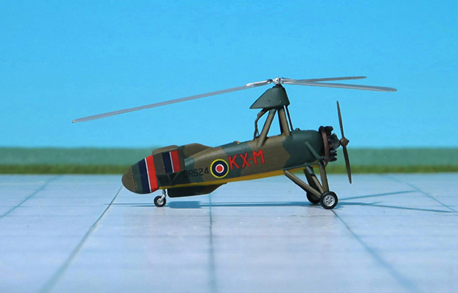
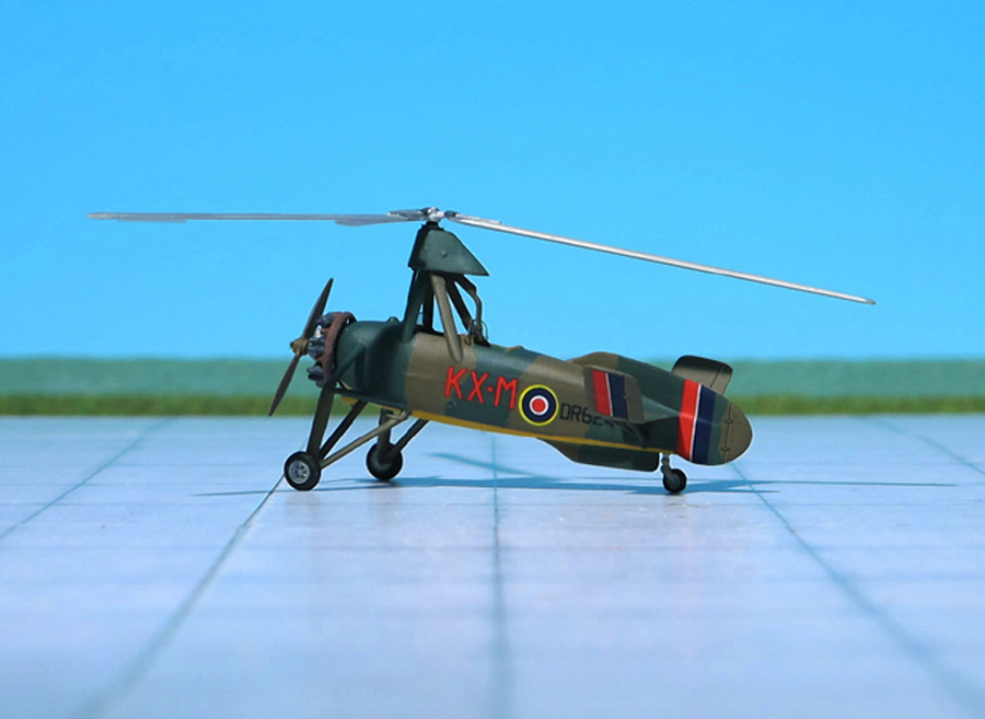
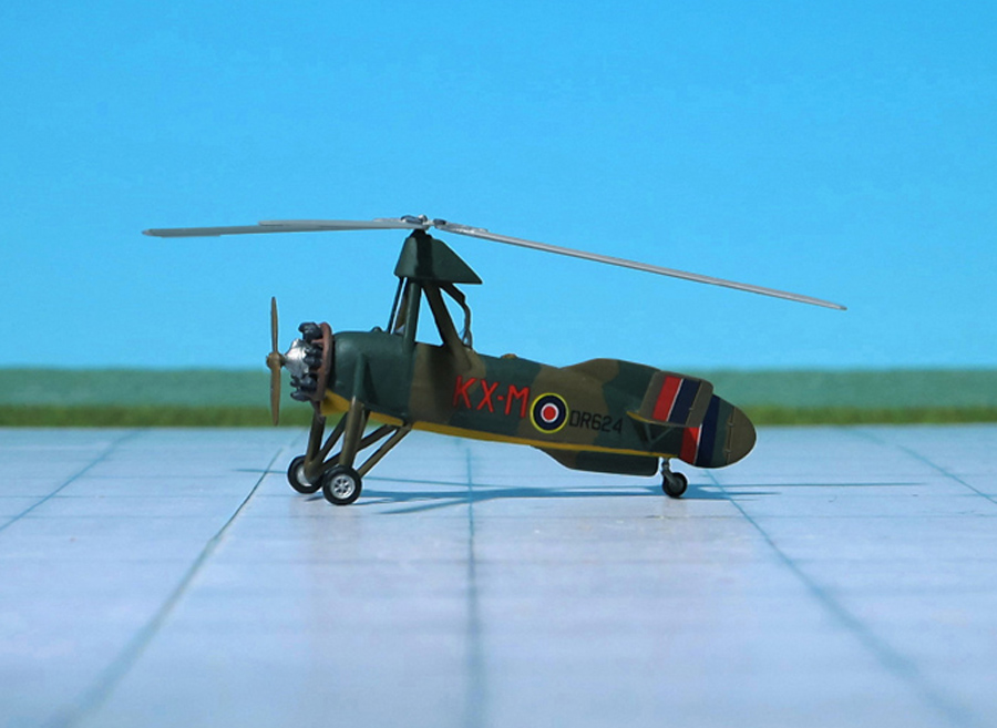
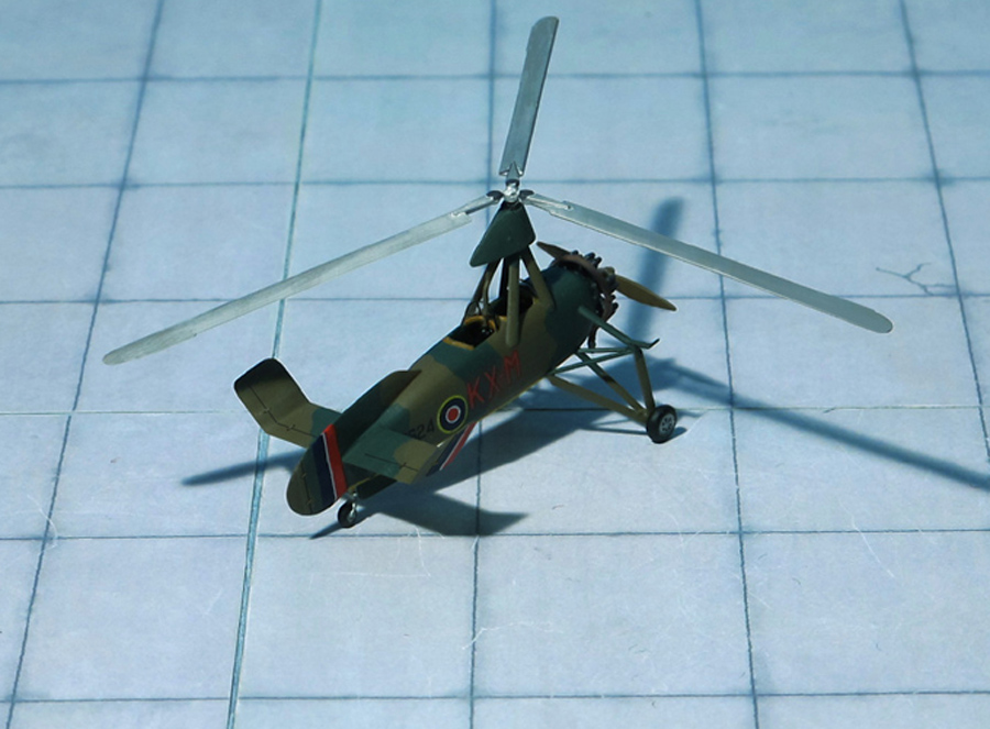
POWER PLANT: One Armstrong Siddeley Genet Major IA radial engine, rated at 140 hp
PERFORMANCE: 110 mph
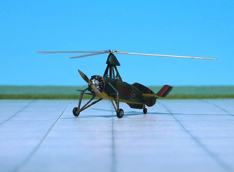
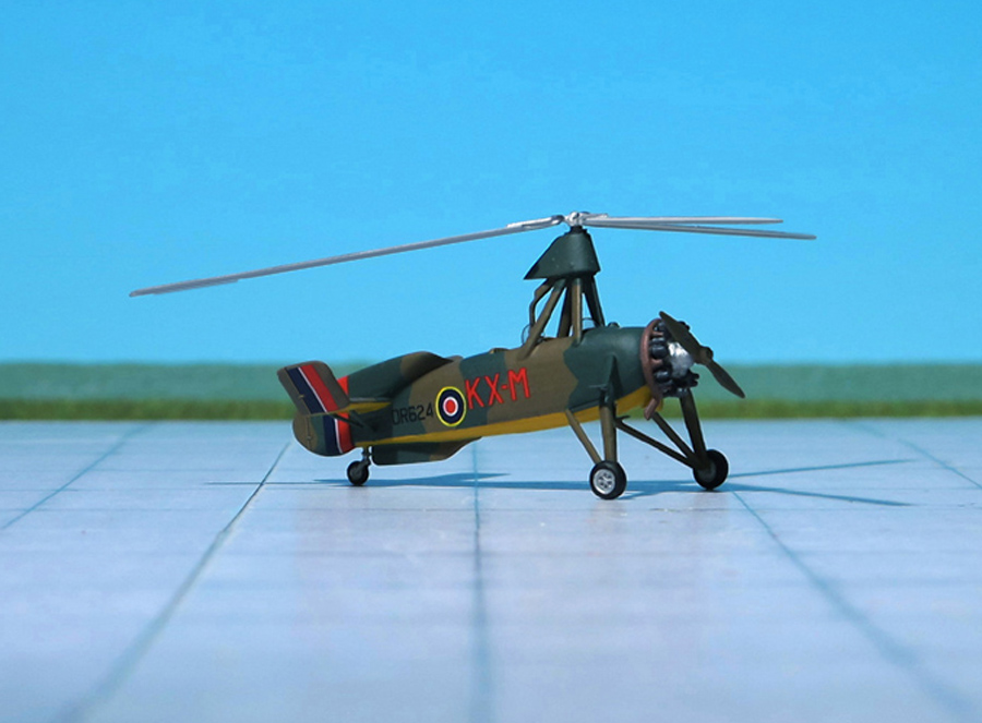
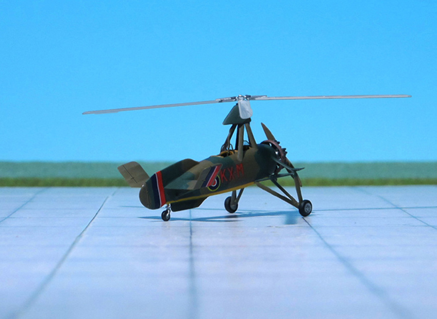
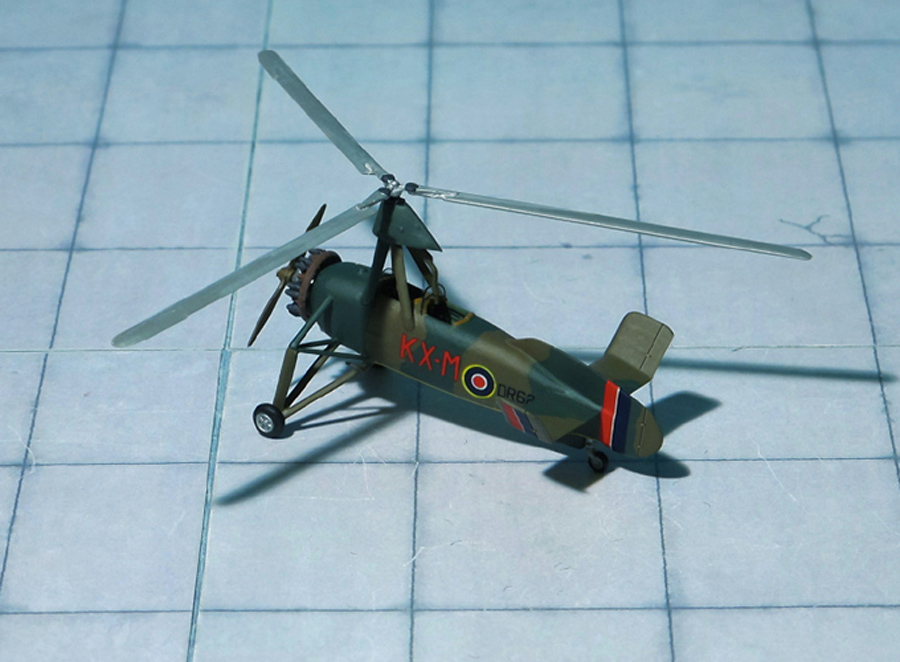
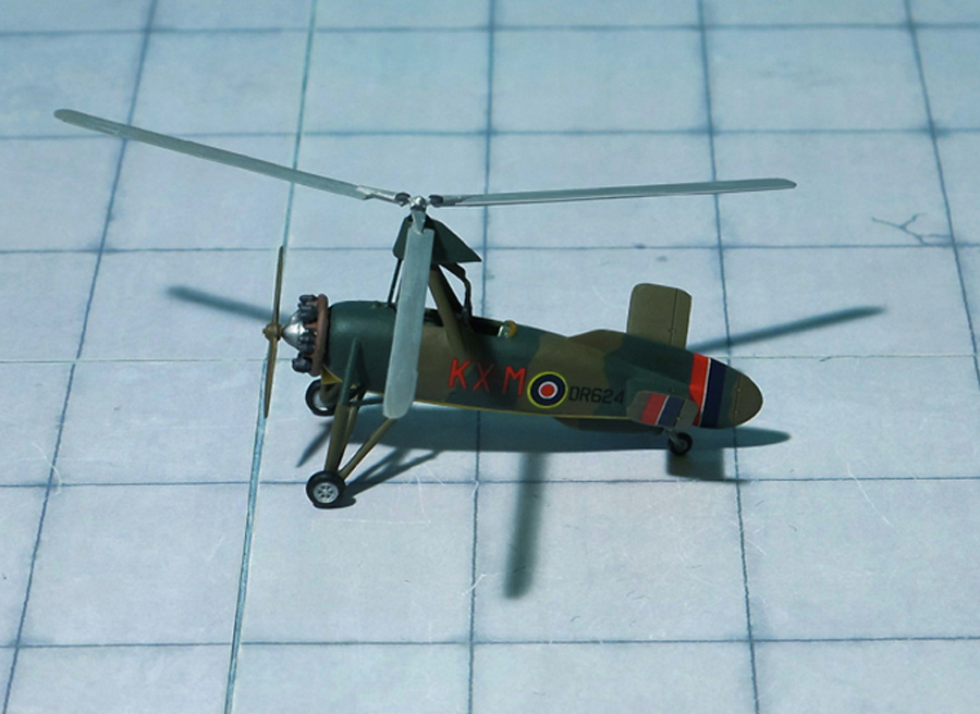
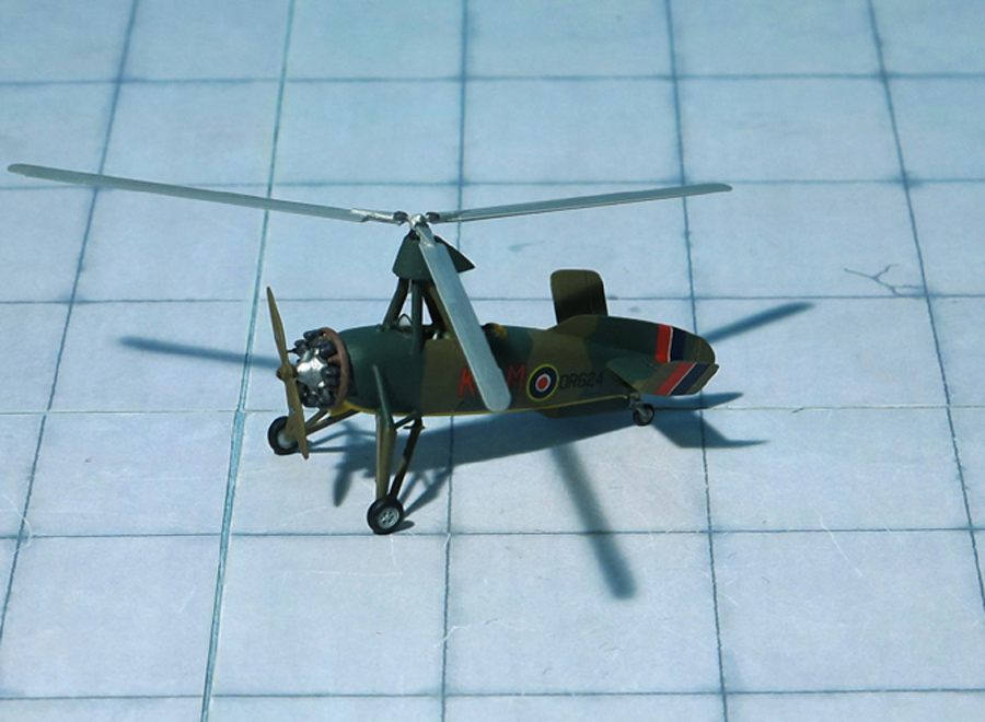
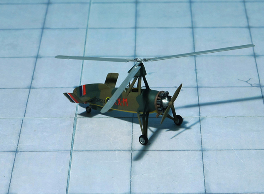
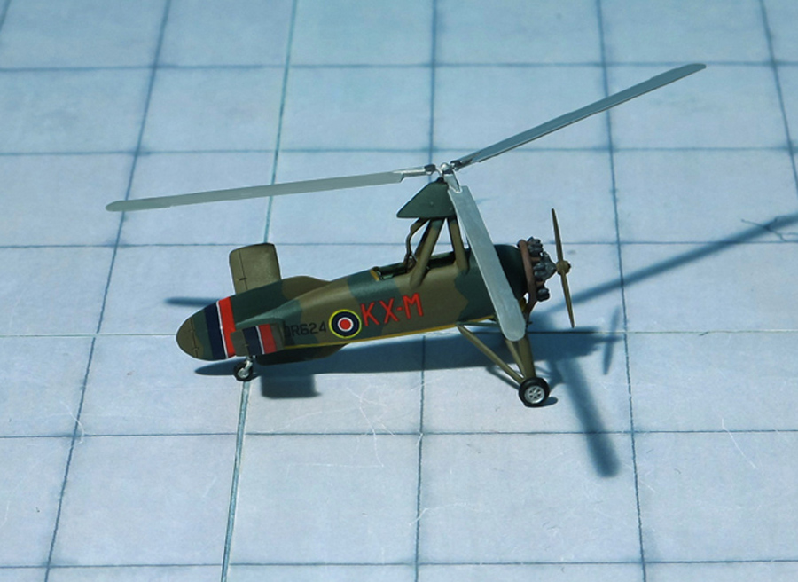
COMMENT: The Avro 671 Rota Mk. I autogyro based on the Cierva C.30 designed by Juan de la Cierva in Spain and built under licence in England by A V Roe & Co Ltd.
Avro obtained the licence in 1934 and subsequently built 78 examples under their model designation, fitted with an Armstrong Siddely Genet Major IA (known in the RAF as the Civet 1) 7-cylinder radial engine producing 140 hp . The first production aircraft was delivered in July 1934.
The first production design in the series was the C.30A, a radial-engined autogyro with a three-blade, 37 ft rotor mounted on an aft-leaning tripod, the control column extending into the rear of the two cockpits. The engine was the five-cylinder, 105 hp Armstrong Siddely Genet Major I. The fabric-covered fuselage carried an unbraced tail plane, without elevators but with turned-up tips. The port side of the tail plane had an inverted aerofoil section to counter roll-axis torque produced by the propeller. As with most autogyros, a high vertical tail was precluded by the sagging resting rotor, so the dorsal fin was long and low, extending well aft of the tail plane like a fixed rudder and augmented by a ventral fin. The wide-track undercarriage had a pair of single, wire-braced legs and a small tail wheel was fitted. This model flew in April 1933. It was followed by four improved machines designated C.30P (P here for pre-production) which differed in having a four-legged pyramid rotor mounting and a reinforced undercarriage with three struts per side. The rotor could be folded rearwards for transport. The C.30P used the more powerful140 hp Armstrong Siddely Genet Major IA radial engine.
Twelve C.30A’s built by Avro for the Royal Air Force (RAF) entered service as the Avro 671 Rota Mk.I. The twelve were delivered between 1934 and 1935. They equipped the School of Army Co-operation at RAF Old Sarum near Salisbury. At least one RAF C.30A was on floats as a “Sea Rota” in January 1935
Many of the surviving civil aircraft were also taken into RAF service between 1939 and 1940. In 1940 they equipped 1448 Flt at RAF Duxford. Later they equipped 529 Sqn at RAF Halton on radar calibration work, disbanded in October 1945, the twelve survivors were sold on to civilian owners (Ref.: 24).
Avro 671 Rota Mk. I
Avro 671 Rota Mk. I
Avro 671 Rota Mk. I
Avro 671 Rota Mk. I
Avro 671 Rota Mk. I
Avro 671 Rota Mk. I
Avro 671 Rota Mk. I
Avro 671 Rota Mk. I
Avro 671 Rota Mk. I
Avro 671 Rota Mk. I
Avro 671 Rota Mk. I
Avro 671 Rota Mk. I
Scale 1:72 aircraft models of World War II
Mit der weiteren Nutzung unserer Webseite erklären Sie sich damit einverstanden, dass wir Cookies verwenden um Ihnen die Nutzerfreundlichkeit dieser Webseite zu verbessern. Weitere Informationen zum Datenschutz finden Sie in unserer Datenschutzerklärung.