All posts by Gunther Arnold

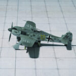
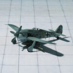
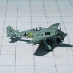
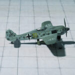
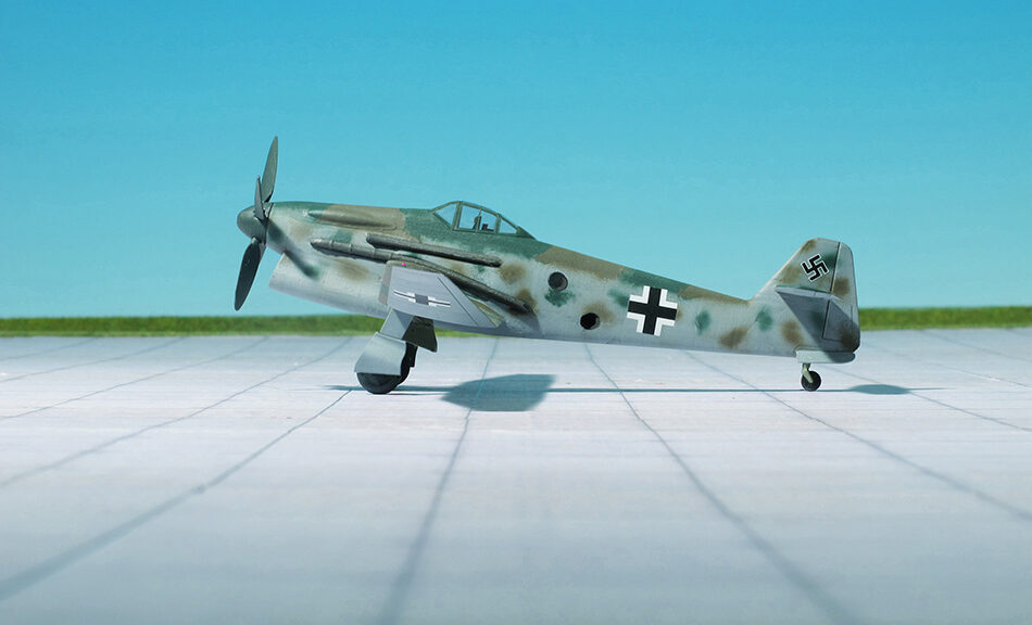
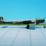
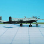
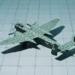
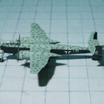
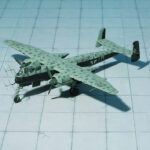
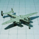
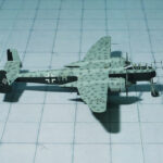
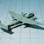
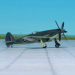
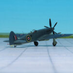
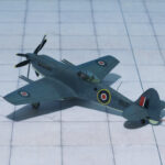
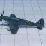
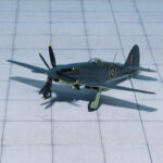
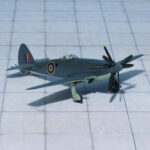
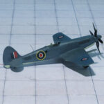
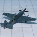
Horten Ho X, 3D-Print (my3dbase)

TYPE: Interceptor, Project

ACCOMMODATION:  Pilot only

POWER PLANT: One BMW 003 turbojet engine, rated at 950 kp thrust, later one Heinkel-Hirth HeS 011 turbojet engine, rated at 1.300 kp thrust

PERFORMANCE: 684 mph

COMMENT: Due to the rapidly deteriorating war conditions in Germany in the last months of WWII, the RLM (Reichs Luftfahrt  Ministerium, German Air Ministry) issued a specification for a fighter project that would use a minimum of strategic materials, be suitable for rapid mass production and have a performance equal to the best piston engined fighters of the time. The Volksjäger (People’s Fighter), as it became known as, was issued on September 8, 1944 to Arado, Blohm & Voss, Fiesler, Focke-Wulf, Junkers, Heinkel,  Messerschmitt and  Siebel. The new fighter also needed to weigh no more than 2000 kg have a maximum speed of 457 mph, a minimum endurance of 30 minutes, a takeoff distance of 500 m (1604′), an endurance of at least 30 minutes and it was to use the BMW 003 turbojet engine.
Although not chosen to submit a design, the Horten Brothers came up with the Ho X that met the specifications laid out by the RLM. Using a similar concept that they had been working on with their Horten IX (Ho 229) flying wing fighter,  the Ho X was to be constructed of steel pipes covered with plywood panels in the center section, with the outer sections constructed from two-ply wood beams covered in plywood. The wing featured two sweepbacks, approximately 60 degrees at the nose, tapering into a 43 degree sweepback out to the wingtips. Control was to be provided by combined ailerons and elevators at the wingtips, along with drag surfaces at the wingtips for lateral control. A single BMW 003E turbojet engine with 900 kp of thrust was housed in the rear of the aircraft, which was fed by two air intakes on either side of the cockpit.  One advantage to this design was that different jet engines could be accommodated, such as the Heinkel-Hirth He S 011 with 1300 kp of thrust, which was to be added later after its development was complete. The landing gear was to be of a tricycle arrangement and the  pilot sat in a pressurized cockpit in front of the engine compartment. Armament consisted of a single MK 108 30mm cannon or a single MK 213 30mm cannon)in the nose and two MG 131 13mm machine guns, one in each wing root.
In order to determine the center of gravity on various sweepback angles, scale models with a 3.05 meter wingspan were built. A full-sized glider was also under construction but was not completed before the war’s end. Further development would have been to add an 240 horsepower Argus As 10C piston engine in a pusher configuration and later the more powerful Heinkel-Hirth He S 011 with 1300 kp of thrust. Due to the ending of hostilities in 1945, the Horten Ho X was not completed (Ref.: 17).

Mitsubishi Ki-46-III KAI (Army Type 100 Air Defence Fighter), (DINAH), (LS-Models)

TYPE: High altitude interceptor

ACCOMMODATION: Crew of two

POWER PLANT: Two Mitsubishi Ha-112-II Army Type 4 radial engines, rated at 1,500 hp each

PERFORMANCE: 404 mph at 19,095 ft

COMMENT: The Mitsubishi Ki-46 was a twin-engine reconnaissance aircraft used by the Imperial Japanese Army in WW II. Its Army  designation was Type 100 Command Reconnaissance Aircraft; the Allied nickname was DINAH.
At the beginning of the conflict the newest version of the Mitsubishi Ki-46-II were able to performe their missions with almost complete freedom from interception as, without the benefit of ground control radar to guide them, the Allied squadron‘ obsolescent fighters failed to reach the elusive Nipponese aircraft in time.
As the production of the Mitsubishi Ki-46-III (Army Type 100 Command Reconnaissance Plane Model 3) gained tempo, a high-altitude interceptor fighter version was developed by the Rikugun Kokugijutsu Kenkyujo (Army Aerotechnical Research Institute) as a stopgap pending production of specialized aircraft. Initially studies for this aircraft bgan in June 1943 and ist development was persued actively from May 1944 onwards. A modification programme was initiated at the Tachikawa Dai-Ichi Kokusho (First Army Air Arsenal at Tachikawa) where the photographic equipment of the standard Ki-46-III was removed. Modifications also included the redesign of the nose to provide space for two 20 mm Ho-5 cannon and the replacement of the top centre fuselage fuel tank by an obliquely mounted forward-firing 37 mm Ho 203 cannon. The first Army Type 100 Air Defence Fighter (Ki-46-III KAI) was completed in October 1944 and, a month later, aircraft of this type were issued to various units operating in defence of Japan. Operational results were disappointing as the Ki-46-III KAIs did not have the climbing speed required for an interceptor, but further developments of this variant resulted in the Army Type 100 Assault Plane (Ki-46-IIIb), of which only a few were built, and the Ki-46-IIIc which remained on the drawing board.
Retaining the Ki-46-III airframe but powered by two Ha-112-II Ru engines fitted with exhaust-driven turbosuperchargers, four Ki-46-IV prototypes were built in 1943-44. With a military rating of 1,100 hp at 33,465 ft, the Ha.112-II Ru gave the aircraft superior performance at altitude. Compared with the Ki-46-III, the Ki-46-IV differed by the installation, in the lower rear portion of the engine nacelles, of the turbosuperchargers, the air intake being methanol-cooled as space restriction prevented the use of an intercooler, and by an increase in internal fuel capacity to 1,977 litres. Tests began in February 1944, but difficulties with the turbosuper-charging system delayed the production of the Army Type100 Command Reconnaissance Plane Model 4a (Ki-46-IVa) and its fighter version, the Ki-46-IVb with nose-mounted cannon, both aircraft being finally deleted from the production priority list.
While the Mitsubishi Ki-46-IIs and Ki-46-IIs operated until the end of the war, two Ki-46-IVs demonstrated in February 1945 that the Dinah was still one of the best reconnaissance aircraft of the time by covering, with the help of strong tailwinds, 1,430 miles at an average speed of 435 mph (Ref.: 1).

Messerschmitt Me P.1112, 3D-Print, (my3dbase)

TYPE: Fighter, Project

ACCOMMODATION:  Pilot only

POWER PLANT: One Heinkel-Hirth HeS 011A0 turbojet engine, rated at 1.300 kp thrust

PERFORMANCE: 680 mph (estimated)

COMMENT: The Messerschmitt P.1112 was a proposed German turbojet fighter, developed by Messerschmitt AG during the closing stages of World War II, and intended for use by the Luftwaffe (German Air Force). The progress of the war prevented the completion of a prototype before the fall of Nazi Germany. Its design, however, had a direct influence on postwar US Navy carrier fighters.
The work on the  Me P.1112 started on February 1945 ( Ten weeks before the unconditional surrender of the Reich!!!!!) after Willy Messerschmitt decided to halt the development of the Messerschmitt Me P.1111, which would have required, as standard equipment, a pressurized cockpit and ejection seat. Designed by the head of the Messerschmitt Project Office W. Vogt, between 3rd and 30th March 1945 as an alternative to the Me P.1111, the Messerschmitt Me P.1112 design was less radical than the Me P.1111 and incorporated the lessons learned from the development of the Messerschmitt Me P.1110 design. Voigt estimated that the Me P.1112 would commence flight testing by mid-1946.
Intended to be powered by a single Heinkel-Hirth HeS 011 turbojet engine, three design concepts of the Me P.1112 were developed. The last proposed design was the Me P.1112/V1 using a V-tail design and fuselage lateral intakes; the two first were the Me P.1112 S/1, with wing root air intakes, and the Me P.1112 S/2, with fuselage lateral intakes, both with a larger, single fin; both designs lacked conventional horizontal stabilizers. All three had a fuselage maximum diameter of 1.1 metres.The aircraft’s wing design was similar in appearance to that of Messerschmitt Me 163 Komet rocket fighter. The pilot was seated in a semi-reclined position, and was equipped with an ejection seat.
A partial mockup of the Me P.1112 V/1, consisting of the aircraft’s forward fuselage section, was constructed in the Conrad von Hötzendorf Kaserne at Oberammergau, Bavaria, but the Messerschmitt facilities there were occupied by American troops in April 1945, before construction of the prototype could begin
Although the Me P.1112 was never completed, follow-on designs were already proposed, even as design work on the type itself was done. These included a proposed night fighter version, which was intended to be fitted with twin engines mounted in the wing roots of the aircraft.
Following WW II, Voigt’s experience in tailless aircraft design was put to use by the Chance Vought Company in the United States, where he was involved in the design of the Chance Vought F7U Cutlass fighter (Ref 24).

Nakajima C6N1-S ‘Saiun’, (Iridecent Cloud), (Myrt). 302nd Kokutai, (Hasegawa)

TYPE: Carrier-based reconnaissance aircraft, land-based night fighter

ACCOMMODATION:  Crew of two

POWER PLANT: One Nakajima NK9B Homare 11 air-cooled radial engine, rated at 1,991 hp

PERFORMANCE: 380 mph at 20,000 ft

COMMENT: The Nakajima C6N Saiun ( “Iridecent Cloud“) was a carrier-based reconnaissance aircraft  used by the Imperial Japanese Navy Air Service in World War II. Advanced for its time, it was the fastest carrier based aircraft put into service by Japan during the war. The Allied reporting name was Myrt.
The Nakajima C6N originated from a 1942 Imperial Japanese Navy specification for a carrier-based reconnaissance plane with a top speed of 403 mph at 19,700 ft and a range of 2,500 nautical miles. Nakajima’s initial proposal, designated N-50, was for a craft with two 1,000 hp engines housed in tandem in the fuselage, driving two propellers mounted on the wings. With the development of the 2,000 hp class Nakajima Homare engine, the dual powerplant configuration was abandoned and Nakajima decided on a more conventional single-engine layout. Unfortunately the new Homare’s power output was less than expected, and the design had to be optimized in other areas. The resulting aircraft was designed around a long and extremely narrow cylindrical fuselage just large enough in diameter to accommodate the engine. The crew of three sat in tandem under a single canopy, while equipment was similarly arranged in a line along the fuselage. The C6N’s low-mounted laminar flow wing housed fuel tanks and was fitted with both Fowler and slit flaps and leading-edge slats which lowered the aircraft’s landing speed to ease use aboard aircraft carriers. Like Nakajima’s earlier B6N Tenzan torpedo bomber, the vertical stabilizer was angled slightly forward to enable tighter packing on aircraft carrier decks.
The C6N’s first flight was on May 1943, with the prototype demonstrating a speed of 397 mph. Performance of the Homare engine was disappointing, especially its power at altitude, and a series of 18 further prototypes and pre-production aircraft were built before the Saiun was finally ordered into production in February 1944.
Although designed for carrier use, by the time it entered service in September 1944 there were few carriers left for it to operate from, so most C6Ns were flown from land bases. Its speed was exemplified by a telegraph sent after a successful mission: “No Grummans can catch us.” The top speed of the Grumman F6F Hellcats was indeed of the same level, so overtaking a Saiun was out of the question.
A total of 463 aircraft were produced. A single prototype of  turbocharged development mounting a 4-blade propeller was built; this was called the C6N2 Saiun-kai. Several examples of a night fighter version C6N1-S with oblique-firing (Schräge Musik configuration) single 30 mm (or dual 20 mm) cannon were converted from existing C6N1s. As Allied bombers came within reach of the Japanese home islands, a first class night fighter was required. This led Nakajima to develop the C6N1-S by removing the observer and replacing him with two 20 mm cannons. The C6N1-S’s effectiveness was hampered by the lack of air-to-air radar, although it was fast enough to enjoy almost complete immunity from interception by Allied fighters. The 30 mm version was only used to attack Boeing B-29 Superfortress once, on August 1, 1945. The destructive power of the Type 2 cannon extended to twisting the skin of the Saiun’s lightweight fuselage.
A torpedo carrying C6N1-B was also proposed, but was not needed after most of Japan’s aircraft carriers were destroyed.
Despite its speed and performance, on 15 August 1945 a C6N1 happened to be the last aircraft to be shot down in World War II. Just five minutes later, the war was over and all Japanese aircraft were grounded (Ref. 24).

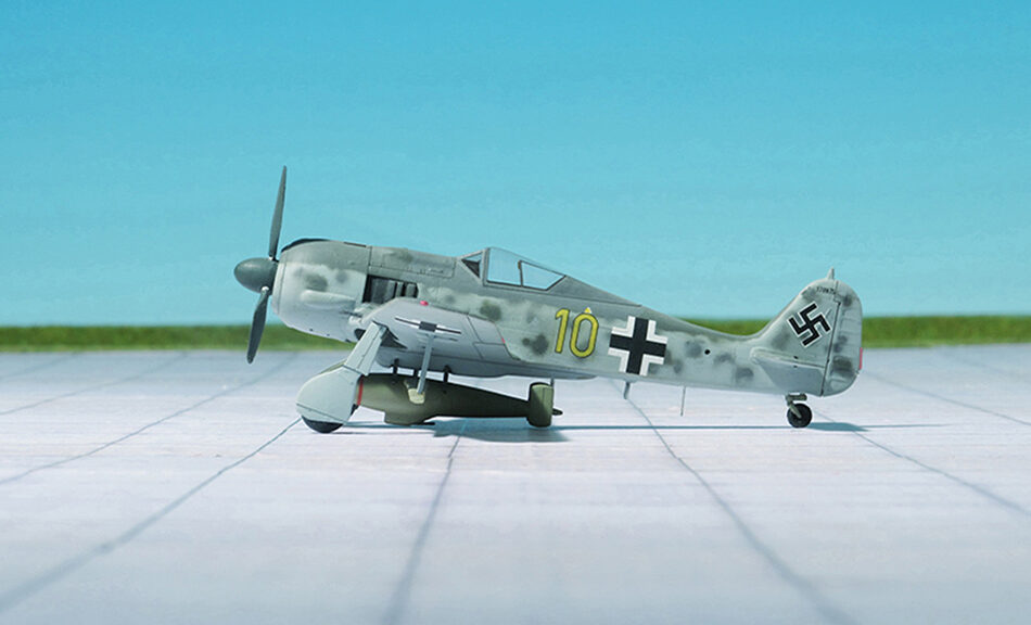
Focke-Wulf Single-Seat Fighter with BMW P.8011 (My3dbase.com)

TYPE: High-altitude Interceptor

ACCOMMODATION: Pilot in pressurized cockpit

POWER PLANT: One BMW P.8011 radial engine with two turbochargers, rated at 2.900 hp

PERFORMANCE: 451 mph in 26.215 ft

COMMENT: By the beginning of 1942, the Focke-Wulf Fw 190A was established in production and service, and most of the more serious shortcomings that has revealed themselves during the fighter’s gestation had been ironed out. A solution had still to be found out. However, the performance of the aircraft at high altitudes was inadequate. So one of the preproduction airframe was fitted with a nitrous oxide injection or GM 1 system for use above the rated altitude of the engine. The nitrous oxide, which was retained under pressure in liquid form in a tank aft of the cockpit, provided additional oxygen for the engine, but sometimes also acting as an antidetonant.
Flight testing proved disappointing. Effective combat altitude was boosted to some 26.000 ft, but insufficient nitrous oxide could be carried to increase power for more than brief periods, difficulties were experienced in lagging the pipelines, and the weight of the system, with its compressed air cylinders and heavily-lagged GM 1 tank, was almost as much as the total gun armament of the standard fighter.
Focke-Wulf was convinced that the desired performance could not be achieved with the BMW 801, and that the engine should be replaced by a liquid-cooled power plant. The design team with Prof. K. Tank favored the Daimler-Benz DB 603, but this engine was viewed with disfavor by the RLM, having been developed by Daimler-Benz without official sanction. Tank was informed that the improved performance now being sought should be achieved with developments of the BMW 801 air-cooled radial.
Meanwhile BMW was working on the BMW 802, a large air-cooled radial engine consistig of two rows of nine cylinders. It was essentially an 18-cylinder version of the 14-cylinder BMW 801. The BMW 802 emerged with an almost identical displacement to the American 18-cylinder Wright R-3350 Duplex Cyclone and somewhat larger than the British Bristol Centaurus. Although promising at first, development dragged on and the project was eventually cancelled.
Another idea to improve the performance was to bolt two BMW 801s back to back. Although seemingly a simple concept, the resulting, 83.5 litre displacement BMW 803 was in fact fantastically complicated. The power of the engine could only practically be used in extremely large propellers, or, as selected, a contra-rotating pair of propellers. This required a large gearbox on the front of the engine, which combined with the layout of the cylinders, left no room for airflow over the cylinders. This demanded the addition of liquid cooling.
Based on this concept of a twin-engine a further improvement led to the BMW P.8011. This engine was, able to produce 2.900 hp at take-off. The supercharger was replaced by two gas turbines enclosed in an aerodynamic engine cowling and driving two contra-rotating three-bladed propellers.
These engines were too heavy and powerful for the standard Focke-Wulf Fw 190 airframe. It was necessary to design a heavier airplane. The answer was a 125% scaled-up version of the Fw 190 with a wing of 42,7 ft span ad 371 sqft surface. The BMW P. 8011 was 38.7 ft long and the maximum weight was more than 11.900 lbs.
This new fighter was provided with an armored pressure cabin and used as high-altitude interceptor. Due to the war situation the project was cancelled in late 1944.
This monster fighter lacked any official designation and was only known as “Focke-Wulf Einsitzer mit BMW P.8011” (Focke-Wulf Single-seater with BMW P. 8011). By the end of 1944 in an article by General “Hap” Arnold, USAAF, published on 29 May 1944 in “Aviation News” refers it as Focke-Wulf Fw 290. But that is an error because the RLM Number “290” was given to the Junkers Ju 290 four-engine maritime control and transport aircraft (Ref.: 7, 24).

Yakovlev Yak-3, 303rd IAP (Airfix)

TYPE: Fighter

ACCOMMODATION:  Pilot only

POWER PLANT: One Klimov VK-105PF2 liquid-cooled piston engine, rated at 1,290 hp

PERFORMANCE: 401 mph at 13,500 ft

COMMENT: The Yakovlev Yak-3 was a single-engine single-seat World War II Soviet front line fighter aircraft. Robust and easy to maintain, it was much liked by pilots and ground crew alike. It was one of the smallest and lightest major combat fighters fielded by any combatant during the war. Its high power-to-weight ratio gave it excellent performance. It proved a formidable dogfighter.
In 1943, a group of designers headed by Alexander Sergeyevich Yakovlev designed the Yak-3, a further development of the proven Yak-1 aimed at improving survivability, flight characteristics and firepower, which required a lower weight, a higher-power engine and therefore, faster speed.
The first of two prototypes had a slatted wing to improve handling and short-field performance while the second prototype had a wooden wing without slats in order to simplify production and save aluminium. The second prototype crashed during flight tests and was written off. Although there were plans to put the Yak-3 into production, the scarcity of aviation aluminium and the pressure of the Nazi invasion led to work on the first Yak-3 being abandoned in late 1941.
In between 1942 and 1943, Yakovlev built the Yak-1M, a prototype that would ultimately lead to the Yak-3, coupled with the VK-105PF2, the latest iteration of the VK-105 engine family, where “P” indicated support for an autocannon that fires between the engine banks, through the hollow propeller shaft – mounting. It incorporated a wing of similar design but with smaller surface area (17.15 to 14.85 m2 , and had further aerodynamic refinements, like the new placement of the oil radiator, from the chin to the wing roots (one of the visual differences with the Yak-1, Yak-7, Yak-9). A second Yak-1M (originally meant as a “backup”) prototype was constructed later that year, differing from the first aircraft in that it had plywood instead of fabric covering of the rear fuselage, mastless radio antenna, reflector gunsight and improved armour and engine cooling.
The first 197 Yak-3 were lightly armed with a single 20 mm SHVAK cannon and one 12.7 mm UBS synchronized machine guin, with subsequent aircraft receiving a second UBS for a weight of fire of 2.72 kg (6.0 lb) per second using high-explosive ammunition. All armament was installed close to the axis of the aircraft with a cannon mounted in the engine “vee” firing through the propeller boss, synchronised machine guns in the fuselage, helping accuracy and leaving wings unloaded.
Lighter and smaller than Yak-9 but powered by the same engine, the Yak-3 was a forgiving, easy-to-handle aircraft loved by both novice and experienced pilots and ground crew as well. It was robust, easy to maintain, and a highly successful dog-fighter. It was used mostly as a tactical fighter, flying low over battlefields and engaging in dogfights below 13,000 ft.
Unresolved wartime problems with the Yak-3 included plywood surfaces coming unstuck when the aircraft pulled out of a high-speed dive. Other drawbacks of the aircraft were short range and poor engine reliability. The pneumatic system for actuating landing gear, flaps and brakes, typical for all Yakovlev fighters of the time, was troublesome. Though less reliable than hydraulic or electrical alternatives, the pneumatic system was preferred owing to the weight saving (Ref.: 24).

Lippisch Li P.01-117, (A+V-Models, Resin)

TYPE: Interceptor, Project

ACCOMMODATION: Pilot, in prone position

POWER PLANT: One BMW 109-510 or one Walter HWK 109-509 liquid-fuel rocket engine, each rated between 300 and 1,500 kp thrust

PERFORMANCE: 550 mph (estimated)

COMMENT: This Lippisch Li P.01-117 project dates from July and August 1941 after Alexander Lippisch and his design team moved to the Messerschmitt A.G. in Augsburg in early 1939. At that time a trio of Lippisch Li  P. 01 designs were conceptualized within three weeks – the P.01-117 on July 22, the P.01-118 on August 3 and the P.01-119 on August 4.
The first design P.01-117 featured a cockpit where the pilot laid on a couch, chin up and head forward, the second boasted a novel tilting seat arrangement to improve the pilot’s visibility during a steep near-vertical climb, and the third had a pressure cabin for high altitude operations. Each of them was to be powered by a BMW or Walter HWK rocket engine but only the P.01-118 also had a second rocket engine to provide greater endurance for level flight. From this point on, all mention of the P.01 ceased and the project continued as the Messerschmitt Me 263.
The Lippisch Li P.01-117 was a tailless aircraft, with a swept wing at approximately 35 degrees. The overall plan resembled the later Messerschmitt  Me 163 “Komet” rocket-powered fighter. The fuselage held the fuel tanks and a rocket engine was mounted in the rear fuselage. A pressurized cockpit was located in the aircraft’s extreme nose, and the pilot faced the front in a prone position and looked out through a blister of bulletproof glass. Up to six MG 151/20 20mm cannon were mounted around the nose of this aircraft. Take-off was accomplished by means of a releasable trolley, sometimes additionally boosted by two solid fuelled Schmidding 109-563 take-off rockets with 500 kp thrust each. Additional jettisonable solid-fuelled rockets could be attached to the fuselage. Landing was to be accomplished on a retractable skid, as was later done on the Messerschmitt Me 163. This design went no further than the preliminary design phase, but the Messerschmitt Me 163 went into production and was used operationally by the Luftwaffe (Ref.: 20).

Kokusai Ki-59 („Theresa“), Hamamatsu Army Bomber School, (A+V Models)

TYPE: Tranport aircraft, trainer

ACCOMMODATION:  Crew of three plus eight passengers

POWER PLANT: Two Hitachi Ha-13a radial engine , rated at 450 hp each

PERFORMANCE: 186 mph

COMMENT: The Kokusai Ki-59 was an early 1940s light transport monoplane built by Nippon Kokusai Koku Kogyo K.K. for the Imperial Japanese Army as a development of the Teradako-ken TK-3 which had first flown in 1938.
The Teradako-ken TK-3 was a prototype eight-to-ten passenger light transport monoplane built by Nippon Koku Kogyo Kabushiki Kaisha as a short-range transport for civil use at the request of Imperial Japanes Airways to replace its aging fleet of Airspeed Envoys and Fokker Super Universals. The first of two prototypes flew in June 1938, but was unable to meet the required performance requirements and the project was cancelled. In 1939, the Imperial Japanese Army revived the project to meet its urgent requirement for a light transport and liaison aircraft and instructed Nippon to develop the design as the Ki-59.
The Ki-59 was a high-wing cantilever monoplane with a fixed tailwheel landing gear and conventional single vertical tail surfaces. It was powered by two 450 hp Hitachi Ha-13a radial engines and other modifications to the design were made to meet Army requirements. The Ki-59 was ordered into production in 1941 with the designation Army Type 1 Transport, and an additional 59 units were produced. After the start of World War II, the aircraft was given the Allied reporting name „Theresa“. Despite the more powerful engines and modifications sponsored by the Japanese Army, the Ki-59 remained a poor performer and saw little service before being replaced by the more capable Tachikawa Ki-54. A small number were transferred to Manchukuo National Airways.
Near the end of 1941 one Ki-59 was modified into a glider with the removal of the engines and the landing gear replaced by underfuselage skids. It was designated the Ku-8-I or Army Experimental Glider. This was further developed as the Ku-8-II or Army Type 4 Large Transport Glider which became the only operationally used Japanese assault glider. It was named „Gander“ by the Allies (Ref.: 24).

Lippisch P.01-115, (Unicraft Models, Resin)

TYPE: Interceptor, Project

ACCOMMODATION: Pilot only

POWER PLANT: One BMW P-3304/109-002 turbojet engine and an undetermined Walter rocket engine, thrust of each engine unknown

PERFORMANCE: No data available

COMMENT: The Lippisch Li P.01-115 was another design under the Li P.01 series, all designed by Alexander Lippisch and his team while at Messerschmitt A.G.
Dated July 2, 1941, the Li P.01-115 had a similar plan form to the others in the P.01 series (which were similar to the Messerschmitt Me 163 rocket fighter). The fuselage held the armament, fuel and power plants. This was one of the first designs to feature a dual powered fighter. A small BMW P-3304/109-002 turbojet engine was located in the upper rear fuselage and was fed by an air intake on top of the fuselage. In addition, a BMW 109-510 rocket engine was mounted beneath the turbojet and provided takeoff and perhaps emergency power. The wings were swept back at 27 degrees, and only a single vertical tail and rudder was to be fitted. In this tailless configuration, the pilot sat in a cockpit in the front of the plane.  For take-off, a pair of wheels, each mounted onto the ends of a specially designed cross-axle, were needed due to the weight of the fuel, but the wheels, forming a take-off dolly under the landing skid, were released shortly after take-off. and landing was accomplished on a retractable skid. Two forward-firing fixed MG 151 15mm cannon located in the forward lower fuselage comprised the armament.
As with other designs in the Lippisch P.01 series, this design went no further than the drawing board stage. All work was later devoted to the Messerschmitt Me 163 “Komet” and later variant rocket fighters (Ref.: 20).

Boeing B-29 Superfortress ‘Bockscar’, 393rd Bombardment Squadron, 509th Composite Group. Before the Nagasaki Mission with Pumpkin Bomb (Post # I)

BOEING B-29A SUPERFORTRESS ‚BOCKSCAR‘

Bockscar, sometimes called Bock’s Car, is the name of the United States Army Air Force (USAAF) B-29 bomber that dropped a Fat Man, a plutonium implosion-type nuclear weapon, over the Japanese city of Nagasaki during World War II in the second – and most recent – nuclear attack in history.
Bockscar, B-29-36-MO 44-27297, Victor number, (unit-assigned identification number) # 7, was built by the Glenn L. Martin Company at its bomber plant in Bellevue, Nebraska and one of 15 Silverplate B-29, a Block 35 aircraft, after modification re-designated “Block 36”. It was delivered to the United States Army Air Forces on 19 March 1945 and in April assigned to the 393rd Bombardment Squadron, 509th Composite Group to Wendover Army Air Field, Utah, and was named after Captain Frederick C. Bock.
Silverplate involved extensive modifications to the B-29 to carry nuclear weapons. The bomb bay doors and the fuselage section between the bomb bays were removed to create a single 33-foot bomb bay. British suspensions and bracing were attached for both shape types, with the gun-type (Little Boy) suspension anchored in the aft bomb bay and the implosion type (Fat Man) mounted in the forward bay. Weight reduction was also accomplished by removal of gun turrets and armor plating. These B-29s also had an improved engine, the Wright R-3350-41. The Silverplate aircraft represented a significant increase in performance over the standard variants.
Captain Frederick C. Bock and crew C-13, flew to Wendover Army Air Field in April. The name chosen for the aircraft, and and the nose art painted on it after the mission, was a pun on the name of the aircraft commander. It left Wendover on 11 June 1945 for Tinian, where it arrived 16 June. It was originally given a circle outline around an arrowhead pointing forward tail marking as used by the 509th Composite Group. Bockscar was used in 13 training and practice missions from Tinian, and three combat missions in which it dropped Pumpkin bombs on industrial targets in Japan, in which Bock’s crew bombed Niihama, Musashimo and Koromo.

Pumpkin bomb

 PUMPKIN BOMBS

Pumpkin bombs“ were conventional aerial bombs developed by scientists of the Manhattan Project and used by the United States Army Air Forces against Japan during WW II. It was a close replication of the „Fat Man“ plutonium bomb with the same ballistic and handling characteristics, but it used non-nuclear conventional high explosives. It was mainly used for testing and training purposes, which included combat missions flown with pumpkin bombs by the 509th Composite Group. The name “pumpkin bomb” was the term used in official documents from the large, fat ellipsoidal shape of the munition casing instead of the more usual cylindrical shape of other bombs, intended to enclose the „Fat Man’s“ spherical “physics package” (the plutonium implosion nuclear weapon core).
Pumpkin bombs“ were produced in both inert and high-explosive variants. The inert versions were filled with a cement-plaster-sand mixture that was combined with water to 1.67 to 1.68 grams per cubic centimetre, the density of the composition high-explosive versions. The filler of both variants had the same weight (2,900 kg) and weight distribution as the inner spherical “physics package” of the „Fat Man“ plutonium bomb.
A total of 486 live and inert training bombs were eventually delivered, the 509th Composite Group dropped a total of 49 bombs on 14 Japanese targets (Ref. 24).