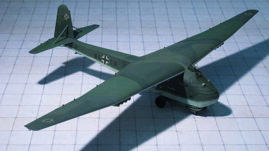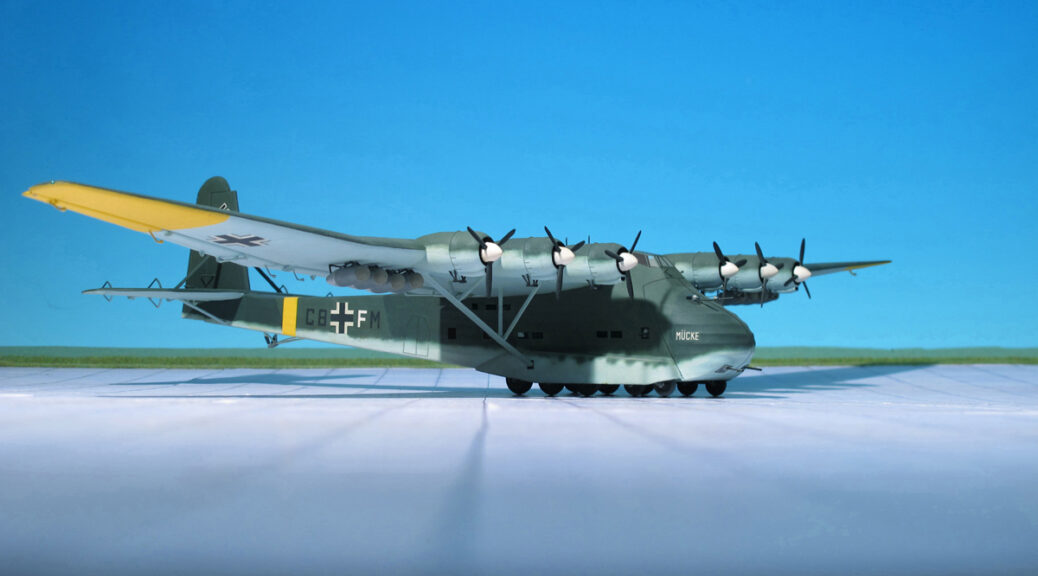
TYPE: Military transport aircraft
ACCOMMODATION: Crew of five plus 130 troops or 10,000–12,000 kg payload
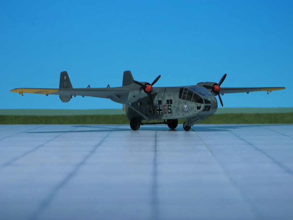
POWER PLANT: Six Gnome-Rhone 14N radial engines, rated at 1,164 hp; each
PERFORMANCE: 177 mph
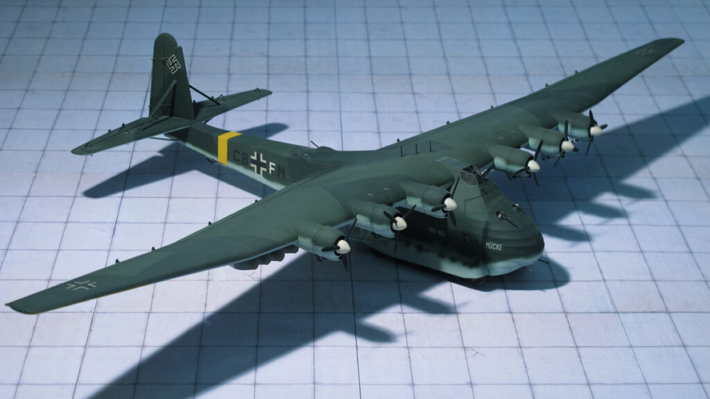
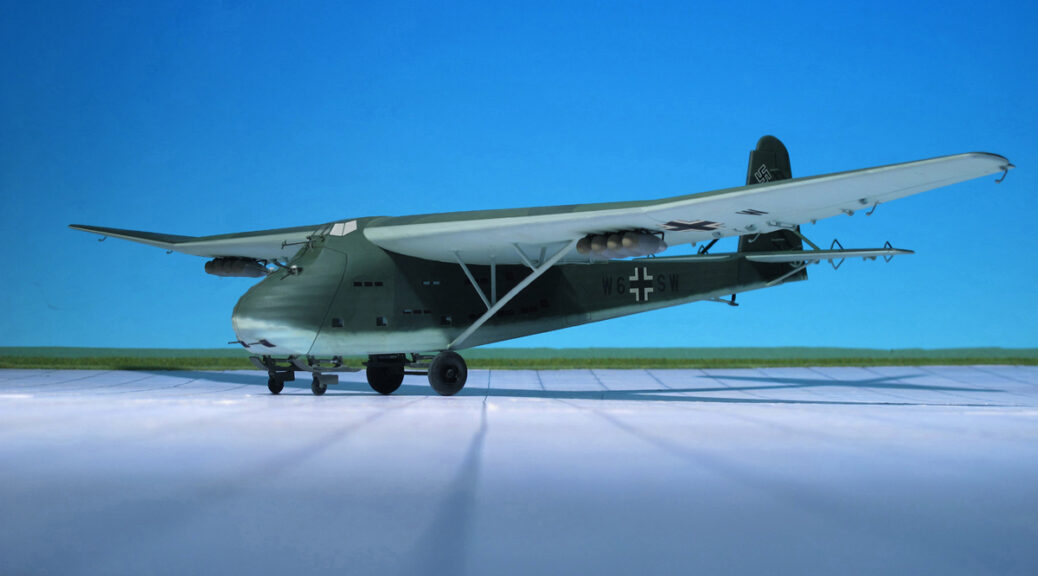
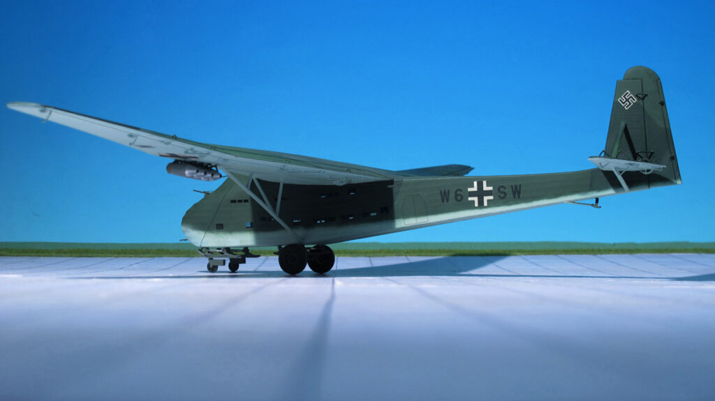
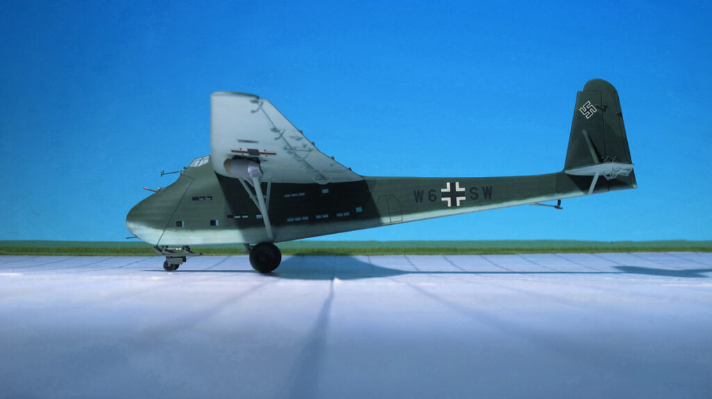
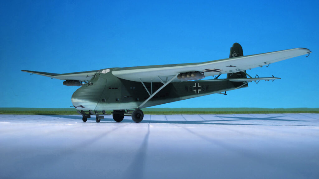
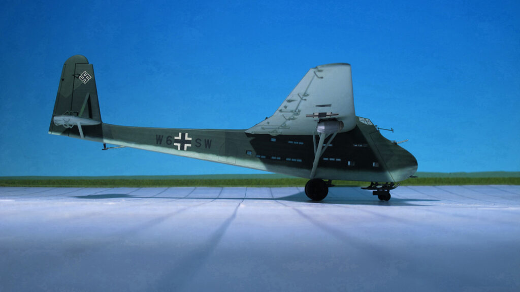
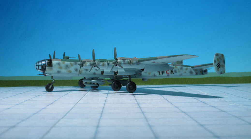
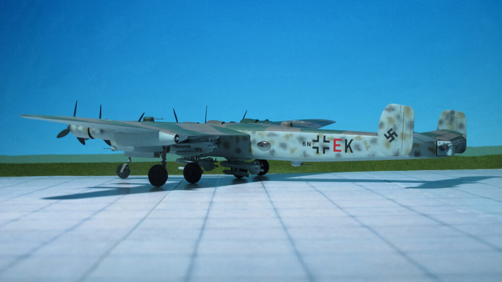
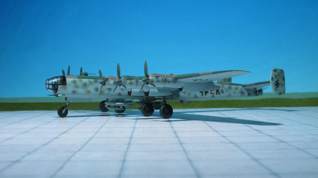
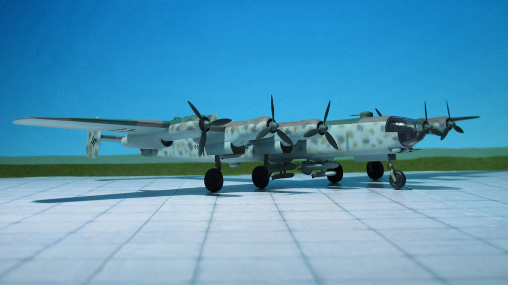
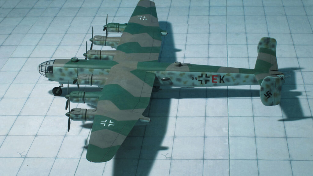
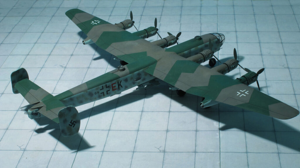
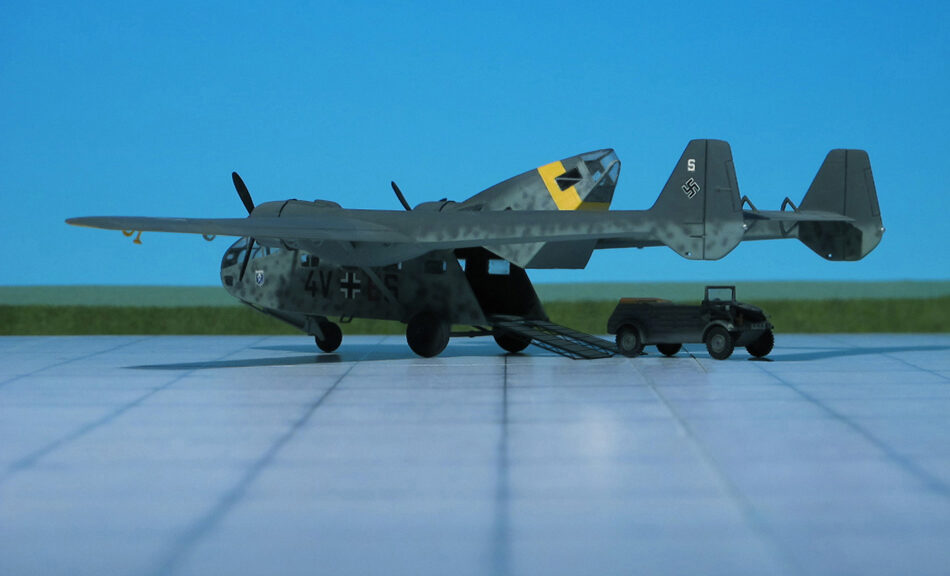
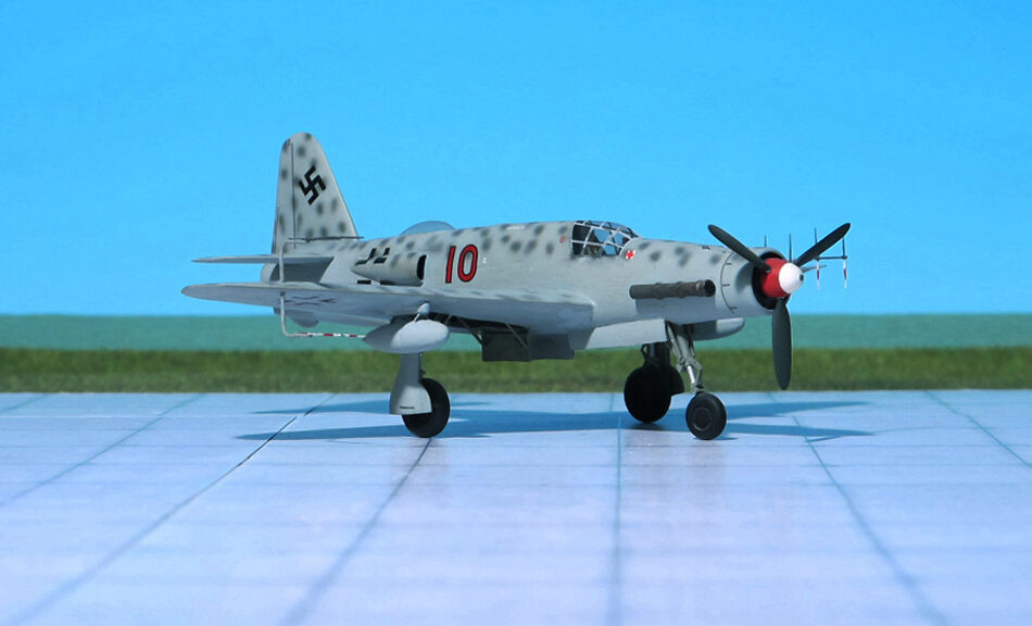
COMMENT: The Messerschmitt Me 323 „Gigant“ (“Giant”) was a German military transport aircraft of World War II. It was a powered variant of the Messerschmitt Me 321 military glider and was the largest land-based transport aircraft to fly during the war. In total, 213 were made, with 15 being converted from the Me 321
The Me 323 was the result of a 1940 German requirement for a large assault glider in preparation for Operation Seelöwe (Operation Sea Lion), the projected invasion of Great Britain. The DFS 230 light glider developed by Deutsches Forschungsinstitut für Segelflug, (German Research Institute for Sailplanes) had already proven its worth in the Battle of Fort Eben-Emael in Belgium, the first ever assault by gliderborne troops, and would later be used successfully in the invasion of Crete in 1941.
However, in order to mount an invasion across the English Channel, the Germans would need to be able to airlift vehicles and other heavy equipment as part of an initial assault wave. Although Operation Sea Lion was cancelled, the requirement for a heavy air transport capability still existed, with the focus shifting to the forthcoming Operation Barbarossa, the invasion of the Soviet Union.
On 18 October 1940, Junkers and Messerschmitt were given just 14 days to submit a proposal for a large transport glider. The emphasis was still very much on the assault role; the ambitious requirement was to be able to carry either an 88 mm gun and its half-track tractor, or a Panzer IV medium tank. The Junkers Ju 322 Mammut (Mammouth) reached prototype form, but was eventually scrapped due to difficulties in procuring the necessary high-grade timber for its all-wood construction, and as was discovered during the Mammut‘s only test flight, an unacceptably high degree of instability inherent in the design. The proposed Messerschmitt aircraft was originally designated Me 261w—partly borrowing the designation of the long-range Messerschmitt Me 261, then changed to Messerschmitt Me 263 later reused for Messerschmitt’s improved rocket fighter design, and eventually became the Me 321. Although the Me 321 saw considerable service on the Eastern Front as a transport, it was never used for its intended role as an assault glider.
Early in 1941, as a result of feedback from Transport Command pilots in Russia, the decision was taken to produce a motorized variant of the Me 321, to be designated Me 323. French Gnome-Rhone GR14N radial engines, rated at 1,164 hp, for take-off as used in the Bloch MB 175 aircraft were chosen for use. This would reduce the burden on Germany’s strained industry.
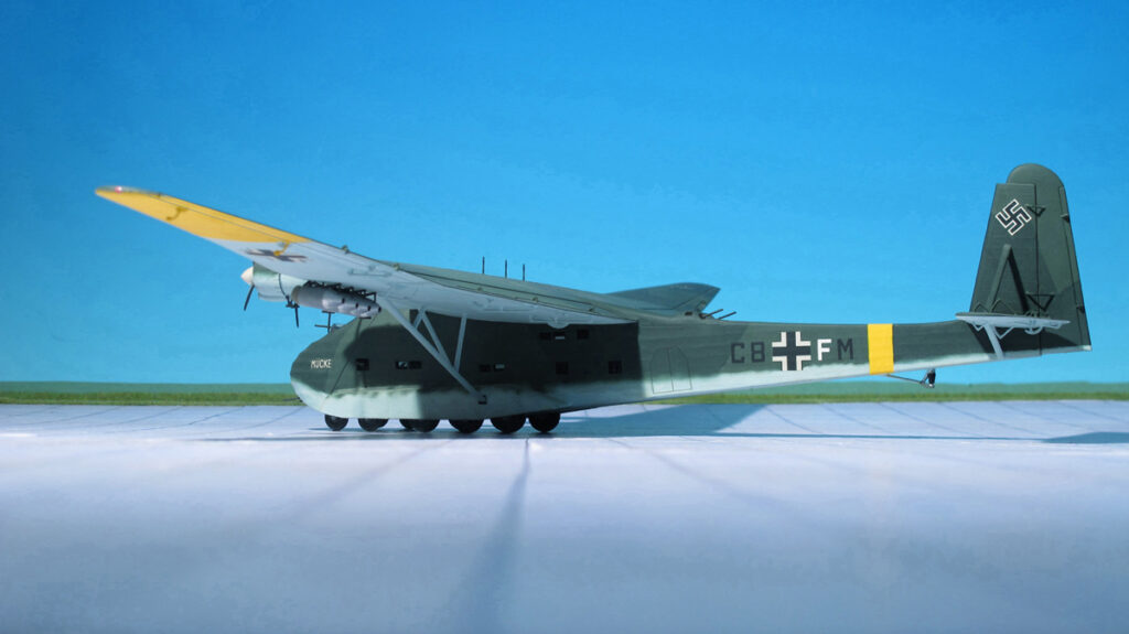
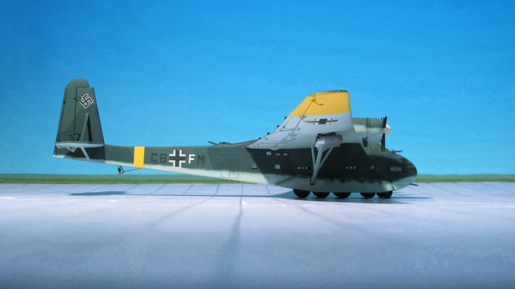
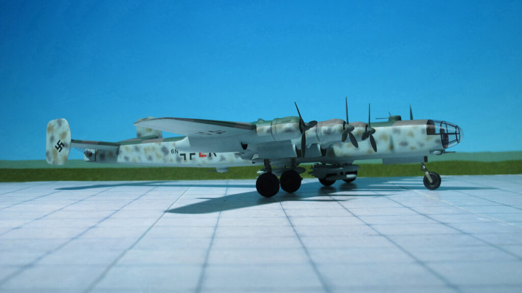
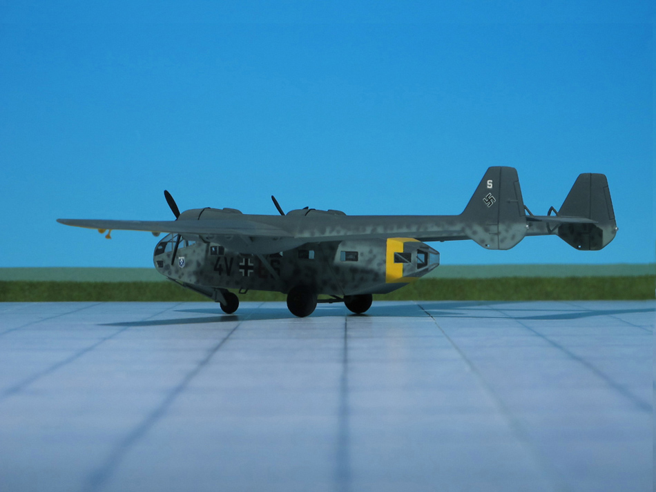
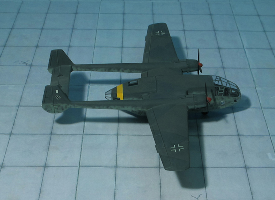
Initial tests were conducted with four Gnome engines attached to a strengthened Me 321 wing, giving modest speed of 130 mph – 50 mph slower than the Junkers Ju 52 transport aircraft. A fixed undercarriage was fitted, with four small wheels in a bogie at the front of the aircraft and six larger wheels in two lines of three at each side of the fuselage, partly covered by an aerodynamic fairing. The rear wheels were fitted with pneumatic brakes that could stop the aircraft within 660 ft.
The four-engined Me 323C was considered a stepping-stone to the six-engined D series. It still required the five-engined Heinkel He 111Z Zwilling (Twin) or the highly dangerous „vic-style“ Troika-Schlepp formation of three Messerschmitt Me 110 heavy fighters and underwing-mounted Walter HWK 109-500 Starthilfe rocket-assist take-off units to get airborne when fully loaded, but it could return to base under its own power when empty. This was little better than the Me 321, so the V2 prototype became the first to have six engines and flew for the first time in early 1942, becoming the prototype for the D-series aircraft.
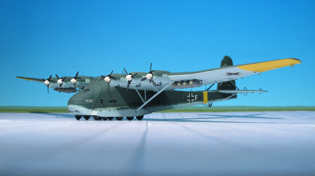
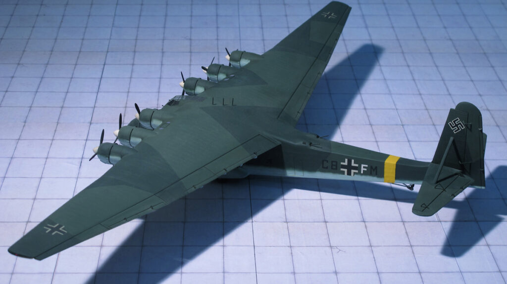
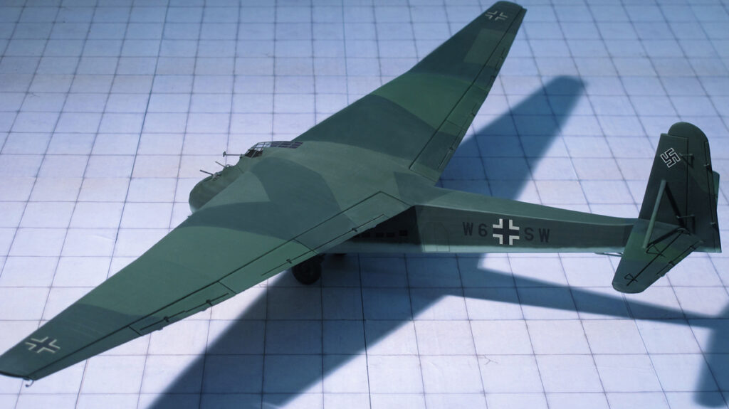
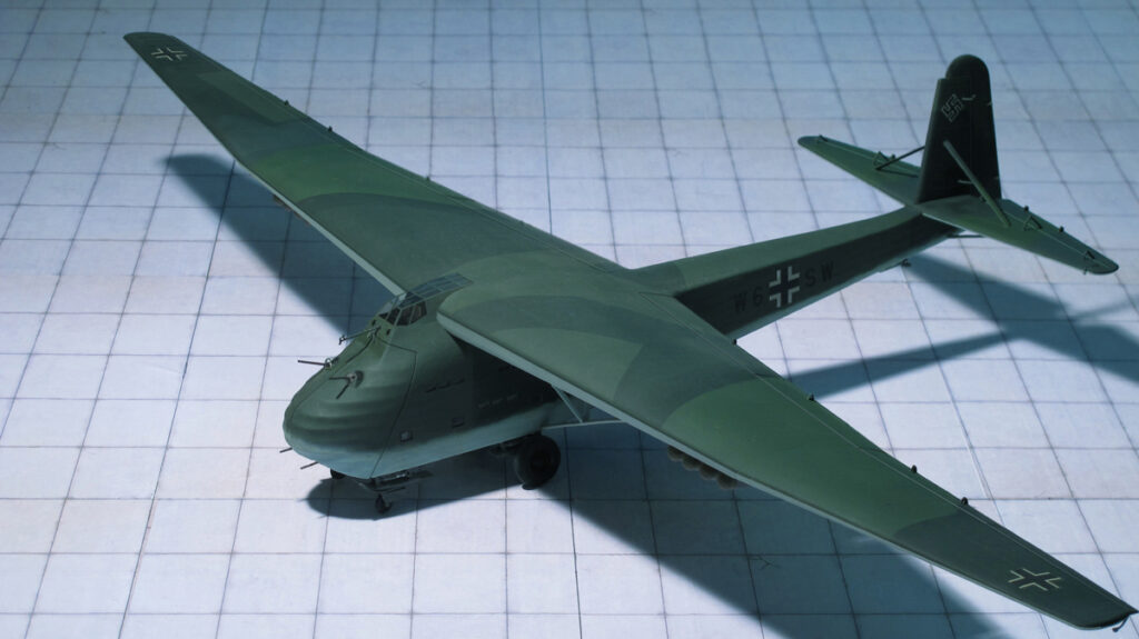
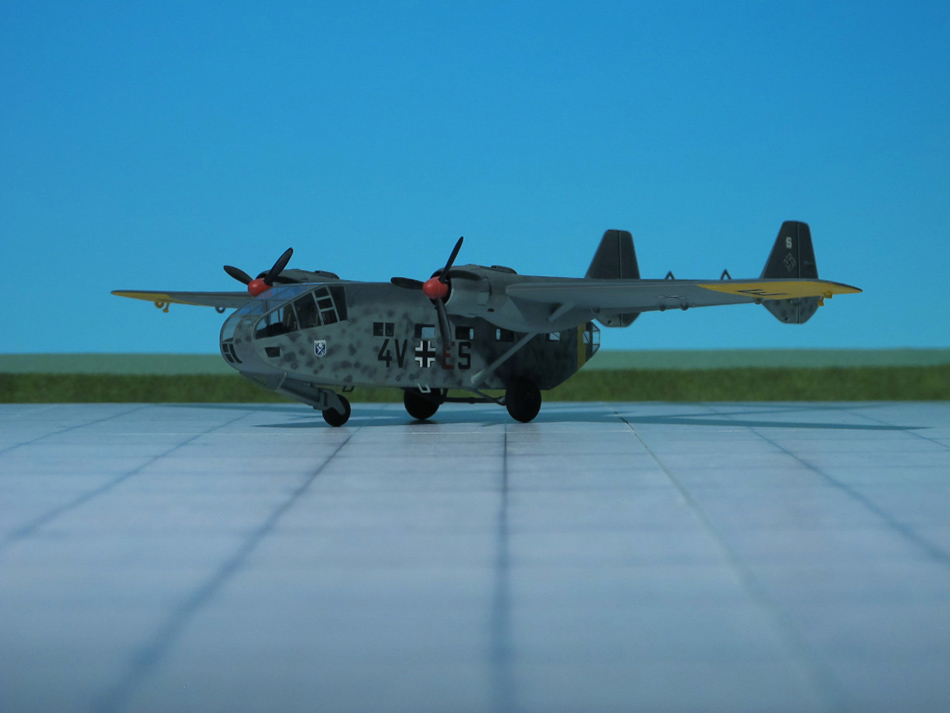
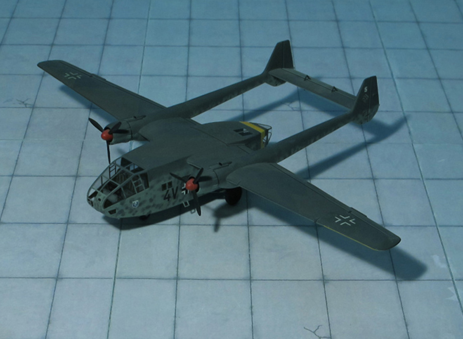
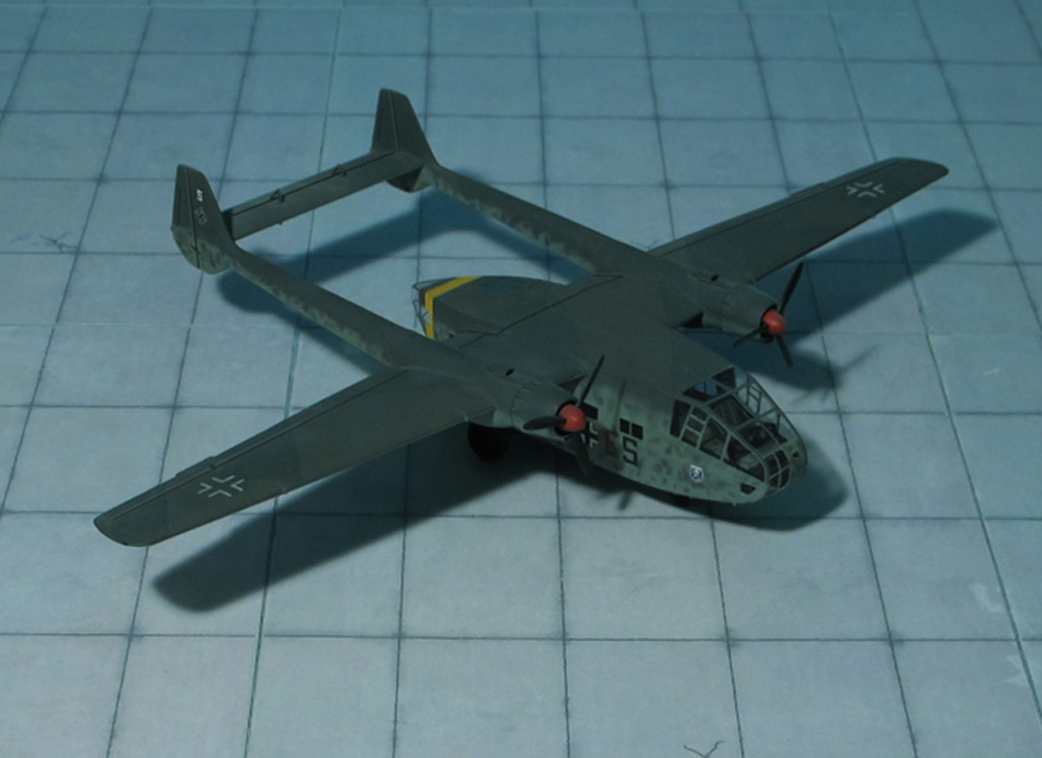
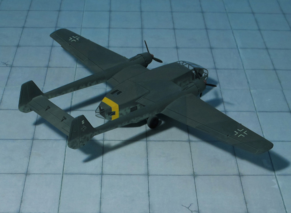
To reduce torque, the aircraft was fitted with three counterclockwise rotation engines on the port wing and three clockwise rotation engines on the starboard wing, as seen looking forward from behind each engine – resulting in the propellers rotating “away” from each other at the tops of their arcs.
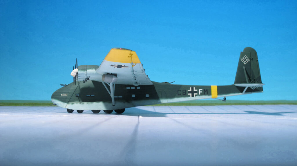
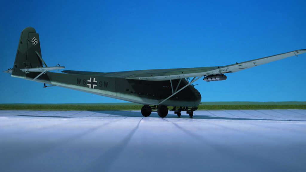
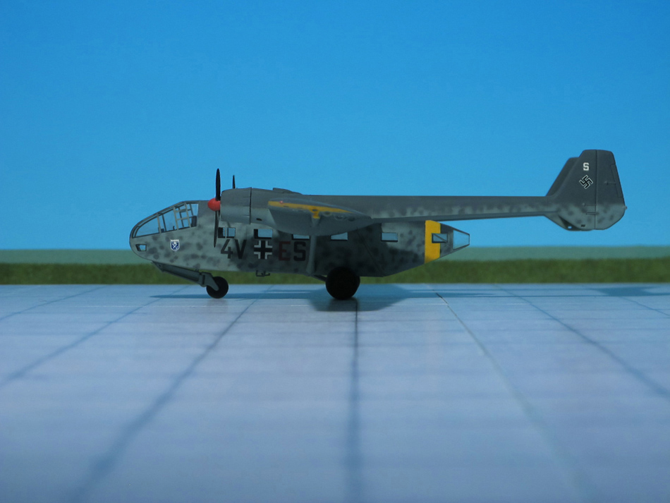
Like the Me 321, the Me 323 had massive, semicantilever, high-mounted wings, which were braced from the fuselage out to the middle of the wing. To reduce weight and save aluminium, much of the wing was made of plywood and fabric, while the fuselage was of metal-tube construction with wooden spars and covered with doped fabric, with heavy bracing in the floor to support the payload.
The “D” series had a crew of five – two pilots, two flöight engineers, and a radio operator. Two gunners could also be carried. The flight engineers occupied two small cabins, one in each wing between the inboard and centre engines. The engineers were intended to monitor engine synchronisation and allow the pilot to fly without worrying about engine status, although the pilot could override the engineers’ decisions on engine and propeller control.
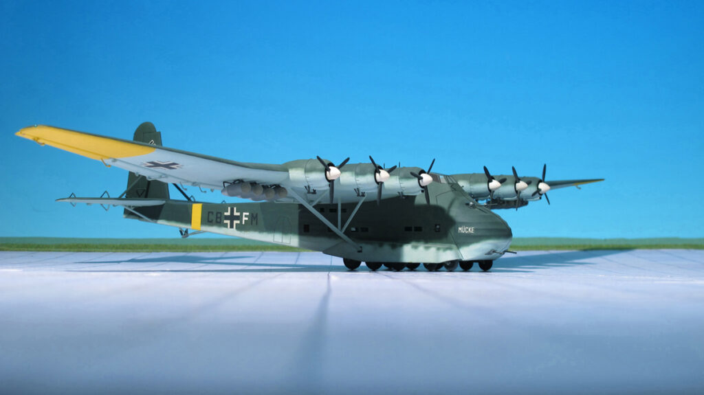
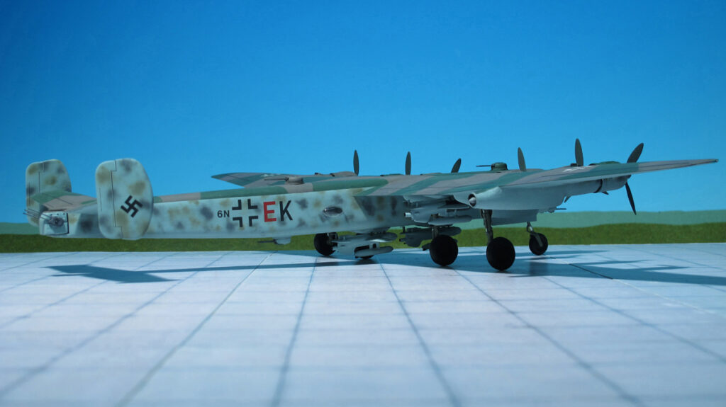
Maximum payload was around 12 tonnes, although at that weight, the Walter HWK 109-500 Starthilfe rocket-assisted take-off units used on the Me 321 were required for take-off. These were mounted beneath the wings outboard of the engines, with the wings having underside fittings to take up to four units. The cargo hold was 36 ft long, 10 f) wide and 11 ft high. Typical loads were one 15 cm sFH 18 heavy field howitzer (5.5 ton) accompanied by its Sd kfz 7 half-track artillery tractor vehicle (11 ton), two 4 ton trucks, 8,700 loaves of bread, an 88 mm Flak gun and accessories, 52 drums of fuel (45 US gal), 130 men, or 60 stretchers.
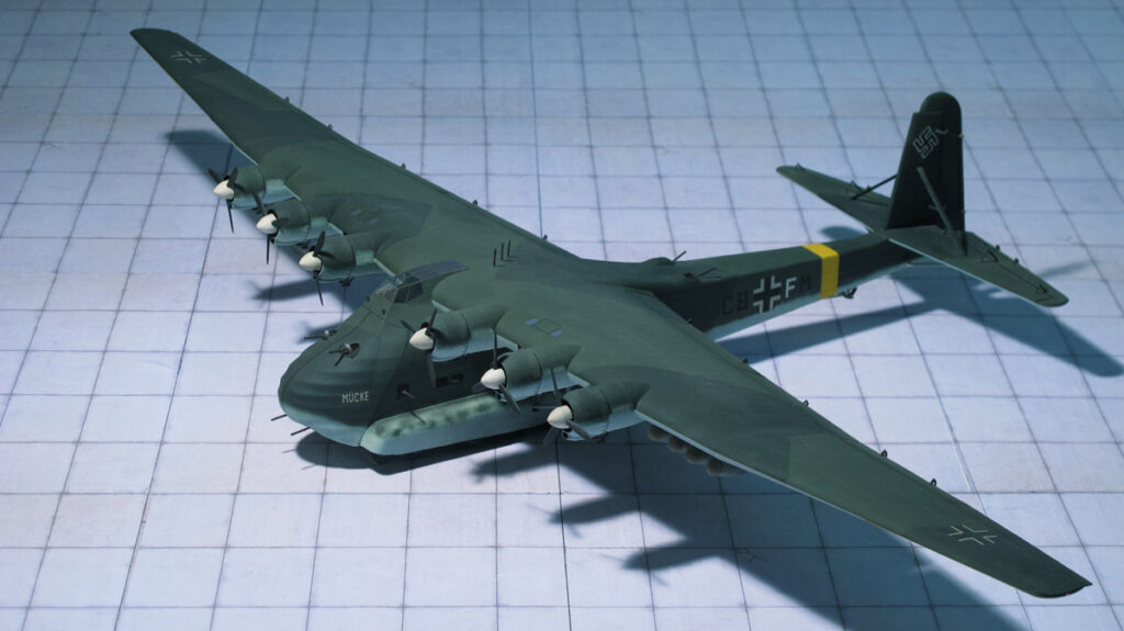
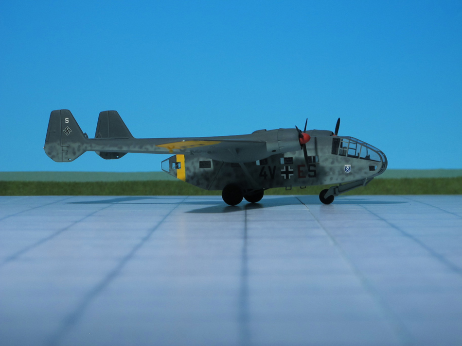
Some Me 321s were converted to Me 323s, but most were built as six-engined aircraft from the beginning. Early models were fitted with wooden, two-blade propellers, while later versions had metal, three-blade, variable-pitch versions.
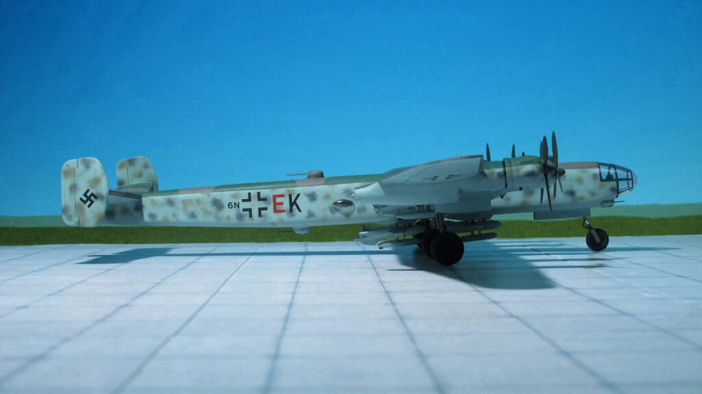
The Me 323 had a maximum speed of only 136 mph at sea level. It was armed with five 13 mm MG 131 machine guns firing from a dorsal position behind the wings and from the fuselage. They were manned by the extra gunners, radio operator, and engineers.
By September 1942, Me 323s were being delivered for use in the Tunisian campaign. They entered service in the Mediterranean theatre in November 1942. High losses among Axis shipping required a huge airlift of equipment across the Mediterranean to keep Rommel’s Afrika Korps supplied.
A total of 198 Me 323s were built before production ceased in April 1944. Several production versions were built, beginning with the Me 323D-1. Later D- and E- versions differed in the choice of power plant and in defensive armament, with improvements in structural strength, total cargo load, and fuel capacity also being implemented. Nonetheless, the Me 323 remained underpowered. A proposal to install six BMW 801 radials did not occur. The Me 323 was also a short-range aircraft, with a typical range (loaded) of 620–750 mi. Despite this, the limited numbers of Me 323s in service were an asset to the Germans, and saw extensive use .
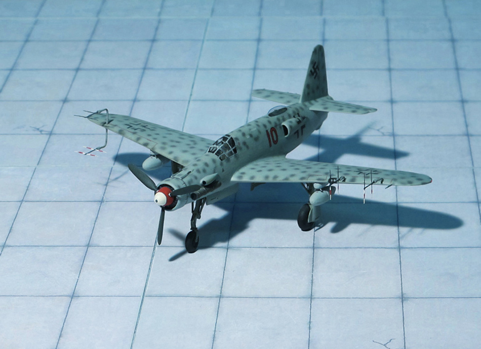
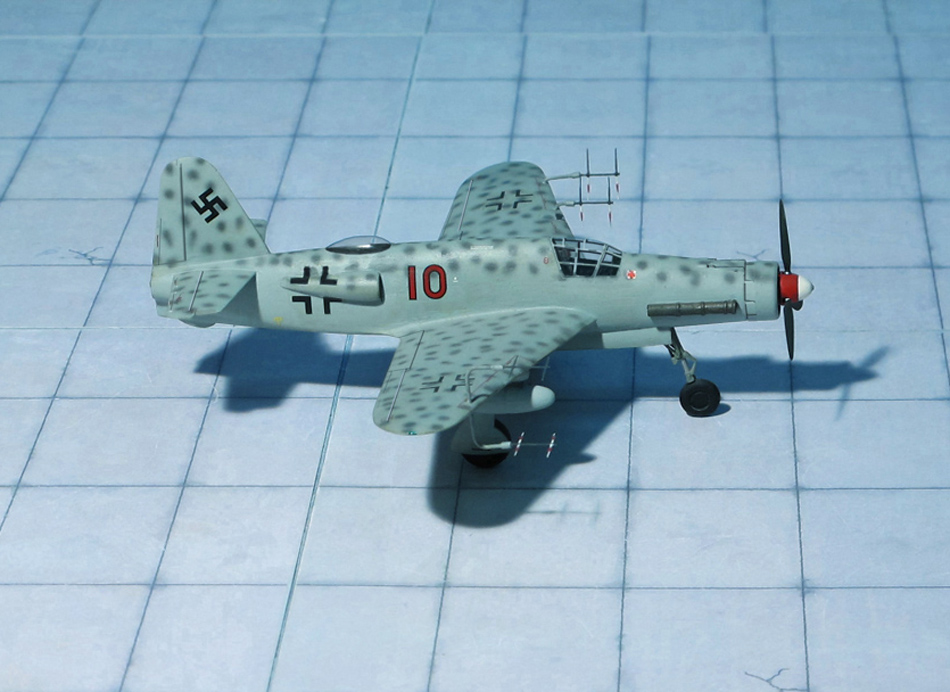
The aircraft shown here belonged to 5./ TG 5 (5th Gruppe/ Transportgeschwader 5, 5th Sqn,/Transport Group 5) (Ref.: 24).