POWER PLANT: Two BMW 801L radial engines, rated at 1,560 hp each
PERFORMANCE: 324 mph in 17.100 ft
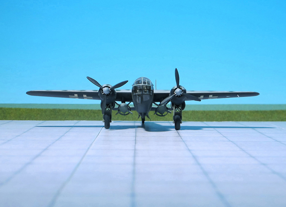
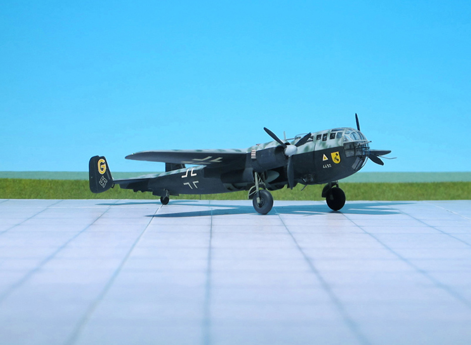
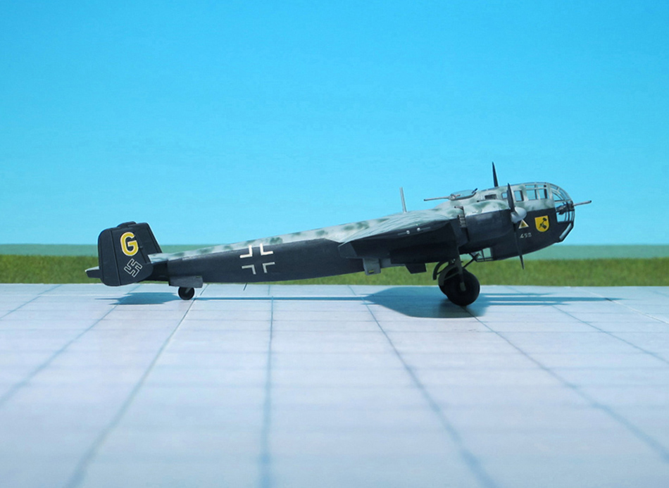
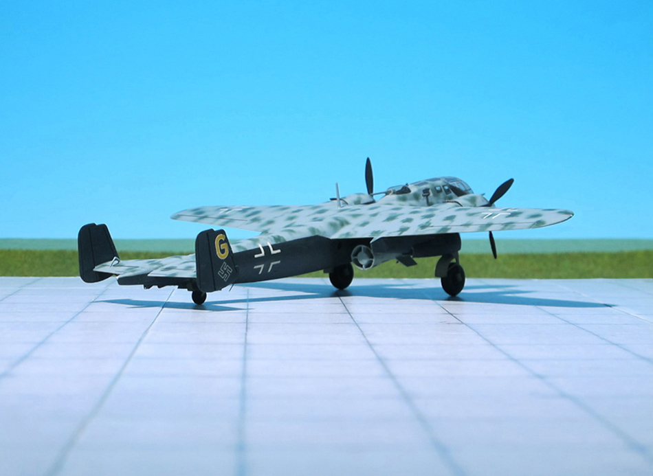
COMMENT: The Dornier Do 217 was a bomber used by the German Luftwaffe during World War II as a more powerful development of the Dornier Do 17, known as the Fliegender Bleistift (German: “flying pencil”). Designed in 1937 and 1938 as a heavy bomber but not meant to be capable of the longer-range missions envisioned for the larger Heinkel He 177 Greif (Griffon), the Do 217’s design was refined during 1939 and production began in late 1940. It entered service in early 1941 and by the beginning of 1942 was available in significant numbers.
The Dornier Do 217 had a much larger bomb load capacity and had much greater range than the Do 17. In later variants, dive bombing and maritime strike capabilities using glide bombs were experimented with considerable success being achieved. Early Do 217 variants were more powerful than the contemporary Heinkel He 111 and Junkers Ju 88, having a greater speed, range and bomb load. The Do 217 served on all fronts in all role as a strategic bomber, torpedo bomber and reconnaissance aircraft. It also performed tactical operations, either direct ground assault or anti-shipping strikes. The Do 217 was also converted to become a night fighter and saw considerable action in the Defence oft he Reich campaign until late in the war.
In 1943, the Do 217 was the first aircraft to deploy precision-guided munition (PGM) in combat, when Ruhrstahl Fritz X radio-guided bombs sank the Italian battleship Roma in the Mediterranean.
To replace the Do 217E, the RLM planned for the He 177A-3 and A-5 to be the long-range carrier aircraft for missiles, owing to the lack of BMW engines to power the Dornier but problems with the engine reliability of the He 177A led to the failure of the plan.
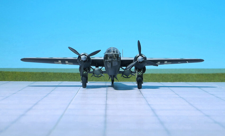
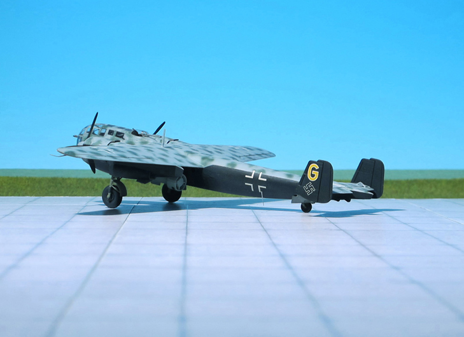
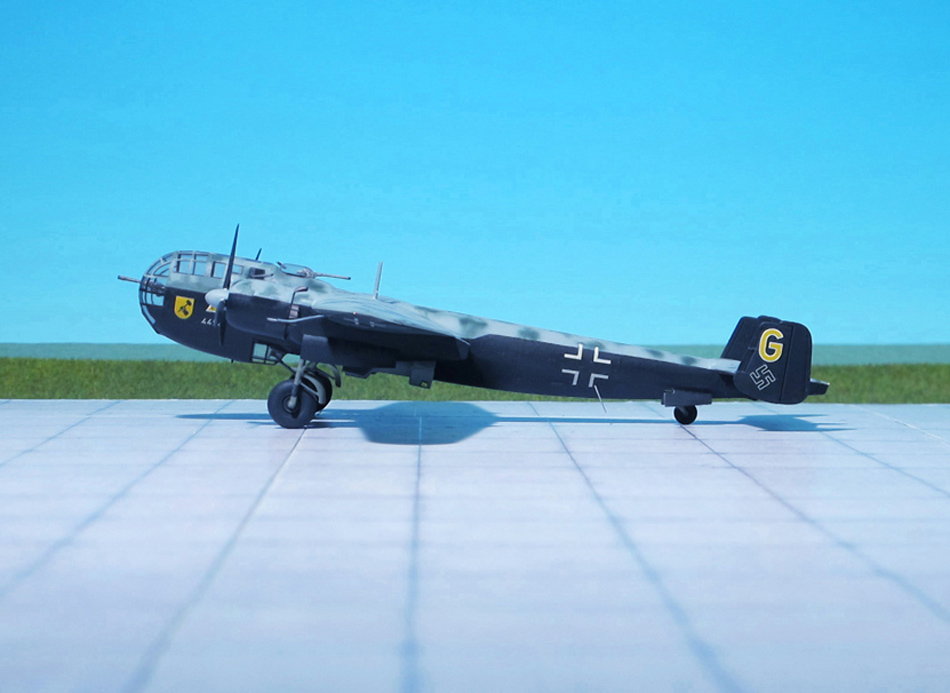
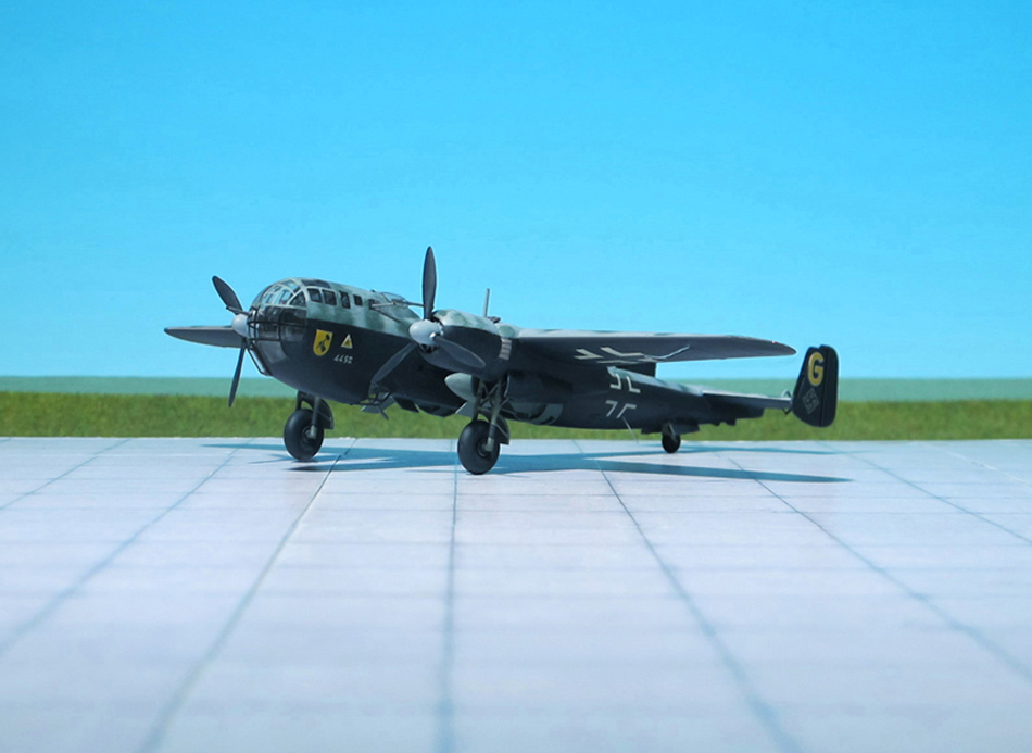
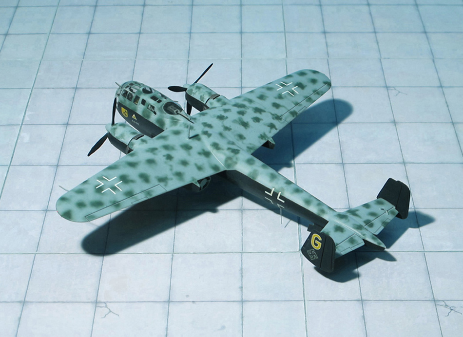
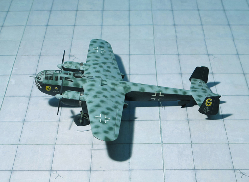
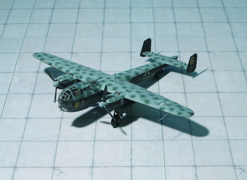
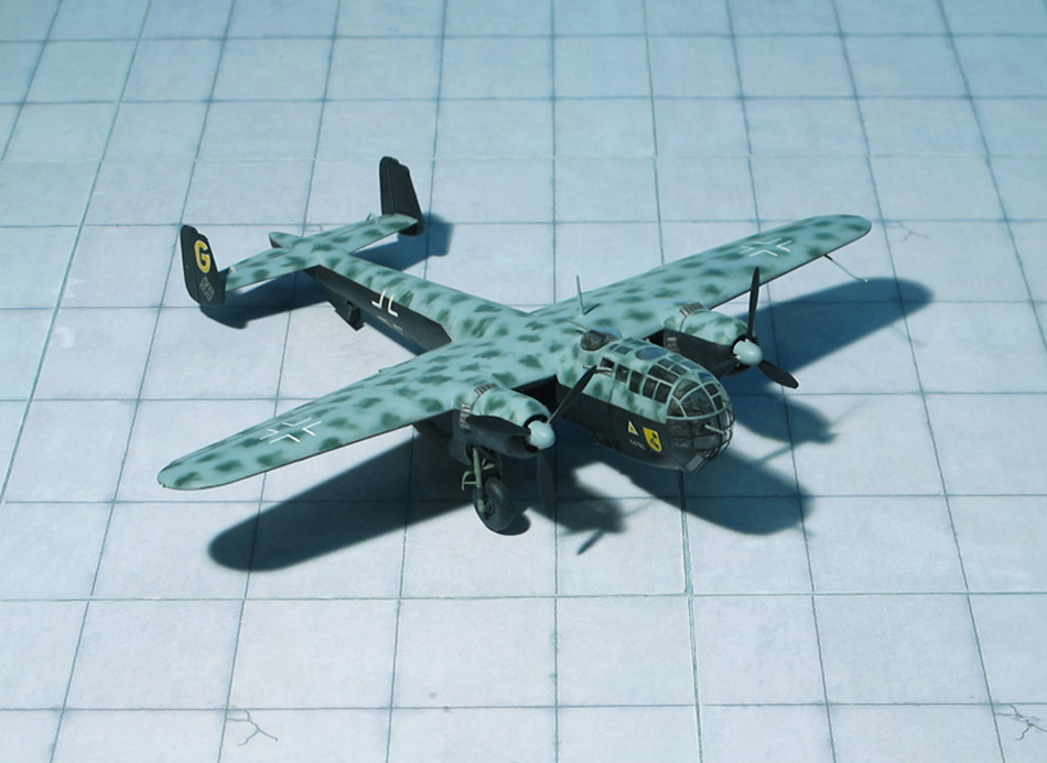
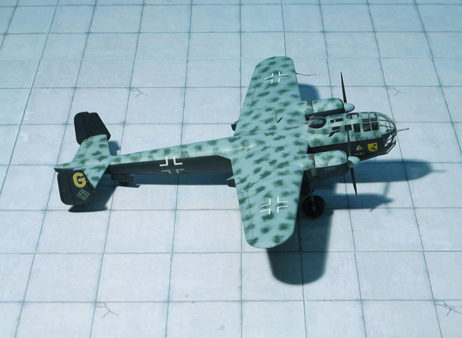
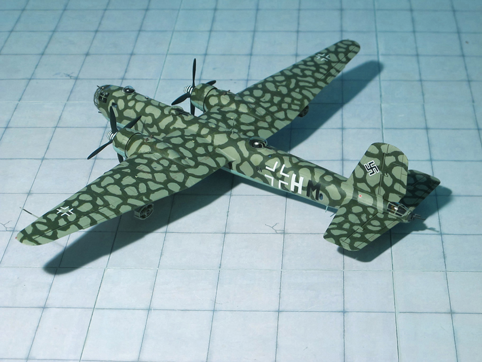
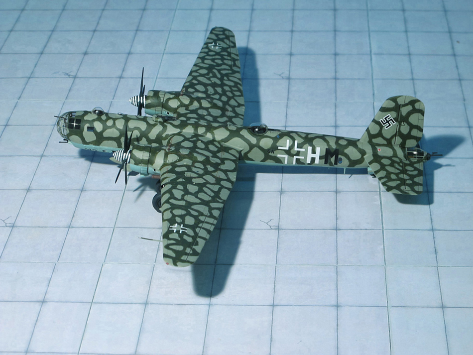
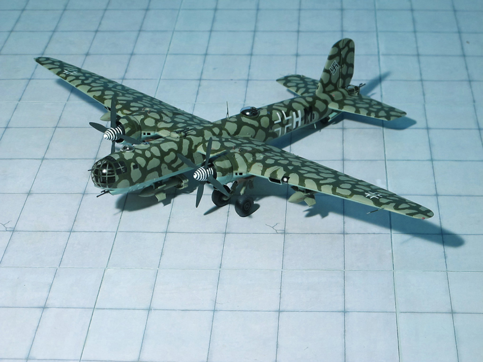
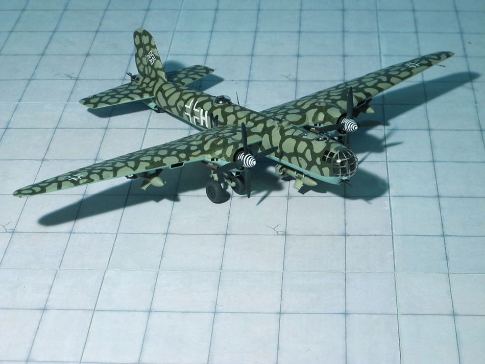
In early 1942, tests on a new and improved, completely glazed cockpit for the Do 217K series had been underway at the Hamburger Schiffbauanstalt (Hamburg Shipbuilding Institute). Do 217E-2s were fitted with a new streamlined “stepless cockpit” following its conceptual debut in January 1938 for the Heinkel He 111P, as this design philosophy became the standard for almost all German bombers later in World War II, which eliminated the separate windscreen panels for the pilot of earlier versions of the Do 217. The lower nose of the Do 217K-version also retained the Bola (Bodenlafette, ventral gun mounting) inverted-casemate gondola for a rearwards-aimed ventral defensive armament emplacement, with its forward end fully incorporated with the new nose glazing design. The cabin design passed the tests easily. Initial flights took place on March 1942 after teething problems had been resolved. The Do 217K V1 flew with BMW 801A-1s from Erpobungsstelle Rechlin. This was followed by the ten-airframe pre-production batch, Do 217K-01 to K-010. BMW believed that the type could reach an operational ceiling of 25.000 ft, notwithstanding an A.U.W of 16.8 t. Tests at Peenemünde in June and July 1943 showed that while the Do 217K could carry and deploy a Ruhrstahl Fritz-X precision guided munition, it was still controllable.
The Do 217K-1 was a bomber version and was powered by two BMW 801L engines with GM 1 nitrous oxide boost. This increased the Do 217K-1s maximum speed by 53 mph at 26.250ft at a rate of 100 g/s. With 50 g/s the aircraft’s operational ceiling could be extended from 27.560 ft to 32.152ft.
In total 220 Do 217K-1 were built followed by Do 217K-2 with extended wings (Ref.:24)
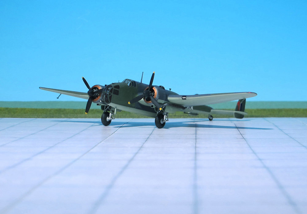
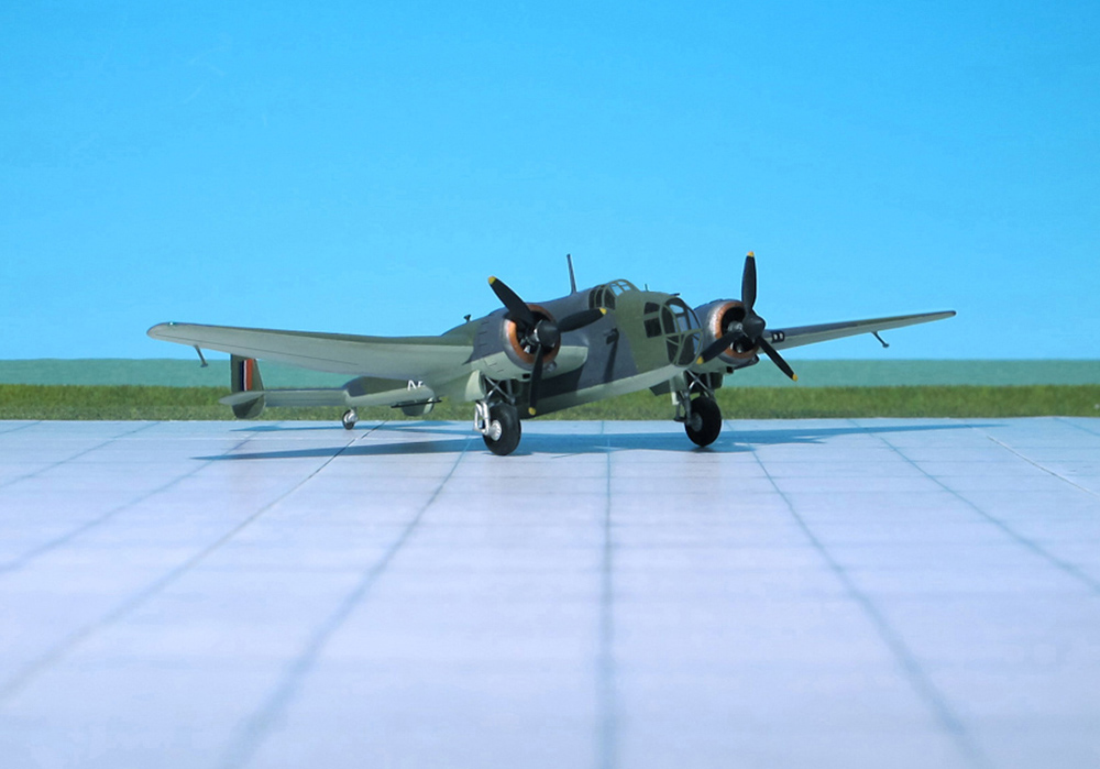
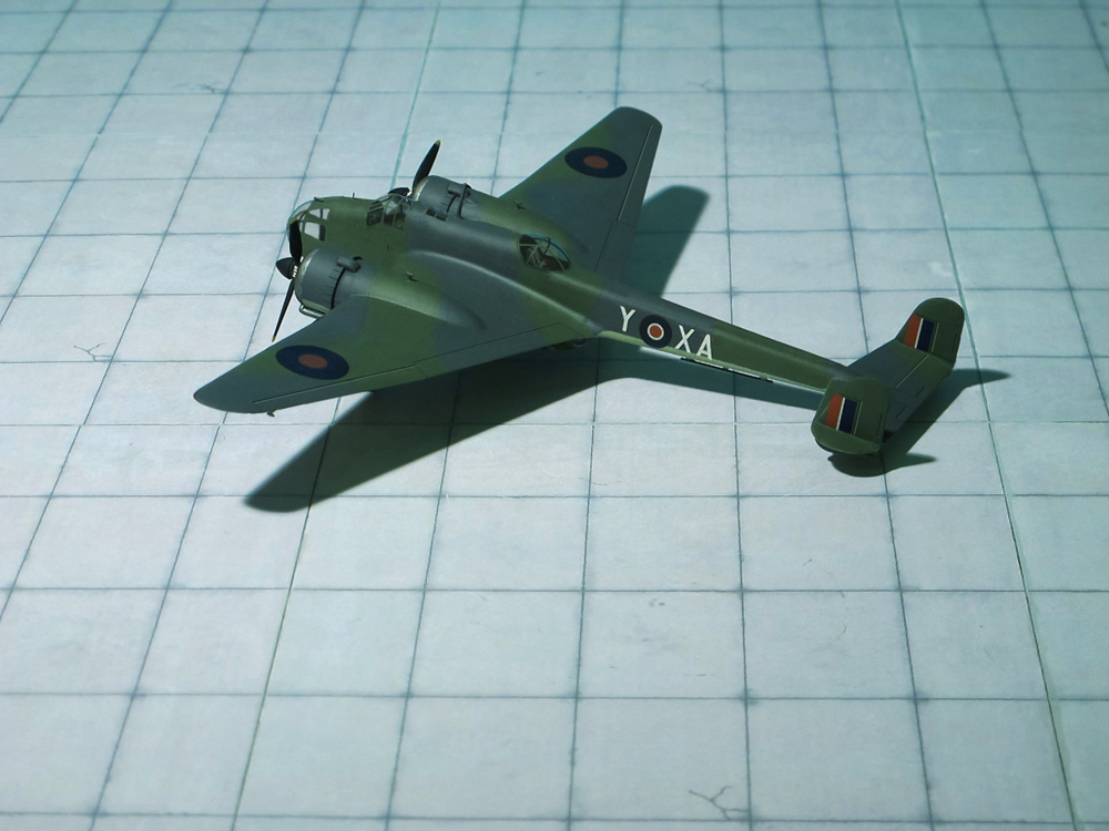
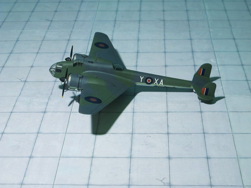
POWER PLANT: Two Bristol “Pegasus” XVIII radial engines, rated at 1000 hp each
PERFORMANCE: 247 mph at 13,000 ft
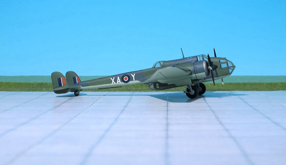
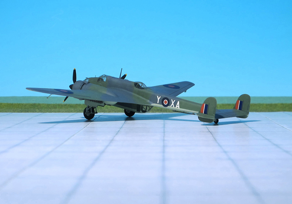
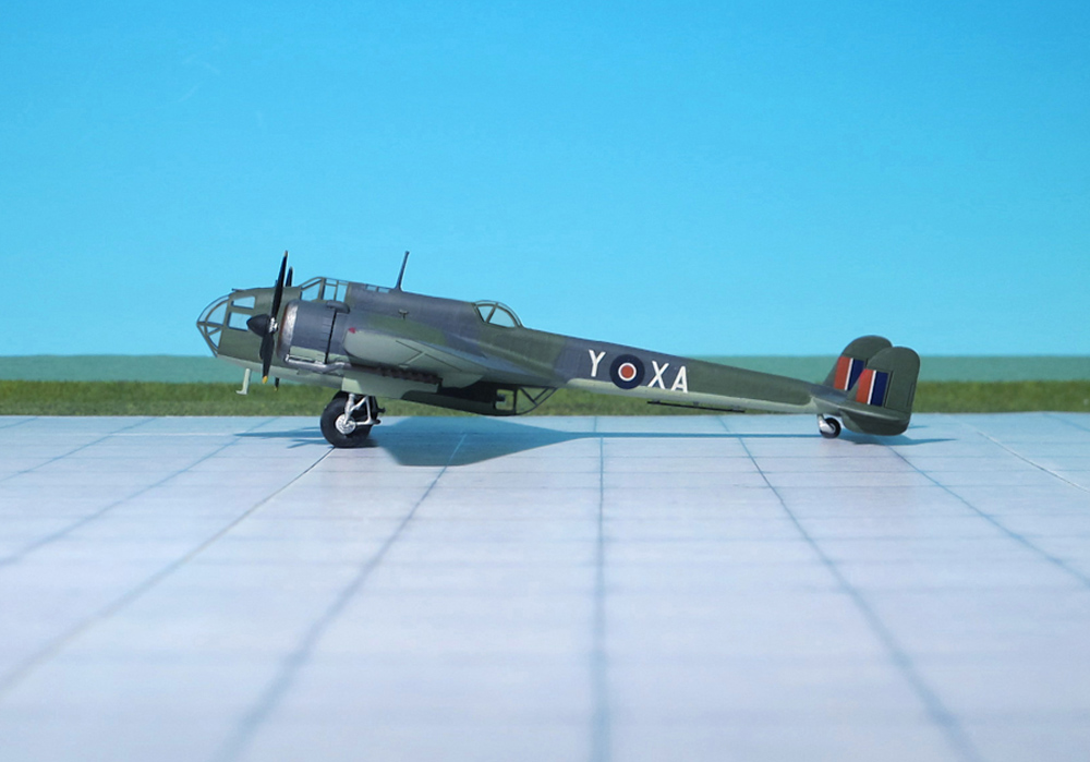
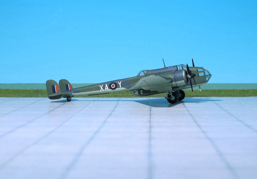
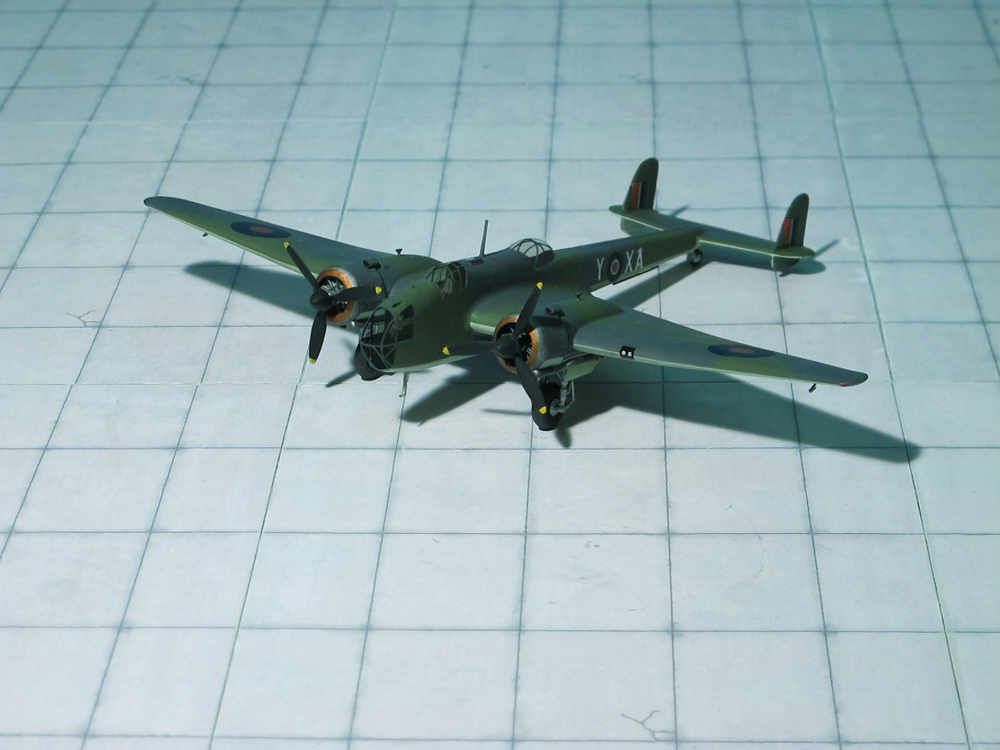
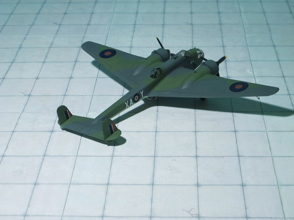
COMMENT: The Handley Page HP.52 Hampden was a British twin-engine medium bomber of the Royal Air Force (RAF). It was part of the trio of large twin-engine bombers procured for the RAF, joining the Armstrong Whitworth Whitley and Vickers Wellington. The newest of the three medium bombers, the Hampden was often referred to by aircrews as the “Flying Suitcase” because of its cramped crew conditions. The Hampden was powered by Bristol Pegasus radial engines but a variant known as the Handley Page Hereford had in-line Napier Daggers.
The Hampden served in the early stages of the Second World War, bearing the brunt of the early bombing war over Europe, taking part in the first night raid on Berlin and the first 1.000 bomber raid on Cologne. When it became obsolete, after a period of mainly operating at night, it was retired from RAF Bomber Command service in late 1942. By 1943, the rest of the trio were being superseded by the larger four-engined heavy bombers such as the Avro Lancaster and Handley Page Halifax.
The Hampden Mk I had a pilot, navigator/bomb aimer, radio operator and rear gunner. Conceived as a fast, manoeuvrable “fighting bomber”, the Hampden had a fixed forward-firing Browning machine gun in the upper part of the fuselage nose. To avoid the weight penalties of powered turrets, the Hampden had a curved Perplex nose fitted with a manual Vickers K machine gun and a Vickers K installation in the rear upper and lower positions. The layout was similar to the all-guns-forward cockpits introduced about the same time in Luftwaffe medium bombers, notably the Dornier Do 17.
The Hampden had a flush-rivette stressed skin, reinforced with a mixture of bent and extruded sections in an all-metal monocoque design. A split-assembly construction technique was employed: sections were prefabricated and then joined, to enable rapid and economic manufacture. The fuselage was in three big sections – front, centre and rear – that were built using jigs The centre and rear sections were made of two halves, which meant that the sections could be fitted out in part under better working conditions prior to assembly. All possible assembly work was performed at the benches prior to installation upon each aircraft.
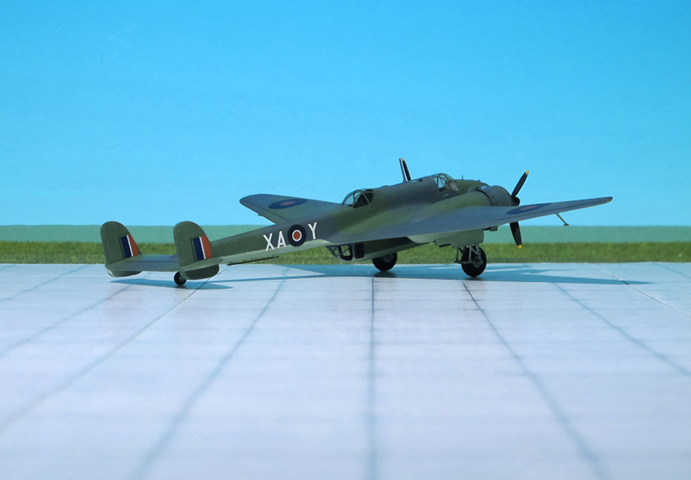
The wings were made up of three large units: centre section, port outer wing and starboard outer wing, which were also subdivided. Each section was built around a main girder spar, leading edge section and trailing edge section. The wing made use of wingtip slots and hydraulically-actuated trailing edge flaps; the flaps and ailerons had stress-bearing D-spars. The configuration of the wing was a key feature of Hampden, being highly tapered and designed to exert low levels of drag; these attributes were responsible for the aircraft’s high top speed for the era of 265 mph while retaining a reasonably low landing speed of 73 mph.
The Hampden’s flying qualities were typically described as being favourable; It was extraordinarily mobile on the controls. Pilots were provided with a high level of external visibility, assisting the execution of steep turns and other manoeuvres. The control layout required some familiarization, as some elements such as the hydraulic controls were unassuming and unintuitive. Upon introduction, the Hampden exhibited greater speeds and initial climb rates than any of its contemporaries while still retaining favourable handling qualities.
The slim and compact fuselage of the aircraft was quite cramped, wide enough only for a single person. The navigator sat behind the pilot and access in the cockpit required folding down the seats. Once in place, the crew had almost no room to move and were typically uncomfortable during long missions. Aircrews referred to the Hampden by various nicknames due to this, such as Flying Suitcase, Panhandle, and Flying Tadpole.
The last Bomber Command sorties by Hampdens were flown on the night of 14/15 September 1942 by 408 Squadron, RCAF against Wilhelmshaven. After being withdrawn from Bomber Command in 1942, it operated with RAF Coastal Command through 1943 as a long-range torpedo bomber. These Hampden TB Mk I had a Mk XII torpedo in an open bomb bay and a 230 kg bomb under each wing. Furthermore, the Hampdens were in action as maritime reconnaissance aircraft. Between 1936 to1941 a total of 1,430 Hampdens were built; 500 by Handley Page, 770 by English Electric, and 160 by Canadian Associated Aircraft (Ref.: 24).
POWER PLANT: Four Daimler-Benz DB 603E liquid-cooled engines, rated at 1,777 hp each
PERFORMANCE: 447 mph
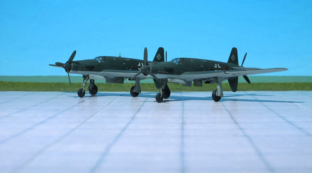
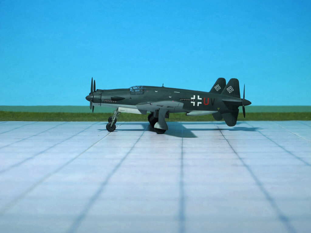
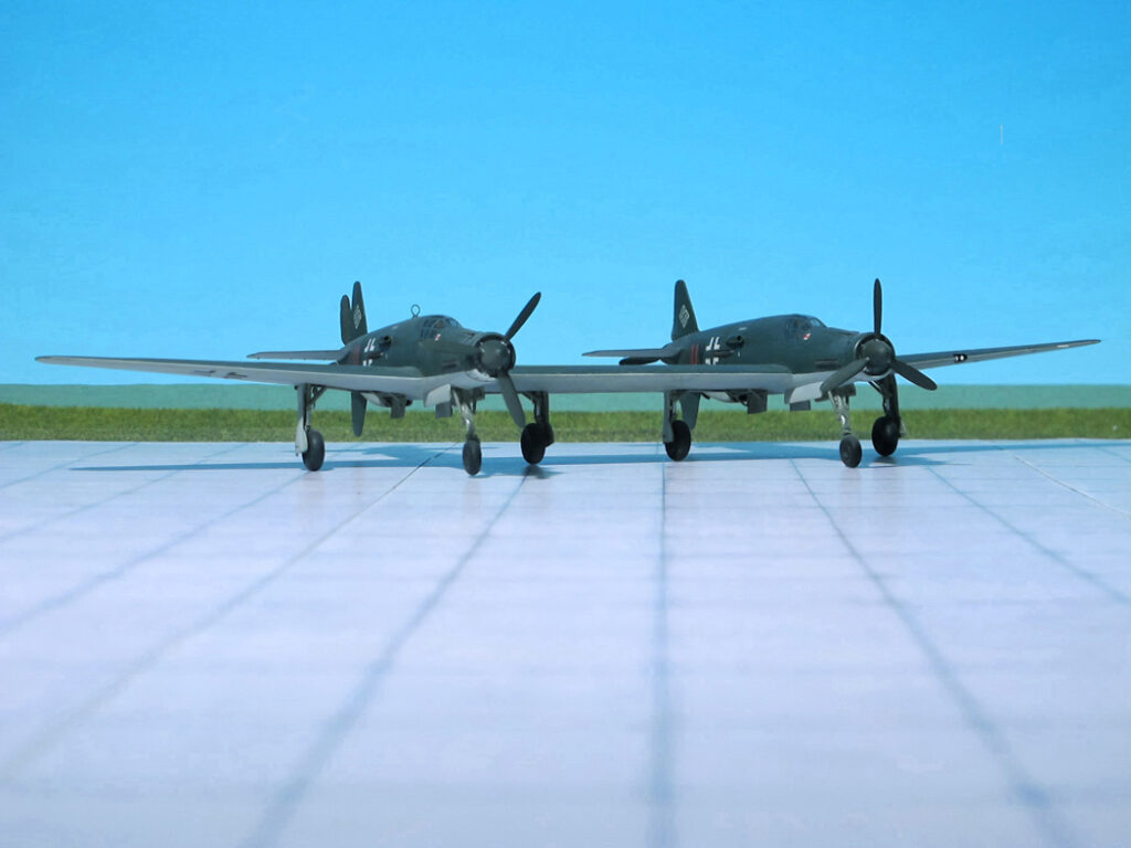
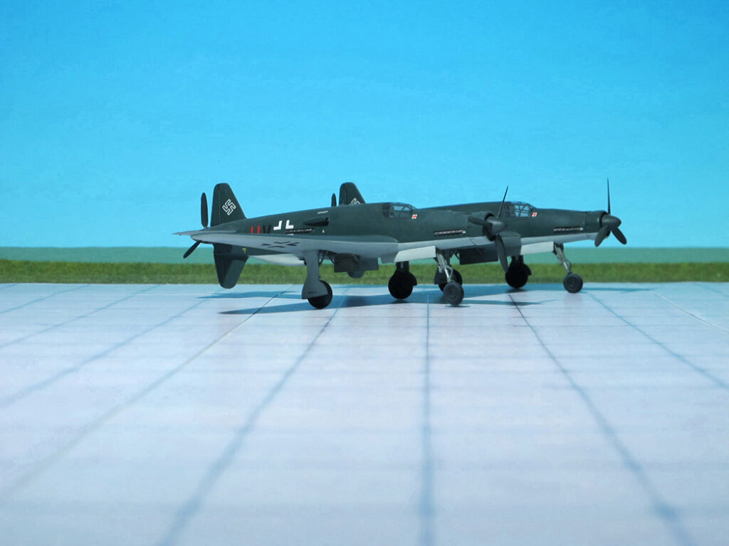
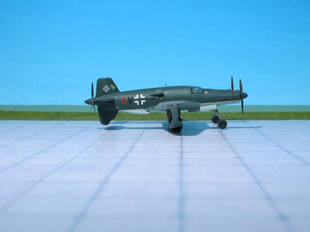
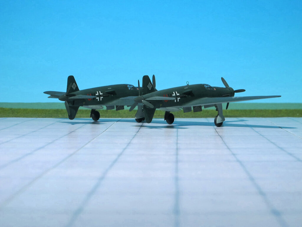
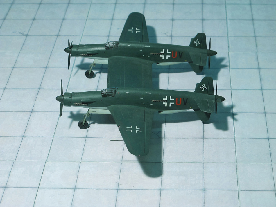
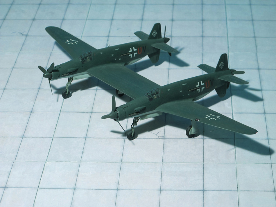
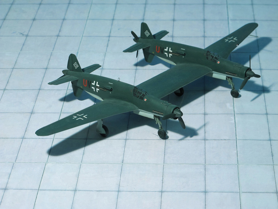
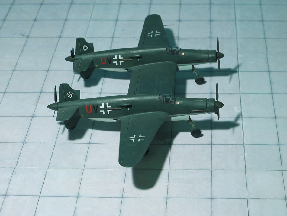
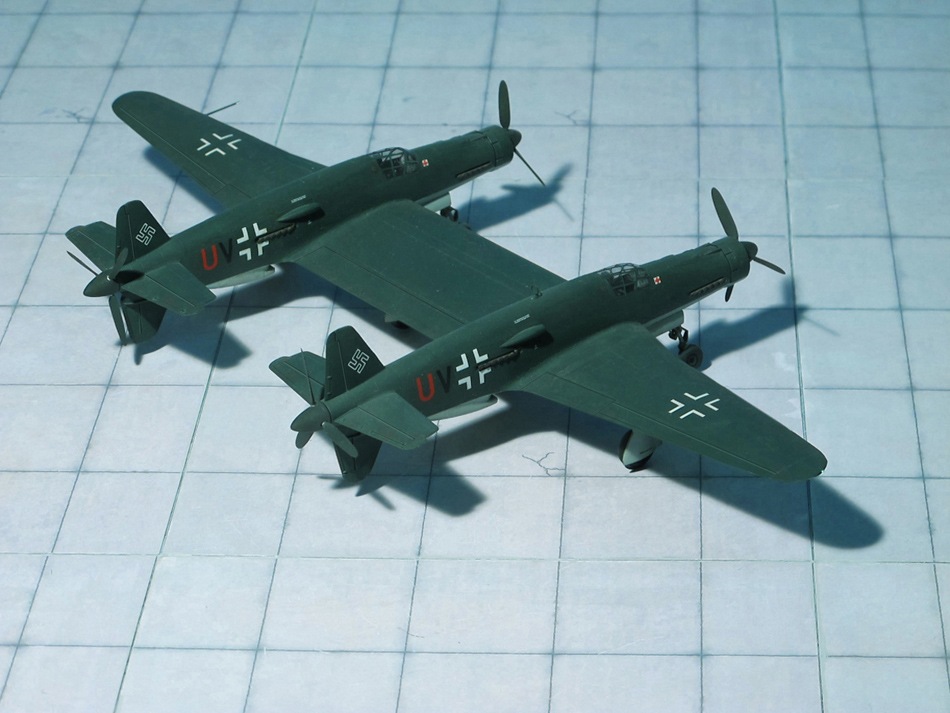
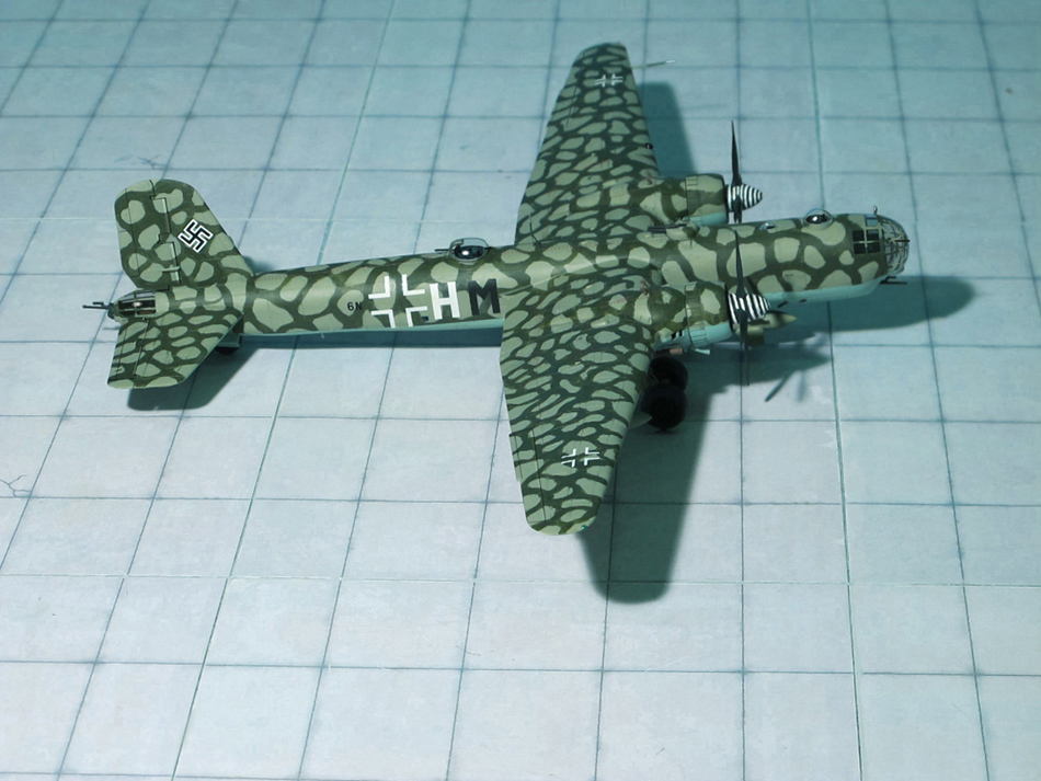
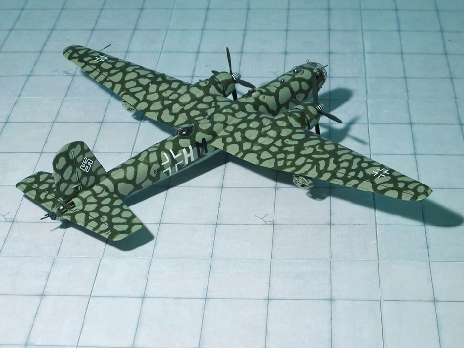
COMMENT: The Dornier Do 635 was a WW II long-range reconnaissance aircraft of the German Luftwaffe proposed by Dornier Company, as two Dornier Do 335 fuselages joined by a common center wing section.
In 1944, designers of Dornier Flugzeugwerke proposed the RLM a long-range reconnaissance aircraft with a range of 2.480 mi under the designation Dornier Do 335Z (Z for Zwilling ; “Twin”). Similar to the Heinkel He 111Z, a combination of two Heinkel He 111 bombers joined by a common center wing section, two Dornier Do 335B fuselages were connected by a center wing section. The pilot was seated in the left fuselage, the radio operator/navigator sitting in the right fuselage. Armament was not envisaged. The RLM confirmed the design provided the range was increased to app. 3.720 mi. Further modifications changed the design from the original Do 335 into a completely new aircraft; the new RLM designation was now Dornier Do 635. Four prototypes were ordered and begin of production was planned for June 1945.
On order of the RLM and representatives of the Luftwaffe the cooperation with Dornier was cancelled and all further development was transferred to Heinkel Flugzeugwerke.
Reason might be that Heinkel’s team had much experience with the Heinkel He 111Z and its twin fuselage combination. The designation of the project was internally changed to Heinkel He P.1070, officially Heinkel He 535 (or He 635, depending on literature). Again, profound changes were required. In order to increase range three external fuel tanks under the outer and center wings were provided, the wing span was reduced and the fuselage length was increased.
All these changes did not satisfy the RLM, so the design was revised again. The crew compartment was now solely positioned in the left fuselage and enlarged to seat three crew members: pilot, copilot and observer/navigator. Wing span was increased again, the center wing section was shortened to bring both fuselages closer together and the inner tail planes were provided as a common sector.
Meanwhile, a lot of time was wasted due to permanent changes in the requirements of the design. Finally, all further development was transferred to Junkers Flugzeugwerke. Prof. Hertel and his team refined the design once again, now under the designation Junkers Ju 635. The aim was to simplify the aircraft for easier production and an increase of range to app. 7.200 mi.
As its predecessor the Junkers design used two modified Dornier Do 335 fuselages, joined by a center wing section of constant chord, the outer wing panels were tapered back. Four Daimler-Benz DB 603E-1 engines supplied the power, one in each forward fuselage pulling and two in each rear fuselage driving a pusher propeller via a long drive shaft. Fuel was carried in ten internal wing tanks, four in the fuselages and possibly one in each fuselage bay. The port fuselage bay carried two Rb 50/30 cameras and the starboard bay contained five 60 kg marker bombs. A crew of three was envisioned, although this could be increased to four eventually. The pilot and the radio operator sat in the port fuselage and a second pilot sat in the starboard fuselage. The fourth crew member (navigator) was also to sit in the starboard fuselage. The landing gear was to consist of two nose wheels under each fuselage nose, two main wheels which were fitted with mud guards to protect the rear radiator intakes, and a jettisonable fifth wheel located beneath the center wing, which was fitted with a parachute for recovery. The main wheels were modified from the Junkers Ju 352 transports wheels. Two Walter HWK 109-500 RATO (Rocket Assisted Take Off) units could be fitted to assist take off. No armament was included due to the fact that this was a long-range reconnaissance aircraft and thus all weight was reserved for fuel and speed.
Four prototypes and six preproduction aircraft were orderd, the first example planned to take-off on February 1945. By early 1945, wind-tunnel models had been tested and cockpit mockups had been constructed. But by February 1945 due to the worsening war situation all further work on the Junkers Ju 635 was stopped.
The model shown here is the first design of the Dornier Do 635 (Ref.: 17, 24).
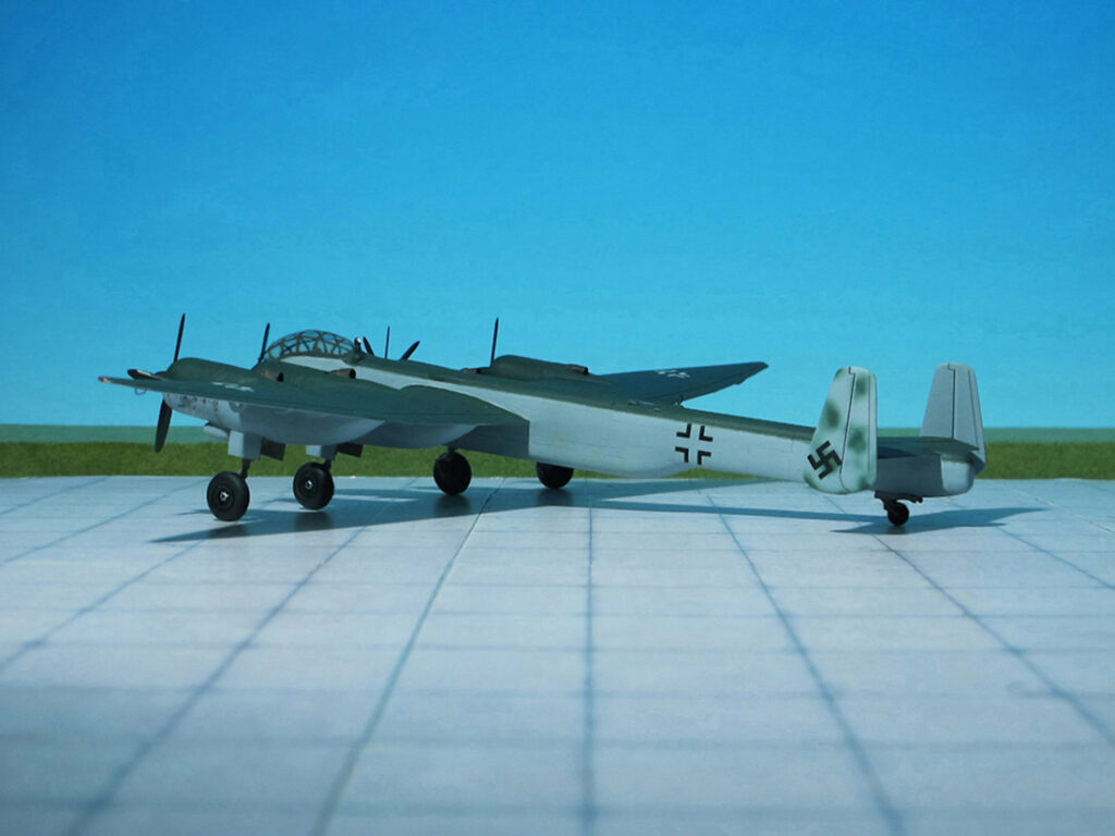
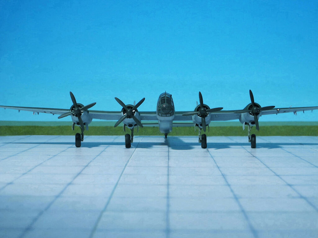
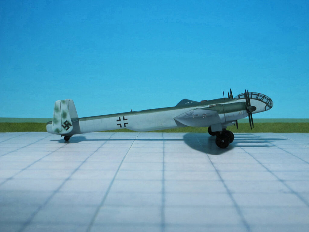
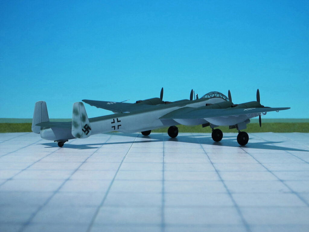
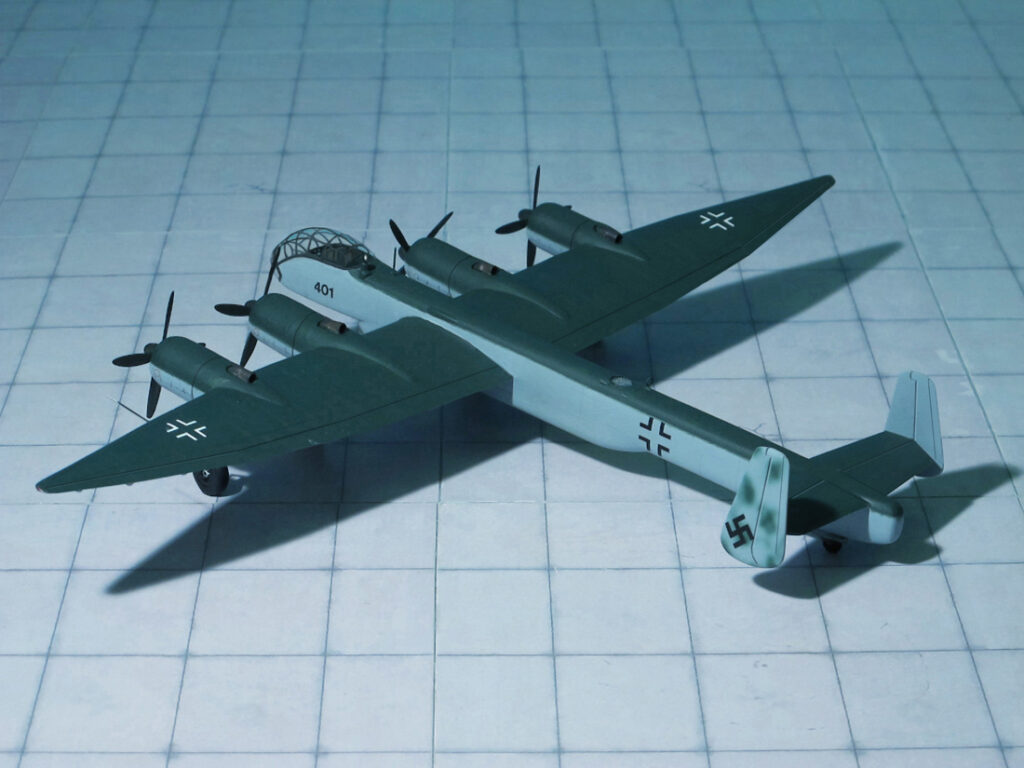
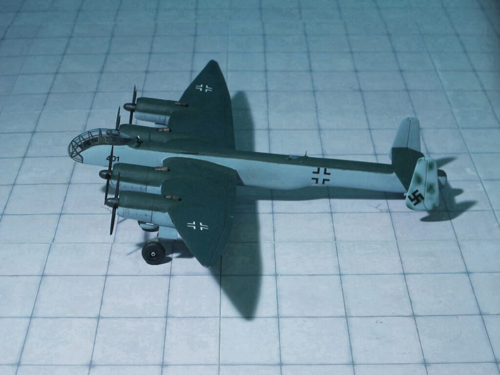
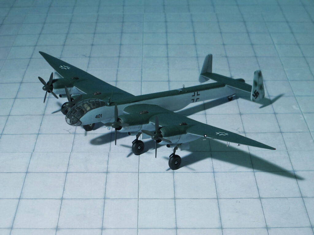
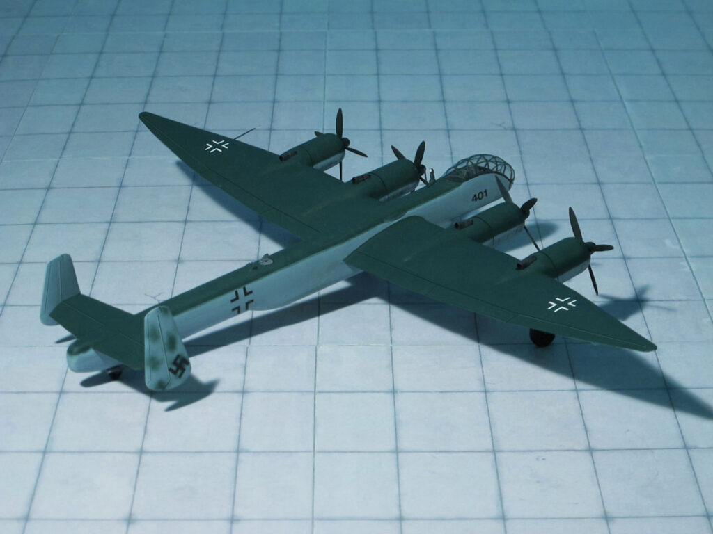
POWER PLANT: Four BMW 801TJ or BMW 802 radial engines, rated at 2,500 hp each
PERFORMANCE: 429 mph at 23,620 ft
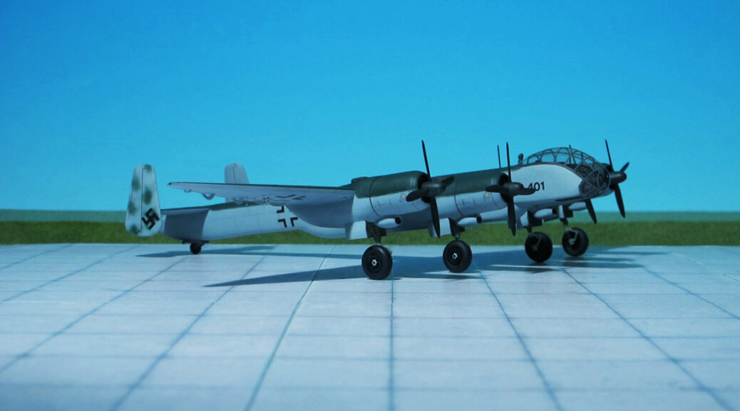
COMMENT: The Junkers Ju 488 was Germany’s last real attempt to create a four-engined, long range bomber. In early 1944, Junkers design department at Dessau made a proposal to simply and quickly produce a heavy bomber, using a minimum of new building jigs or parts. Basically, the Ju 488 was to be constructed out of existing Junkers aircraft. The Ju 388K was to supply the pressurized crew cabin, the Ju 188E supplied the rear fuselage, the ventral pannier was to come from the Ju 88A-15 and Ju 388K series, outer wing sections from the Ju 388K and finally the entire twin fin tail section from the Ju 288C. Added to this collection were a new center fuselage section and a parallel wing center section, to carry the four engines.
The Ju 488 V401 and V402 were to be entirely of metal construction, with the exception of the ventral pannier, which was constructed of wood. The fuselage had an internal bomb bay and five fuel tanks located behind the fuselage and above the bomb bay. The mid-fuselage mounted wing was tapered on the outer wing panels and featured a two spar, all metal construction, with a total of eight fuel tanks within the wing. Four BMW 801TJ 14 cylinder radial engines (driving four bladed propellers) were mounted in individual nacelles, with each nacelle containing a single main landing gear leg, which retracted to the rear. One interesting design workaround was that the outer engines had to be mounted lower on the wing, because the wing dihedral would have left the landing gear a little short from reaching the ground. No defensive armament was to be fitted to either the V401 or V402.
Proceeding in parallel with the first two 488 prototypes’ construction, a new, larger aircraft was being designed. This was to be the production model Junkers Ju 488A, and four prototypes (V403-406) were ordered. This new version deleted the wooden ventral pannier and the wing was moved further to the rear. The BMW 801TJs were to be replaced by four Jumo 222A-3 or B-3 liquid cooled 24 cylinder four row radial engines. Perhaps the biggest change was the lengthened fuselage, which was to use a welded steel tube construction with a sheet metal covering towards the front portion of the aircraft, and a fabric covering for the rear. An extra fuel tank could now be carried within the fuselage, for a maximum total of 15.066 liters (3.980 gallons). Defensive armament consisted of a remote controlled tail barbette with two MG 131 13 mm machine guns and a single remote controlled dorsal turret with two MG 151 20 mm cannon, both controlled from the pressurized cockpit via a periscope.
Work was begun on the Junkers Ju 488 V401 and V402 prototypes in the former Latécoère factory at Toulouse in early 1944. The plan was for the fuselage and the new wing center section to be built in Toulouse, all other components would come from the Junkers Dessau and Bernburg factories. It was hoped to have the Ju 488 in operational service by mid-1945. Construction was well advanced when the decision was made in July of 1944 to move the existing work done to date to Bernburg by train, due to the rapidly advancing Allied invasion forces. On the night of July 1944, resistance fighters succeeded in destroying the Ju 488 V401 fuselage and center wing section to the extent they could not be salvaged. After the last of the German forces evacuated the city in late August 1944, the V402 forward fuselage section was found covered and abandoned on a railway siding. No record seems to exist as to the final disposition of this last remaining Ju 488 piece. The entire Ju 488 program was discontinued in November 1944, when it was realized that a new large bomber aircraft was not needed at this stage in the war. An attempt was made to offer the Ju 488 design to the Japanese, but they were not interested (Ref.: 17).
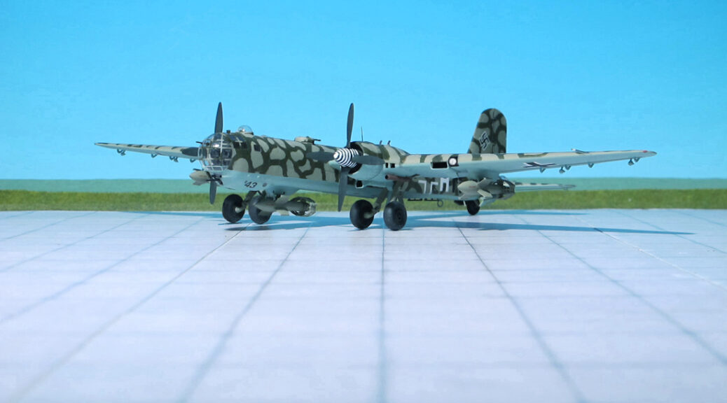
POWER PLANT: Two Daimler- Benz DB 610 “power systems”, each one created from a twinned-pair of Daimler-Benz DB 610A-1/B-1 liquid-cooled engines, rated at 2,950 hp each
PERFORMANCE: 303 mph at 19,685 ft
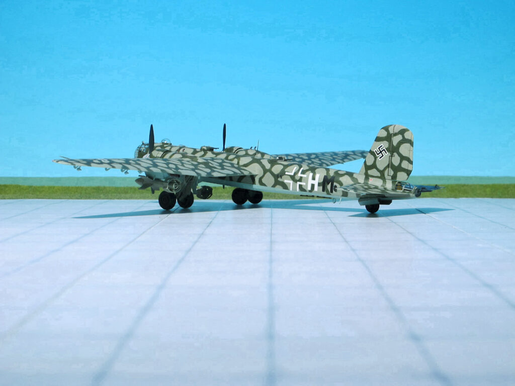
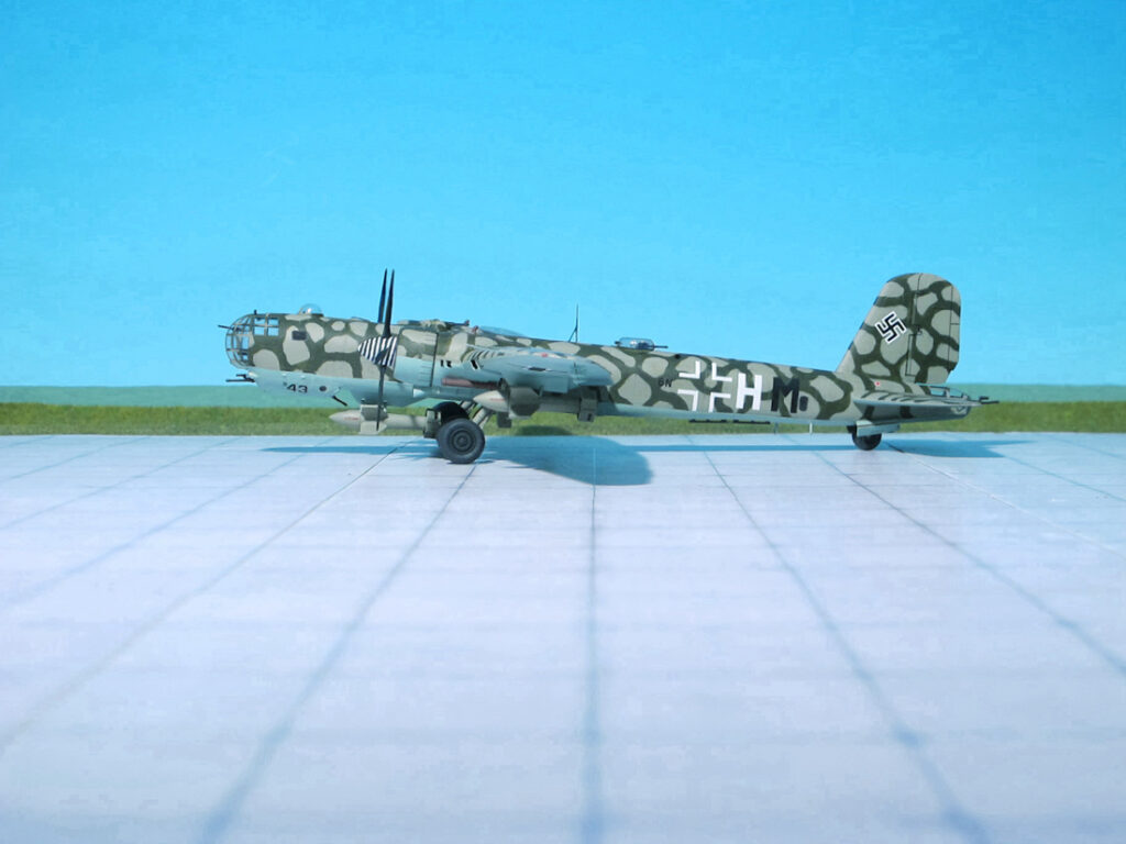
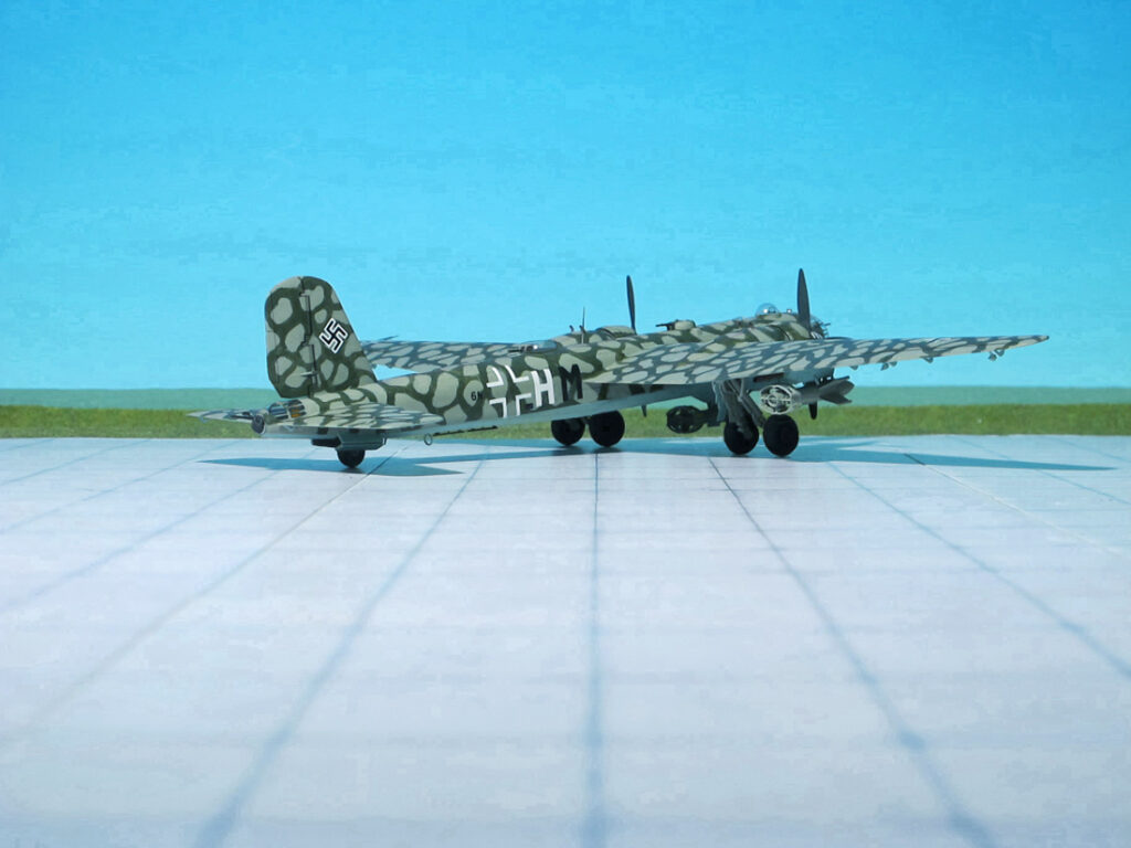
COMMENT: The Heinkel He 177 “Greif” (“Griffin”) was a long-range heavy bomber flown by the German Luftwaffe during World War II. The He 177 was the only operational long-range heavy bomber available to the Luftwaffe during the war years that had a payload/range capability similar to the four-engined heavy bombers flown by the USAAF and RAF in the European theatre; it had higher cruising and maximum speeds.
Designed to a 1936 requirement known as “Bomber A”, the aircraft was originally intended to be a purely strategic bomber intended to support a long-term bombing campaign against Soviet industry in the Urals. In spite of its large wingspan, the design was limited to two engines. During the design, Luftwaffe doctrine came to stress the use of moderate-angle dive-bombing, or “glide bombing”, to improve accuracy. Applying the changes needed for this type of attack to such a large aircraft was unrealistic.
To deliver the power required from only two engines on an aircraft this large, engines of at least 2,000 hp were needed. Such designs were not well established and the Daimler-Benz DB 606 “power system”, combined with the cooling and maintenance problems caused by the tight nacelles, caused the engines to be infamous for catching fire in flight. Early models gained the nicknames Reichsfeuerzeug“ (“Reich’s lighter”) from Luftwaffe aircrew.
On 9 November 1939, the first prototype, the He 177 V1, was flown. Further seven prototypes were completed until 1942, followed by 35 pre-production He 177 A-0s and 130 He 177 A-1s. The early aircraft in this batch were used for further trials, and after a brief and unhappy operational debut the remainder were withdrawn from service. From late 1942 they were replaced by He 177 A-3s. Starting in August 1943, all He 177’s delivered had an extended rear to both instill greater stability for bombing and to offset the slightly lengthened engine nacelles. Most of the short-fuselage A-3s were rebuilt to the longer standard . From November 1942 to June 1944 612 He 177A-3 were built resp. converted (from short fuselage to long fuselage). These were followed by 350 He 177A-5.
The type matured into a usable design but was too late in the war to play an important role. It was built and used in some numbers, especially on the Eastern Front where its range and cruising altitudes in excess of 19,690 ft was particularly useful. So, losses were relatively light. The Soviet Air Force, equipped mainly for low-level interception and ground-attack roles, could do little to hinder the high-flying bombers. In contrast the He 177 saw considerably less use on the Western Front late in 1944.
As the war progressed, He 177 operations became increasingly ineffective. Fuel and personnel shortages presented difficulties, and He 177s were sitting on airfields all over Europe awaiting new engines or engine-related modifications. Constant attacks of the Allied against Luftwaffe long-range combat units in France made continuous operations difficult.
In common with most piston-engined German bombers, the He 177 was grounded from the summer of 1944 due to the implementation of the Emergency Fighter Program (Jäger Notprogramm). Until November 1944, 1,153 He 177 in several subtypes were built by Arado and Heinkel.
One Heinkel He 177A-0, one A-3, and two A-5 were rebuilt as Heinkel He 177 B prototypes from December 1943 to July 1944. From the beginning these aircraft were designed as a four-engined development with four Daimler-Benz DB 603 in separate nacelles instead of the “coupled engine” powered He 177 A-series. Further plans show that these engine arrangements were postulated for the successor, the Heinkel He 277.
The Heinkel He 177 A-5/R2, shown here, belongs to the 4./KG 100, stationed at Chateaudun, France. This version was optimized for Ruhrstahl Fritz X and Henschel Hs 293 guided bombs and equipped with FuG 203 Kehl-Straßburg control gear.
RUHRSTAHL FRITZ X
Ruhrstahl Fritz X was the most common name for a German guided anti-ship glide bomb used during WWII. Fritz X was the world’s first precision guided weapon deployed in combat and the first to sink a ship in combat. Fritz X was a nickname used both by Allied and German Luftwaffe personnel. Alternative names include Ruhrstahl SD 1400 X, Kramer X-1, PC 1400X or FX 1400 (the latter, along with the unguided PC 1400 Fritz nickname, is the origin for the name “Fritz X”.
Fritz X was a further development of the PC 1400 (Panzersprengbombe, Cylindrisch 1,400 kg) armour-piercing high-explosive bomb, itself bearing the nickname Fritz. It was a penetration weapon intended to be used against armored targets such as heavy cruisers and battleships. It was given a more aerodynamic nose, four stub wings, and a box shaped tail unit consisting of a roughly 12-sided annular set of fixed surfaces and a cruciform tail with thick surfaces within the annulus, which contained the Fritz X‘s aerodynamic controls.
The Luftwaffe recognized the difficulty of hitting moving ships during the Spanish Civil War. Dipl. engineer Max Kramer, who worked at the Deutsche Versuchsanstalt für Luftfahrt (DVL) had been experimenting since 1938 with remote-controlled free-falling 250 kg bombs and in 1939 fitted radio-controlled spoilers. In 1940, Ruhrstahl AG was invited to join the development, since they already had experience in the development and production of unguided bombs.
Fritz X was guided by a FuG 203 Kehl-Straßburg radio control link, which sent signals to the movable spoilers in the thick vertical and horizontal tail fin surfaces, within the annular tail fin structure. This control system was also used for the unarmored, rocket-boosted Henschel Hs 293 anti-ship ordnance, itself first deployed on 25 August 1943. The Kehl-Straßburg receiver antenna installations on the Fritz X were aerodynamically integrated into the trailing edge of the annular surfaces of the tail fin, non-metallically encapsulated within a quartet of “bulged” sections in the trailing edge. This design feature of the FuG 230 Kehl-Straßburg receiver installation is not entirely unlike the Azon (Azimuth only ) US contemporary guided bomb, which had its own receiving antennas placed in the quartet of diagonal struts bracing the fixed sections of its tail fins.
Minimum launch height was 13,000 ft – although 18,000 ft was preferred – and a range of 5 km was necessary. As it was an MCLOS (manual command to line of sight)-guidance ordnance design, the operator had to keep the bomb in sight at all times (a tail flare was provided, as with the Azon, to assist the operator in tracking the weapon) and the control aircraft had to hold course, which made evading gunfire or fighters impossible. Approximately 1,400 examples, including trial models, were produced (Ref.: 24).
Heinkel He 177A-5/R2 “Greif” (“Griffin”) with Ruhrstahl Fritz X, 4./KG 100
Heinkel He 177A-5/R2 “Greif” (“Griffin”) with Ruhrstahl Fritz X, 4./KG 100
Heinkel He 177A-5/R2 “Greif” (“Griffin”) with Ruhrstahl Fritz X, 4./KG 100
Heinkel He 177A-5/R2 “Greif” (“Griffin”) with Ruhrstahl Fritz X, 4./KG 100
Heinkel He 177A-5/R2 “Greif” (“Griffin”) with Ruhrstahl Fritz X, 4./KG 100
Heinkel He 177A-5/R2 “Greif” (“Griffin”) with Ruhrstahl Fritz X, 4./KG 100
Heinkel He 177A-5/R2 “Greif” (“Griffin”) with Ruhrstahl Fritz X, 4./KG 100
Heinkel He 177A-5/R2 “Greif” (“Griffin”) with Ruhrstahl Fritz X, 4./KG 100
Heinkel He 177A-5/R2 “Greif” (“Griffin”) with Ruhrstahl Fritz X, 4./KG 100
Heinkel He 177A-5/R2 “Greif” (“Griffin”) with Ruhrstahl Fritz X, 4./KG 100
Heinkel He 177A-5/R2 “Greif” (“Griffin”) with Ruhrstahl Fritz X, 4./KG 100
Heinkel He 177A-5/R2 “Greif” (“Griffin”) with Ruhrstahl Fritz X, 4./KG 100
Heinkel He 177A-5/R2 “Greif” (“Griffin”) with Ruhrstahl Fritz X, 4./KG 100
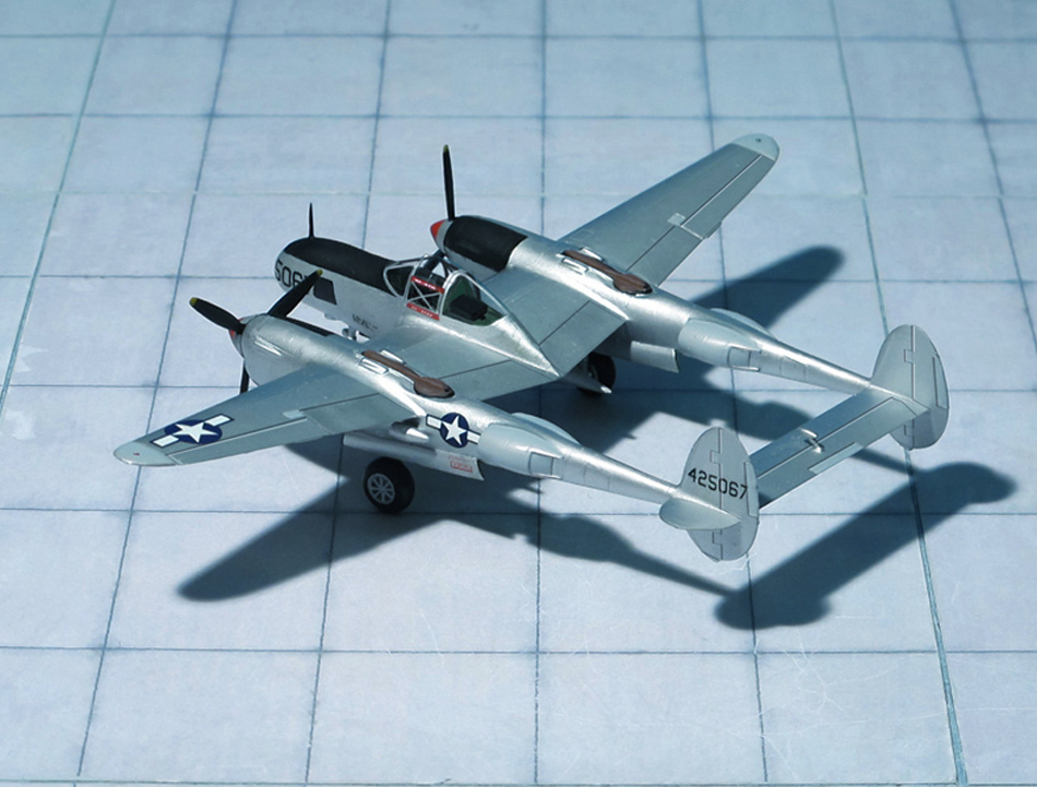
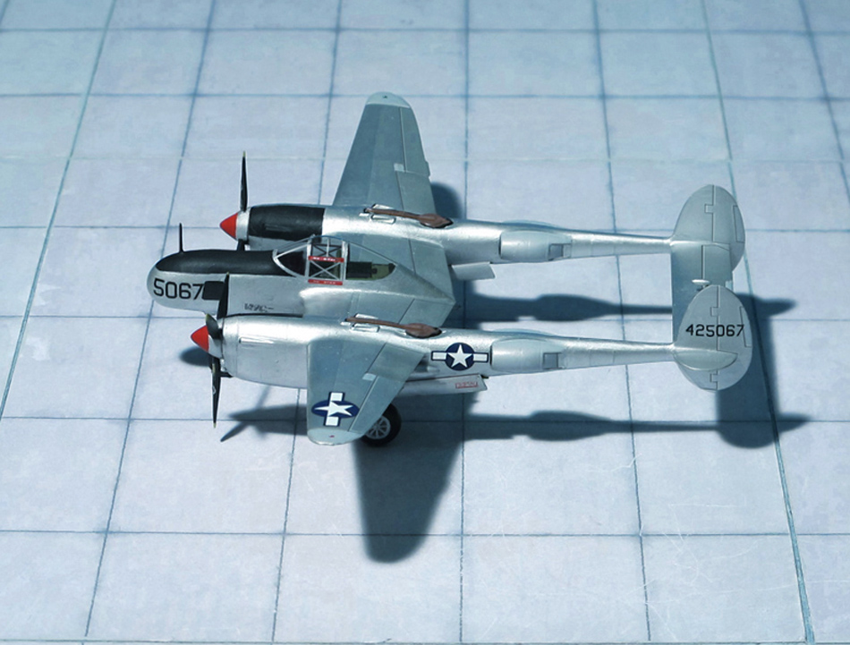
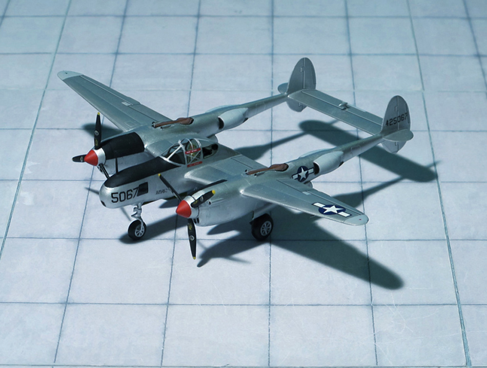
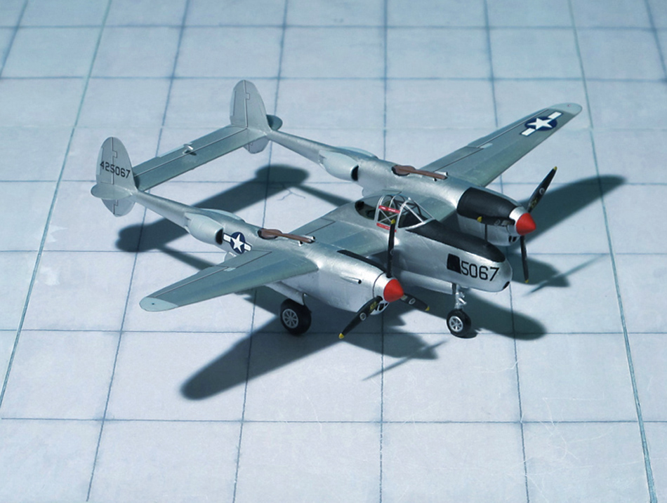
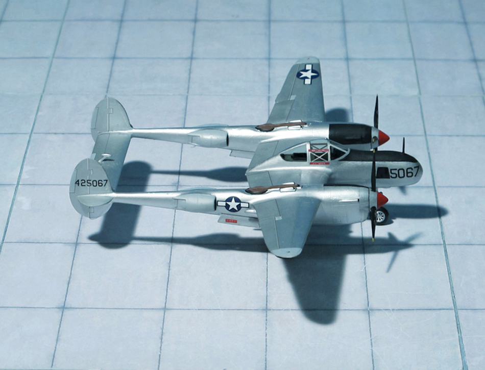
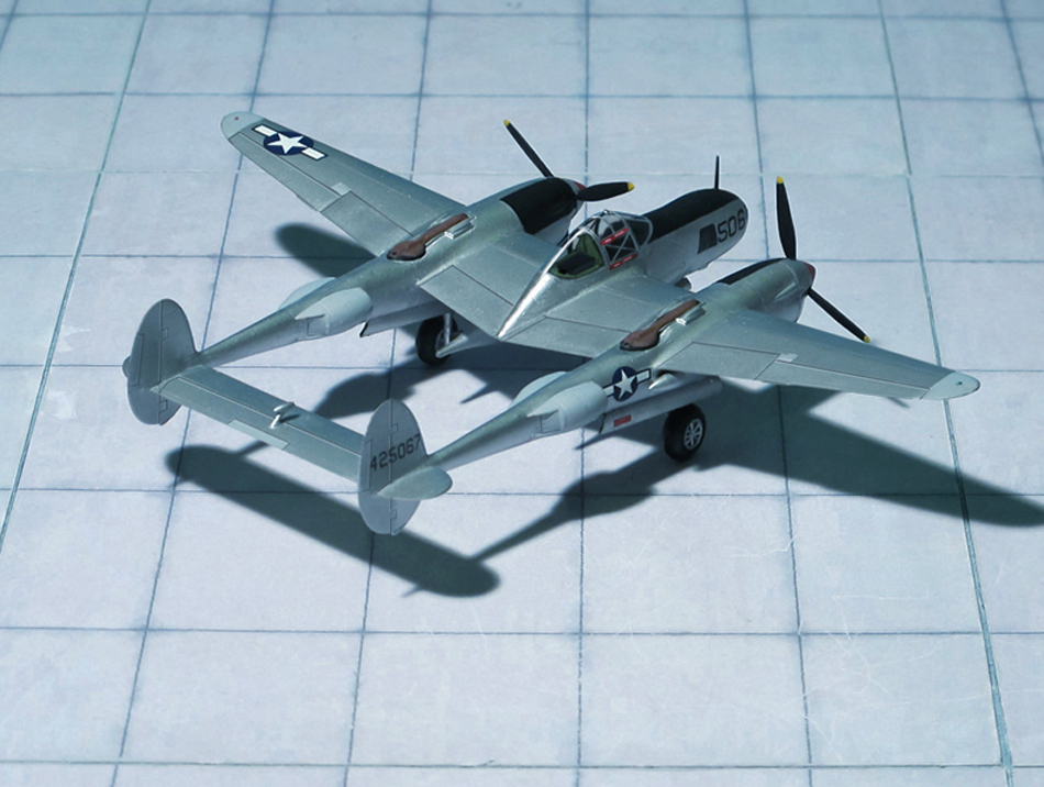
POWER PLANT: Two Allison V-1710-111/113 liquid-cooled turbocharged engines, rated at 1,600 hp each
PERFORMANCE: 414 mph at 25,000 ft
COMMENT: The Lockheed P-38 Lightning was an American single-seat, piston-engined fighter aircraft that was used during World War II. Developed for the United States Army Air Corps, the P-38 had distinctive twin booms and a central nacell containing the cockpit and armament. Along with its use as a general fighter, the P-38 was utilized in various aerial combat roles including as a highly effective fighter-bomber, a night-fighter and as a long-range escort fighter when equipped with drop tanks. The P-38 was also used as a bomber-pathfinder, guiding streams of medium and heavy bombers; or even other P-38s, equipped with bombs, to their targets. Used in the aerial reconnaissance role, the P-38 accounted for 90 percent of the aerial film captured over Europe.
The first combat-capable Lightning was the P-38E which rolled out of the factory in October 1941. Because of the versatility, redundant engines, and especially high speed and high altitude characteristics of the aircraft, as with later variants over a hundred P-38Es were completed in the factory or converted in the field to a photoreconnaissance variant, the F-4, in which the guns were replaced by four cameras. Most of these early reconnaissance Lightnings were retained stateside for training, but the F-4 was the first Lightning to be used in action in April 1942. In total 99 P-38E were converted to F-4.
After 210 P-38Es were built, they were followed, starting in February 1942, by the Lockheed P-38F. Its photo reconnaissance version was the Lockheed F-4A Lightning of which 90 aircraft were built.
The Lockheed P-38F was followed in June 1942 by the P-38G, using more powerful Allisons of 1,400 hp each and equipped with a better radio. The reconnaissance variant was the F-5A, 181 aircraft were built.
The following 323 reconnaissance versions F-5B and F-5C were converted from Lightning P-38J. Major differences were the introduction of uprated Allison engines as well as a new the turbosupercharger intercooler system.
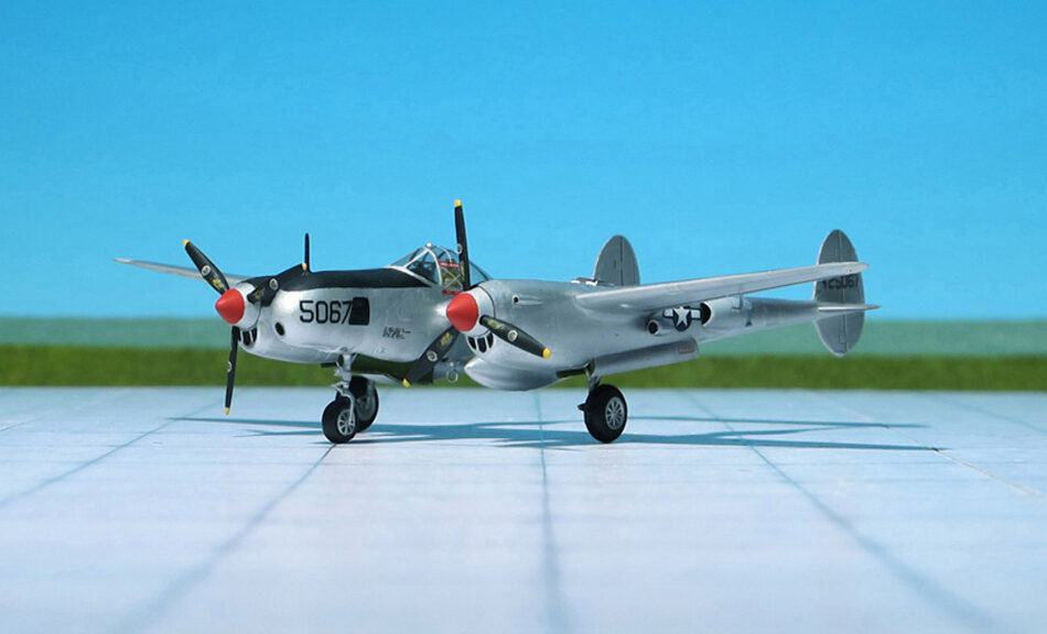
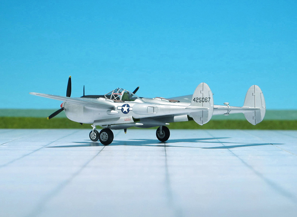
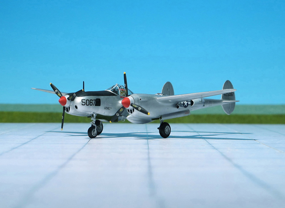
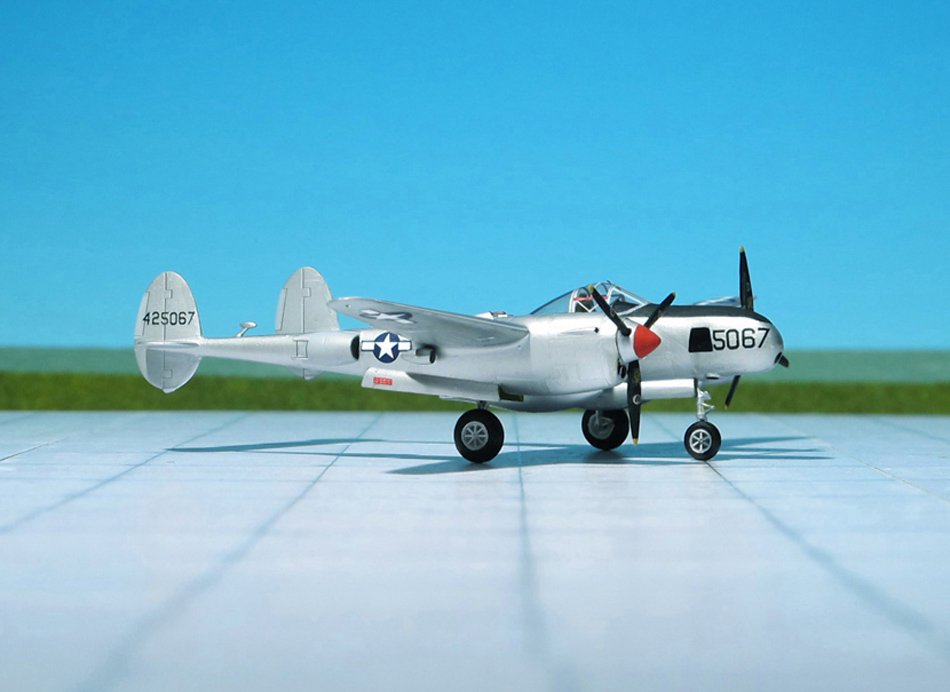
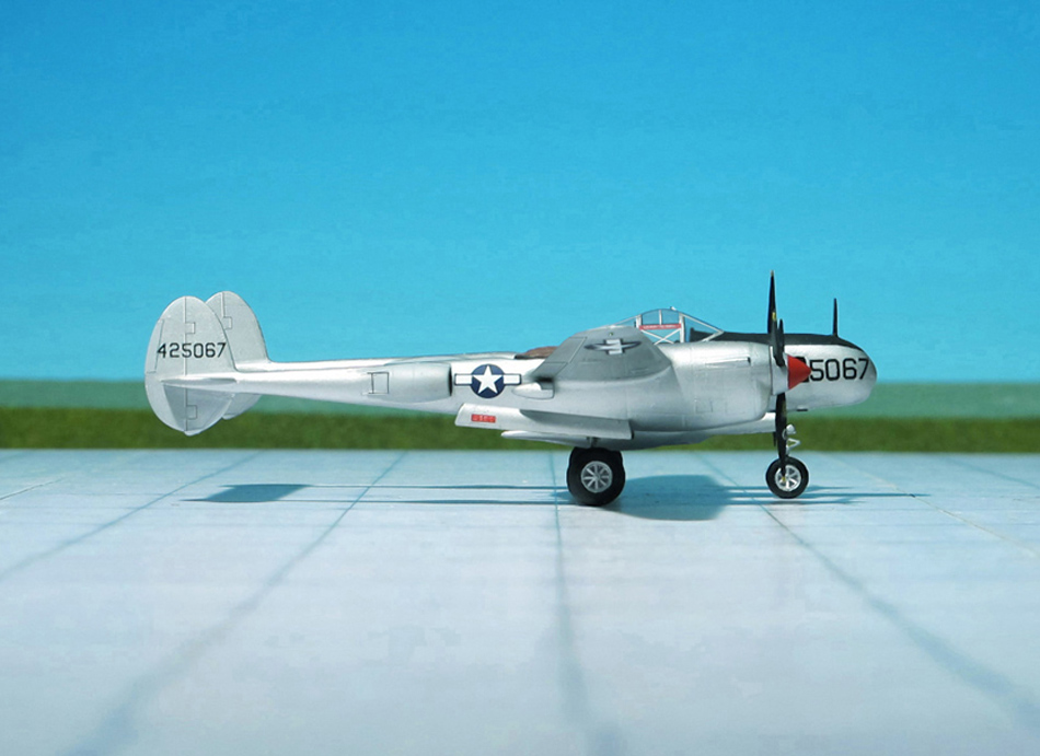
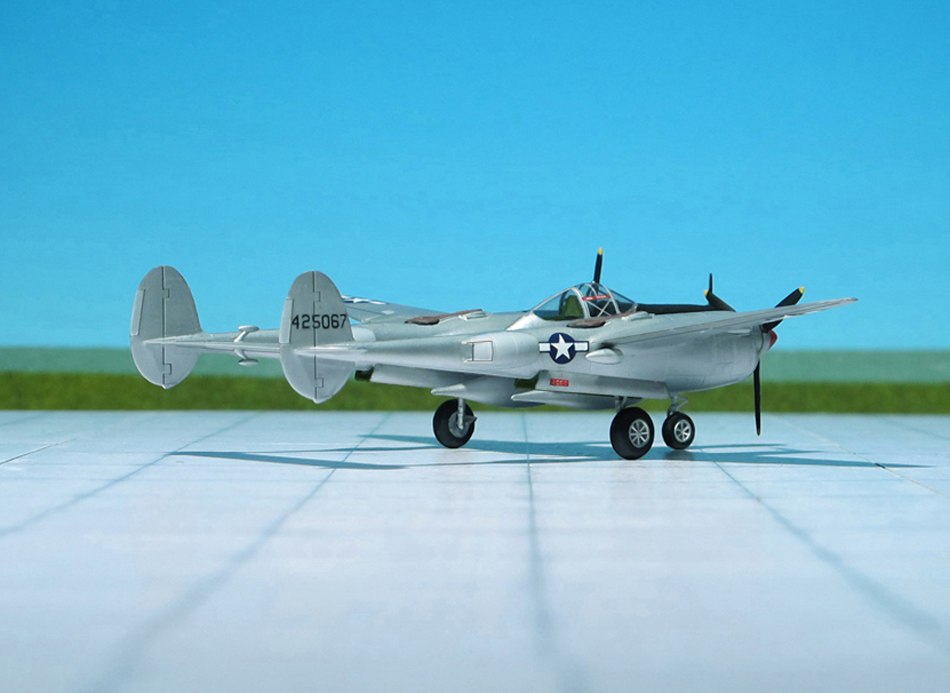
The P-38L Lightning was the most numerous variant of the Lightning, with 3,923 built. It entered service with the USAAF in June 1944, in time to support the Allied invasion of France on D-Day. The F-5E reconnaissance variants were converted from the P-38J and P-38L. In total 705 aircraft had been converted for photographic reconnaisssance duties. The aircraft shown here probably belongs tot he 7th Photographic Reconnaisance Group (PRG), 8th USAAF, stationed at Chalgrove, England (Ref.: 24).
Lockheed F-5E “Lightning”, 7th PRG, 8th USAAF, England
Lockheed F-5E “Lightning”, 7th PRG, 8th USAAF, England
Lockheed F-5E “Lightning”, 7th PRG, 8th USAAF, England
Lockheed F-5E “Lightning”, 7th PRG, 8th USAAF, England
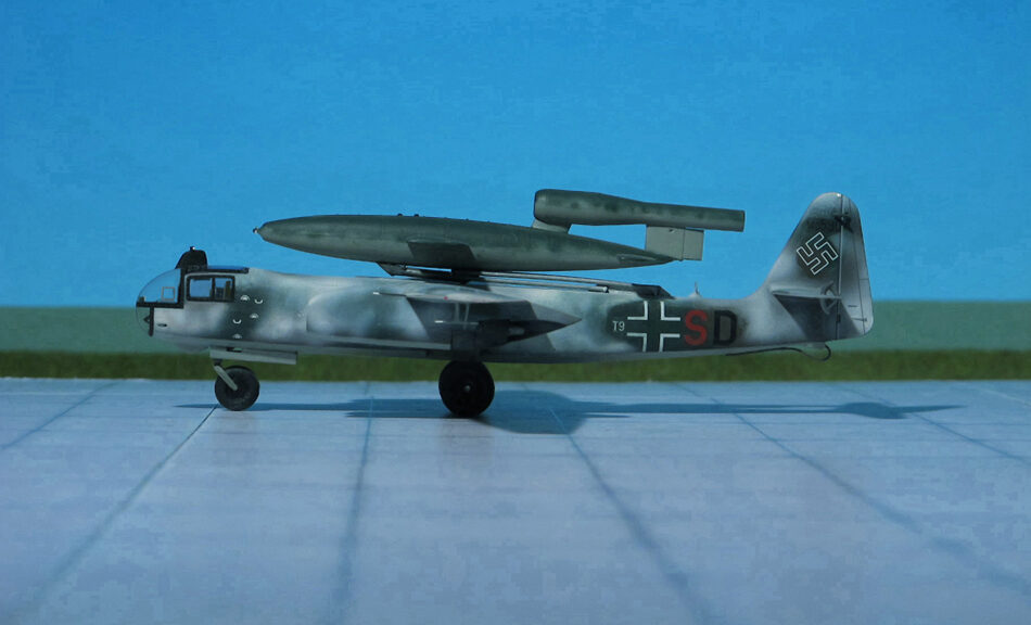
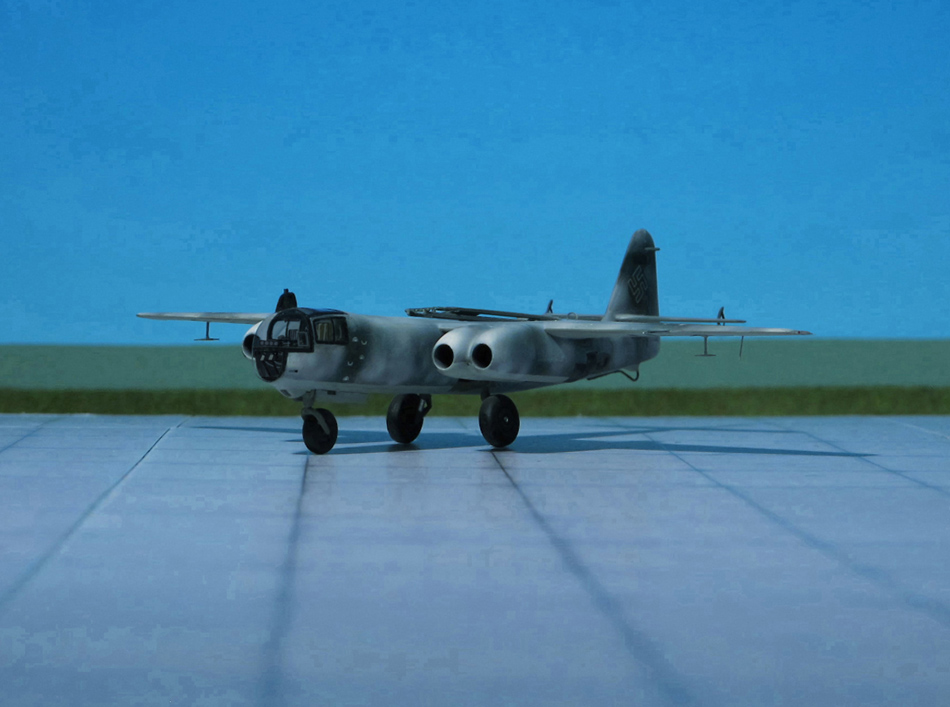
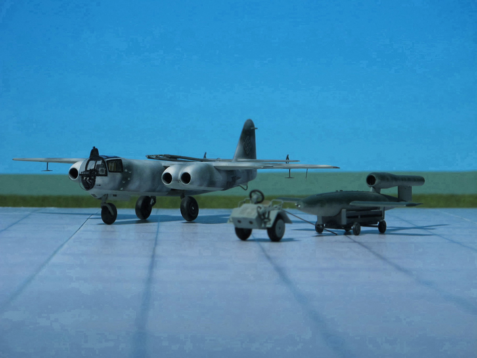
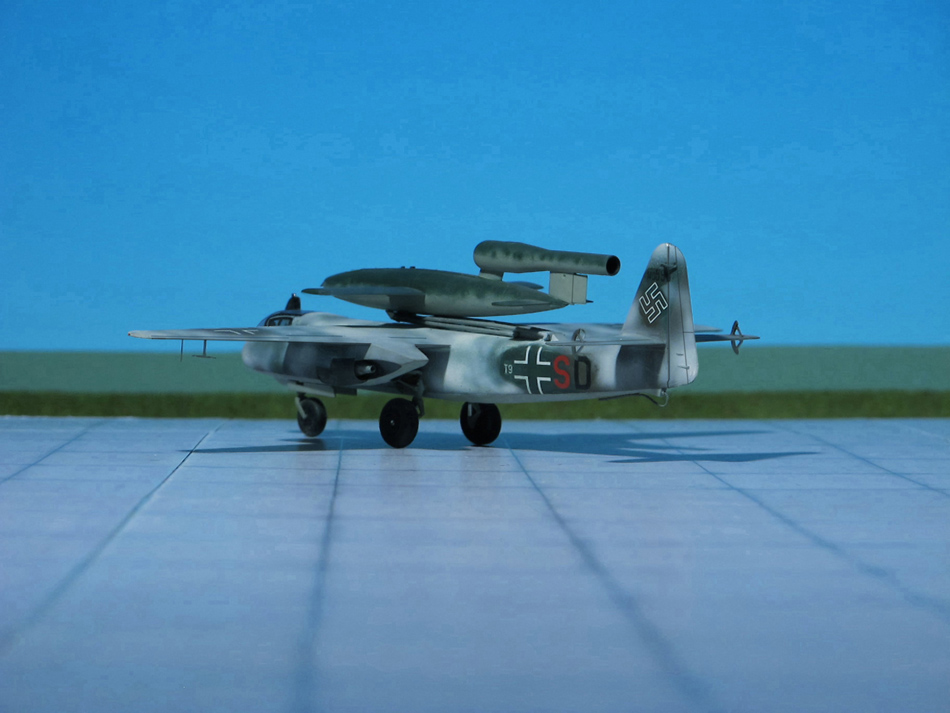
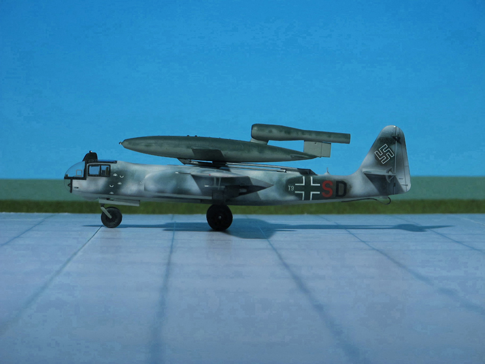
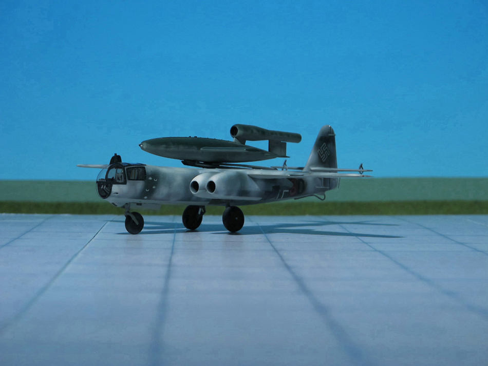
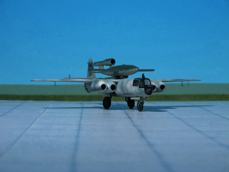
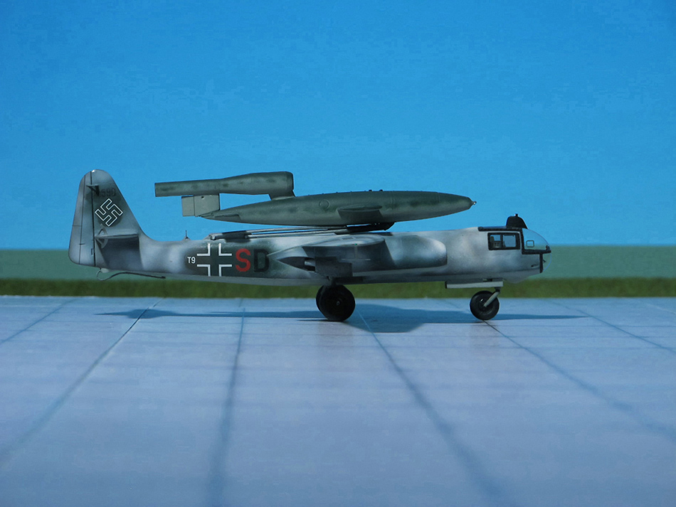
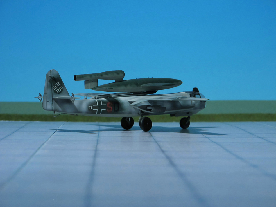
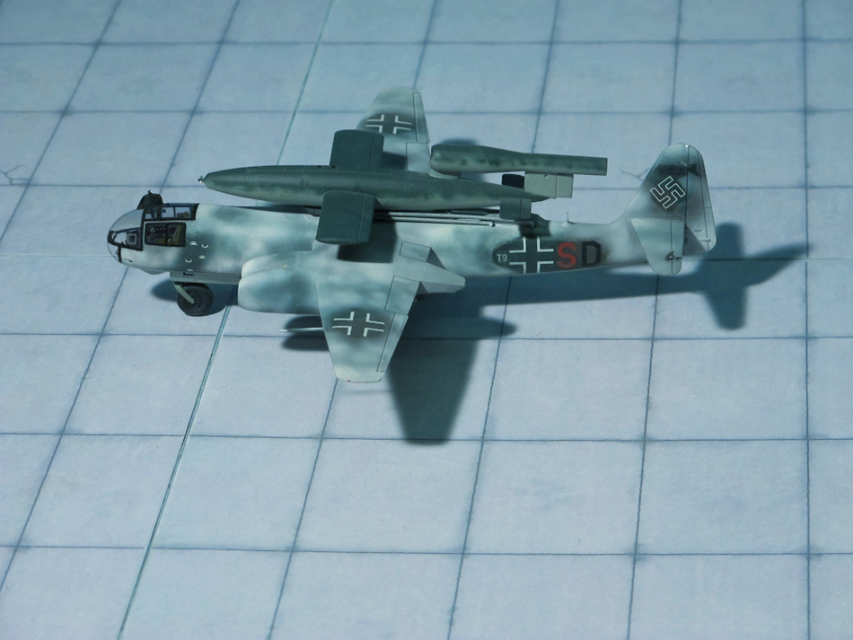
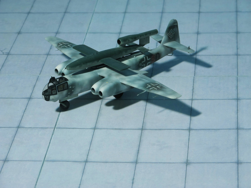
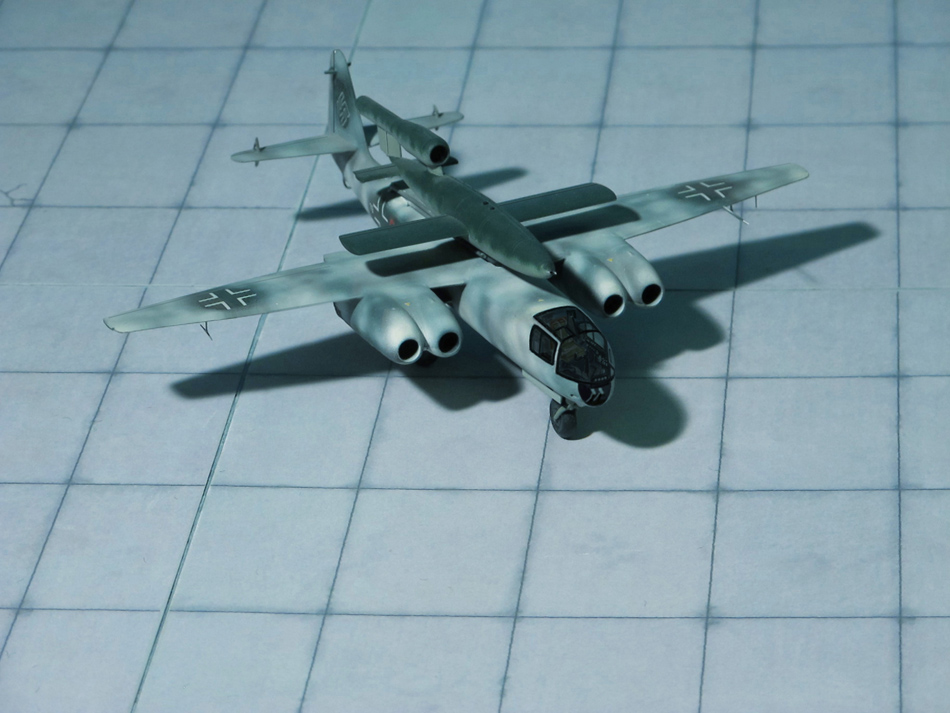
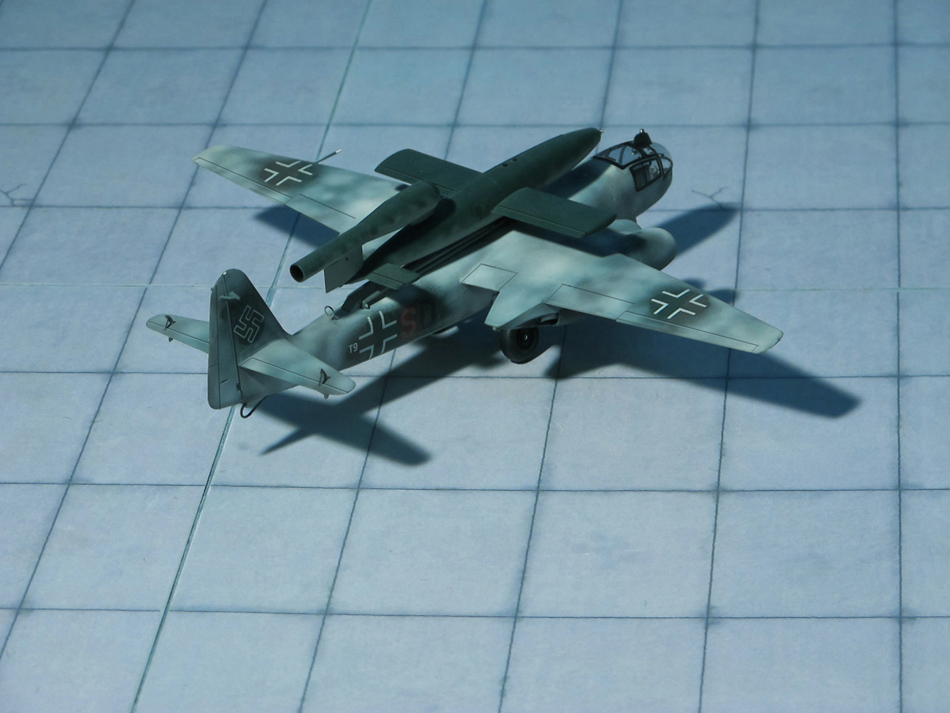
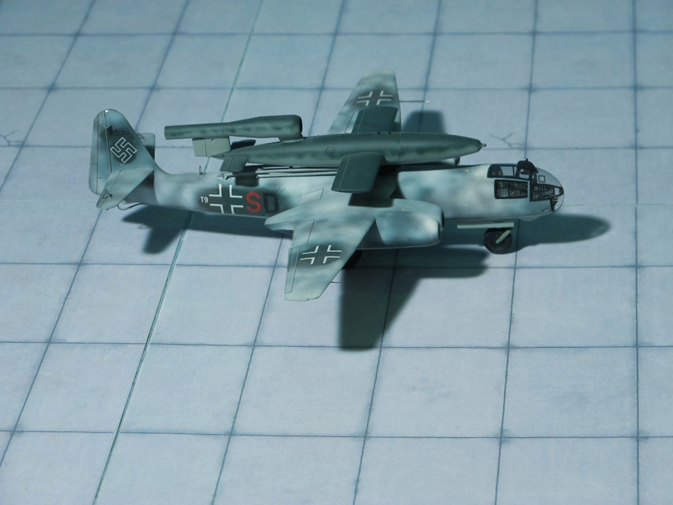
TYPE: Turbojet driven bomber, Mistel (Mistletoe) component ACCOMMODATION: Pilot only POWER PLANT: Four BMW 003A-2 turbojet engines, rated at 800 kp thrust each PERFORMANCE: 460 mph at 20,000 ft COMMENT: The Arado Ar 234 Blitz (Lightning) was the world’s first operational turbojet-powered bomber, built by the German Arado company during World War II.
Produced in limited numbers it was used almost entirely for aerial reconnaissance. In its few uses as a bomber it proved to be nearly impossible to intercept. It was the last German Luftwaffe aircraft to fly over the UK during the war, in April 1945
The Ar 234 was built in various versions: Ar 234A with two turbojet engines, Ar 234B with two turbojet engines or for engines in separat nacelles and Ar 234C with four engines mounted in a pair of twin-engine nacelles and a purely rocket-engine-driven Ar 234R. Of each of these various versions sub-types were built or planned.
The Arado Ar 234C was equipped with four lighter weight BMW 003A turbojet engines mounted in a pair of twin-engine nacelles based on basis of the eighth prototype. The primary reason for changing the engienes was to free up the Junkers Jumo 004 turbojets for use by the Messerschmitt Me 262, but the change improved overall thrust to nearly 3.2 tonnes with all four BMW turbojets at full take-off power, especially useful for take-off and climb-to-altitude performance. An improved cockpit design, with a slightly bulged outline for the upper contour integrating a swept-back fairing for the periscope, used a simplified window design with fewer glazed panels for ease of production. The four BMW jet engines gave about 20% greater airspeed than the Ar 234B series airframes, and the faster climb to altitude meant more efficient flight and increased range.
Although an operational test squadron was being prepared, only 14 C-series airframes had been completed by the end of the war, of which fewer than half had engines. Some were found at the end of the war sitting in the open, complete but for empty engine nacelles.Comprehensive flight testing of the new sub-type had yet to begin when Germany surrendered. Three basic variants of the C-series were planned for initial construction, with several more laid out as detailed proposals. Some of these would have had a pair of the higher thrust, but heavier Heinkel/Hirth HeS 011turbojet engines, while others were intended to feature swept or “crescent”-type wings.
There were plans, not put into practice, to use the Arado 234C turbojet bomber to launch V-1s either by towing them aloft or by launching them from a “piggy back” position (in the manner of the Mistel (Mistletoe), but in reverse) atop the aircraft. In the latter configuration, a pilot-controlled, hydraulically operated dorsal trapeze mechanism would elevate the missile on the trapeze’s launch cradle about 2.4 m clear of the Ar 234’s upper fuselage. This was necessary to avoid damaging the mother craft’s fuselage and tail surfaces when the pulsejet ignited, as well as to ensure a “clean” airflow for the Argus motor’s intake.
FIESELER Fi 103 V-1 FLYING BOMB
TYPE: Unmanned Flying bomb
ACCOMMODATION: None
POWER PLANT: One Argus As 109-014 pulsejet, rated at 330 kp thrust PERFORMANCE: 400 mph at 3000 ft
COMMENT: The V-1 flying bomb (Vergeltungswaffe 1, Vengeance Weapon 1) was an early cruise missle and the only production aircraft to use a pulsejet for power. Its official RLM (Reichsluftwsffenministerium, Reich Aviation ministry) designation was Fi 103 was also known to the Allies as the buzz bomb or doodlebug and in Germany as Kirschkern (cherry stone) or Maikäfer (maybug).The V-1 was deployed for the terror bombing of London. It was developed at Peenemünde Army Research Center in 1939 by the German Luftwaffe at the beginning of the WW II. Because of its limited range, the thousands of V-1 missiles launched into England were fired from launch favilities along the French and Dutch coasts.
The V-1 was designed with a fuselage constructed mainly of welded sheet steel and wings built of plywood. The simple Schmidt/Argus-built pulsejet engine pulsed 50 times per second, and the characteristic buzzing sound gave rise to the colloquial names buzz bomb” or doodlebug.
The Argus pulsejet‘s major components included the nacelle, fuel jets, flap valve grid, mixing chamber Venturi, tail pipe and spark plug. Compressed air forced gasoline from the 640 l fuel tank through the fuel jets, consisting of three banks of atomizers with three nozzles each. Argus’ pressurized fuel system negated the need for a fuel pump. These nine atomizing nozzles were in front of the air inlet valve system where it mixed with air before entering the chamber. A throttle valve, connected to altitude and ram pressure instruments, controlled fuel flow. Schmidt’s spring-controlled flap valve system provided an efficient straight path for incoming air. The flaps momentarily closed after each explosion, the resultant gas compressed in the Venturi chamber, and its tapered portion accelerated the exhaust gases creating thrust. The operation proceeded at a rate of 42 cycles per second. The engine made its first flight aboard a Gotha Go 145 biplane on 30 April 1941.
The V-1 guidance system used a simple autopilot developed to regulate altitude and airspeed. A pair of gyroscopes controlled yaw and pitch, while azimuth was maintained by a magnetic compass. Altitude was maintained by a barometric device.Two spherical tanks contained compressed air that drove the gyros, operated the pneumatic servo-motors controlling the rudder and elevator, and pressurized the fuel system. The warhead consisted of 850 kg of Amatol, 52A+ high-grade blast-effective explosive with three fuses. An electrical fuse could be triggered by nose or belly impact. Another fuse was a slow-acting mechanical fuse allowing deeper penetration into the ground, regardless of the altitude. The third fuse was a delayed action fuse, set to go off two hours after launch.
Almost 30,000 V-1s were built; by March 1944, they were each produced in 350 hours (including 120 for the autopilot), at a cost of just 4% of a V-2, which delivered a comparable payload. Approximately 10,000 were fired at England; 2,419 reached London (Ref.: 7, 24).
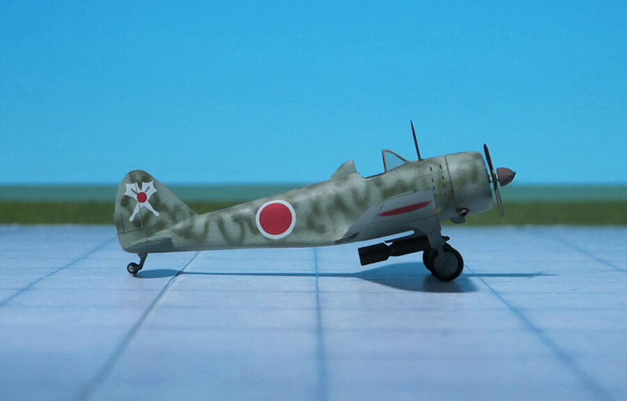
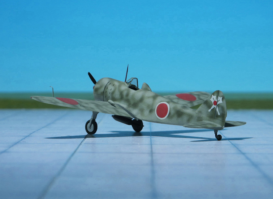
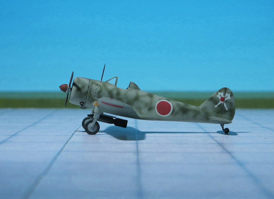
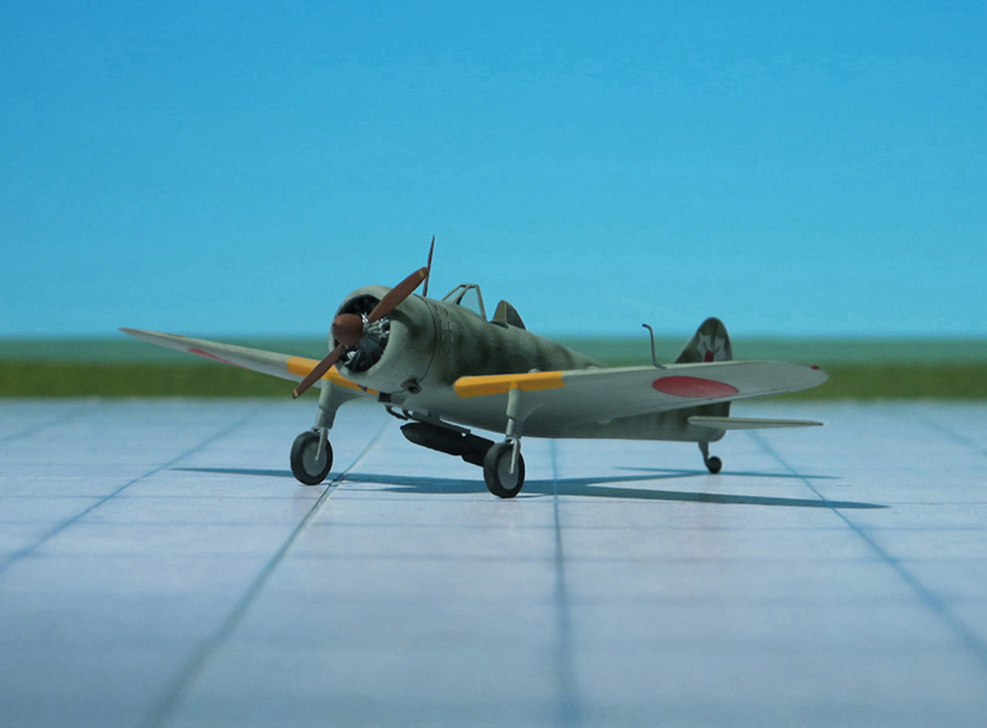
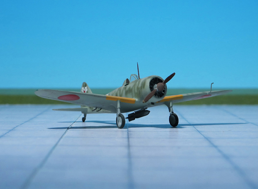
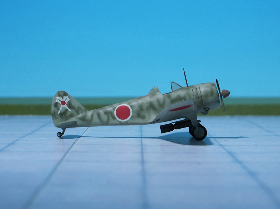
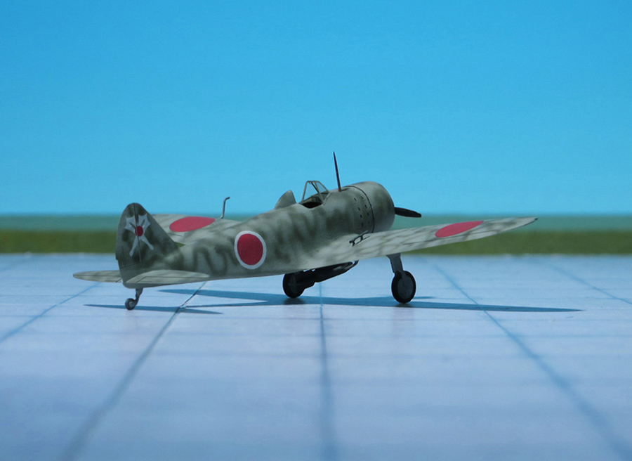
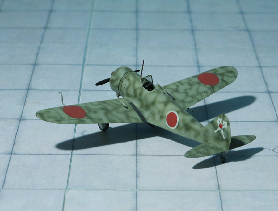
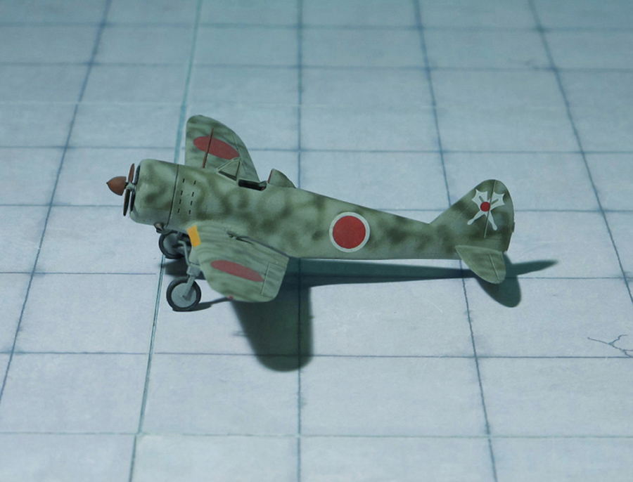
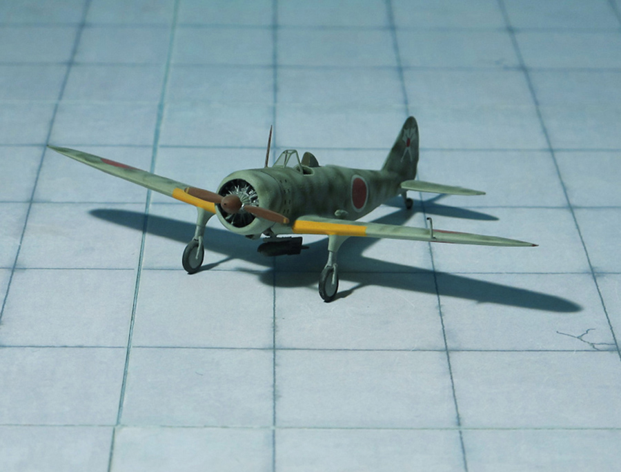
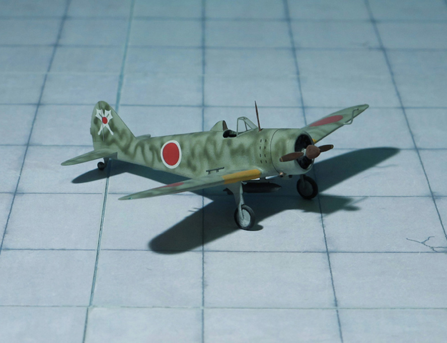
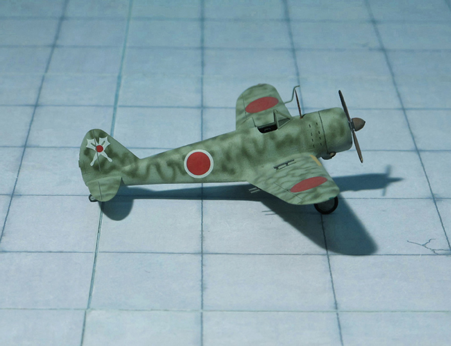
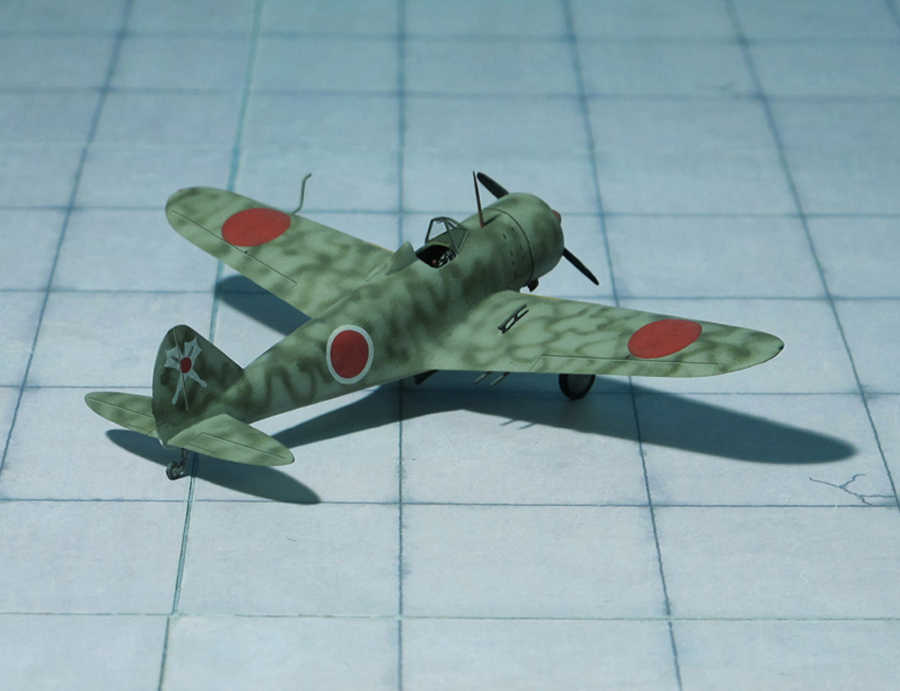
POWER PLANT: One Hitachi 22 (Ha-23) radial engine, rated at 510 hp
PERFORMANCE: 211 mph
COMMENT: The production of the Army Type 2 Advanced Trainer Ki-79 (Allied code Nate) at the Mansyu plant in Manchuria, occupied by the Japanese, began on January 19, 1943 with the production under license by Nakajima of two variants at once: the Ki-79a single-seat trainer and the Ki-79b two-seat trainer. Both versions had an all-metal semi-monocoque design with low load-bearing surfaces and non-retractable landing gear, exactly the same as that of the Nakajima Ki-27 fighter, since the airframe design was almost completely transferred to the new aircraft. The only significant difference in the trainer was the open cockpit. Since the Hitachi engine was somewhat lighter than its predecessor, the Nakajima Ki-27, despite its almost identical diameter, had to be moved forward a little to maintain the same alignment of the aircraft. Because of this, the length of the serial Ki-79 increased by 0.32 m compared to the length of the three prototypes, where the engine was not moved and the dimensions remained the same as that of the Ki-27. Two-bladed wooden propeller with a diameter of 2.50 m or three-blade wooden propeller with variable pitch were provided. The Mansu Ki-79 trainer was a cantilever monoplane with a low wing along with a cantilever tailplane.
A total of 1,329 aircraft were built in four sub-versions: The single seat Ki-79a with an Hitachi Ha.13a-I engine and the Ki-79c with an Ha.13a-III engine. The two-seat versions Ki-79b had a Hitachi Ha.13a-I engine and the Ki-79d version with a Ha.13a-III engine. Manyu Ki-79a and Ki-79c were of all-metal construction. The versions Ki-79b and Ki-79d had a mixed structure with steel fuselage frame with plywood sheathing and a wooden wing.
The Mansyu Ki-79 were seen at the Army Junior Flight Schools (Rikugun Shonen Hiko Gakko) in Tokyo, Otsu and Onta in Japan, where young pilots trained before becoming an Imperial Japanese Army Air Force (IJAAF) cadet. At the end of the war, these schools trained future members of the Shinpū Tokubetsu Kōgekitai, (Divine Wind Special Attack Unit), part of the Special Assault Units of the IJAAF, known as Kamikaze. They flew sicide attacks for the Empire of Japan against Allied naval vessels in the closing stages of the Pacific campaigne of World War II, intending to destroy warships more effectively than with conventional air attacks.
Kamikaze aircraft were essentially pilot-guided explosive missles, purpose-built or converted from conventional aircraft. Even trainers as the Mansyu Ki-79c were used alongside with older aircraft such as the Tachikawa Ki-9, Ki-7 and Ki-55. Most aircraft were equipped with one 250 kg bomb under the fuselage.
Also the Imperial Japanese Army Air Force also had similar units as the Rikugun Koku Tokubetsu Kogekitan (Army Special Assault Unit). Their purpose was to ram Boeing B-29 Superfortress mid air. These units were called Thanatari (Thunderstorm) (Ref: 1, 24).
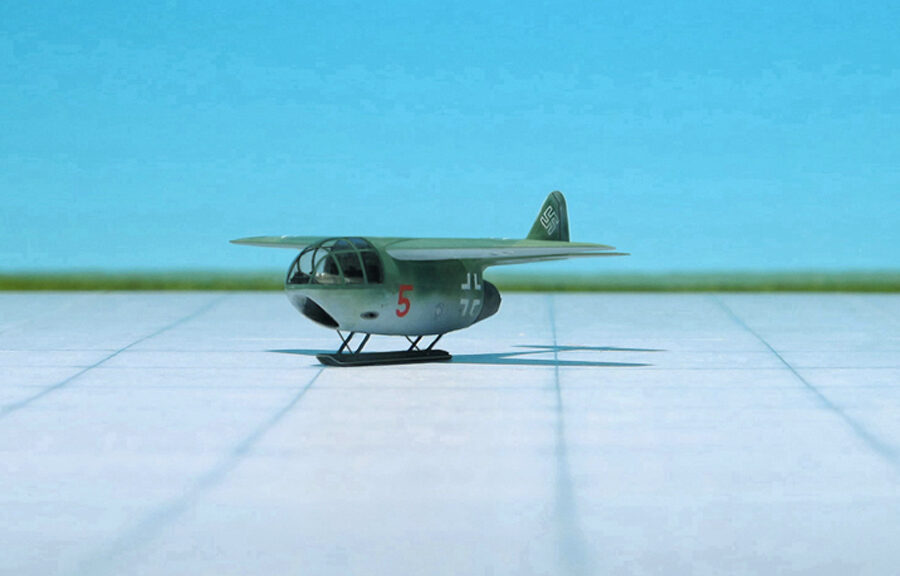
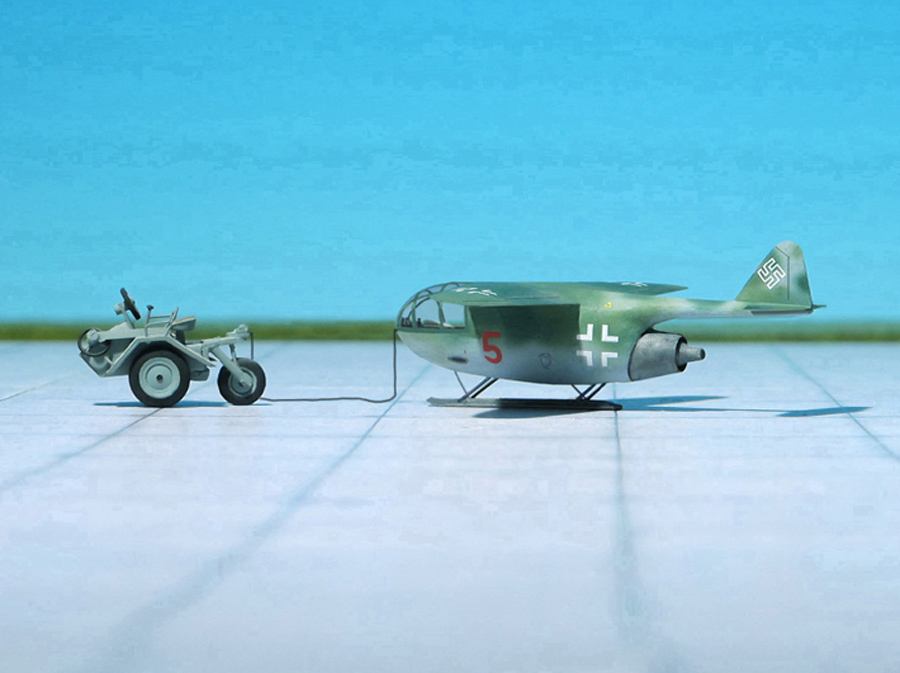
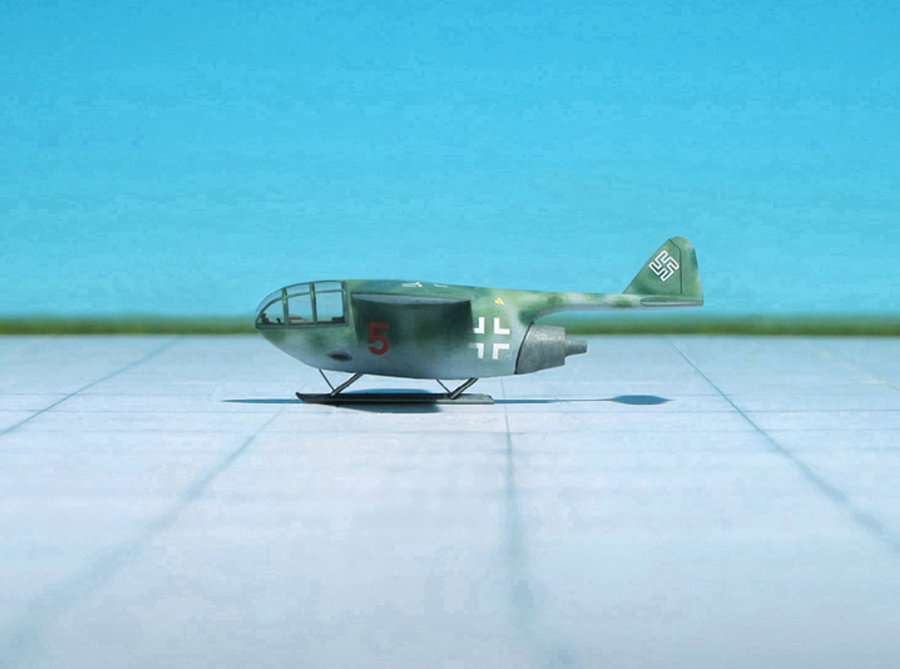
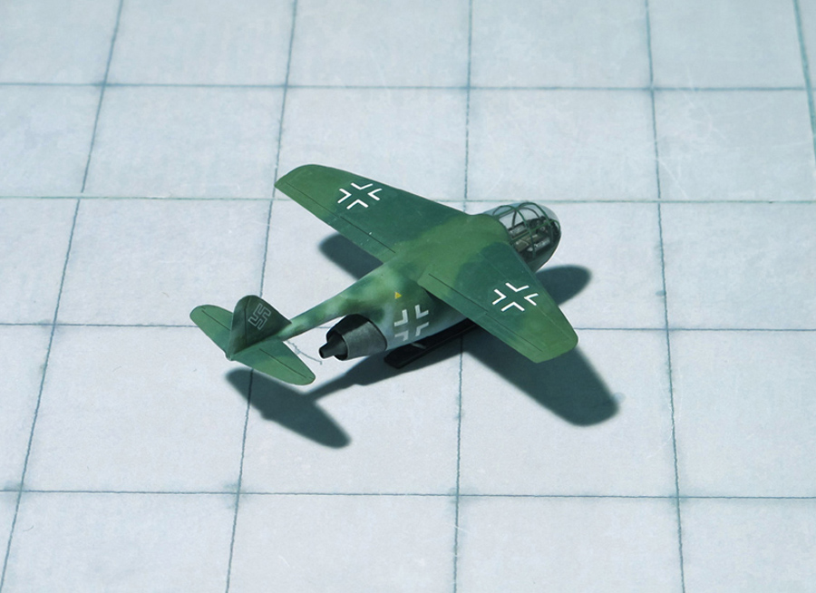
POWER PLANT: One BMW 003 A-1 turbojet engine, rated at 800 kp thrust
PERFORMANCE: No data available
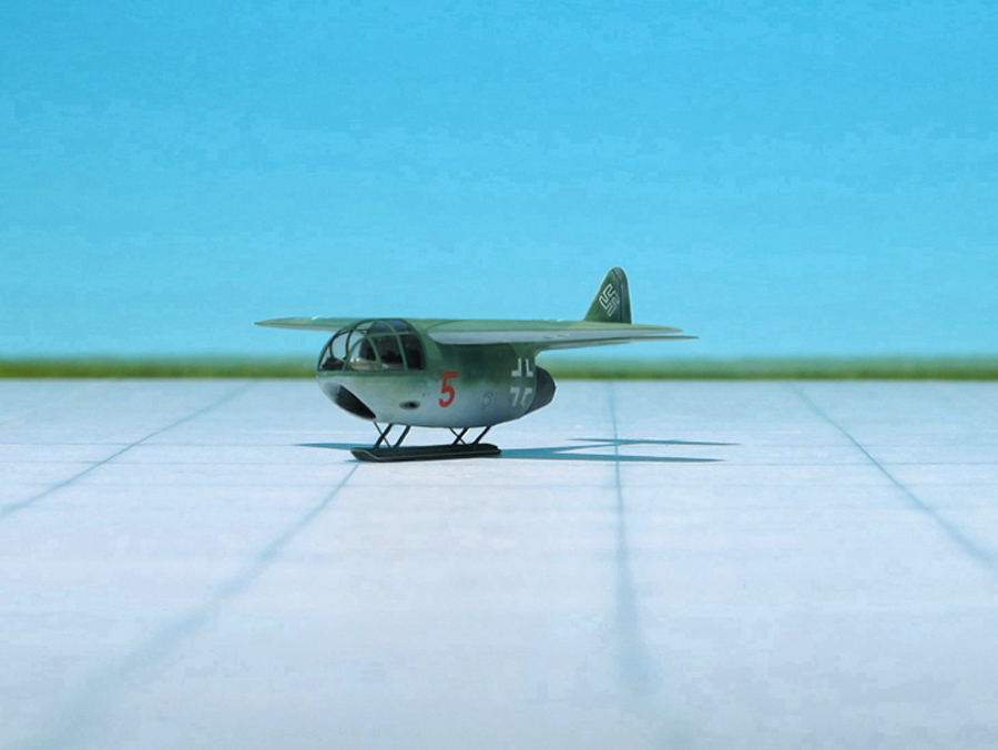
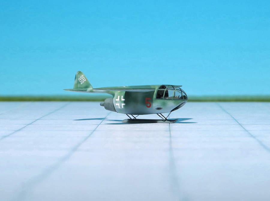
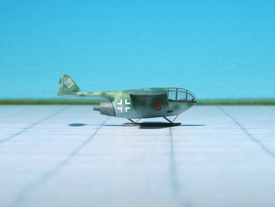
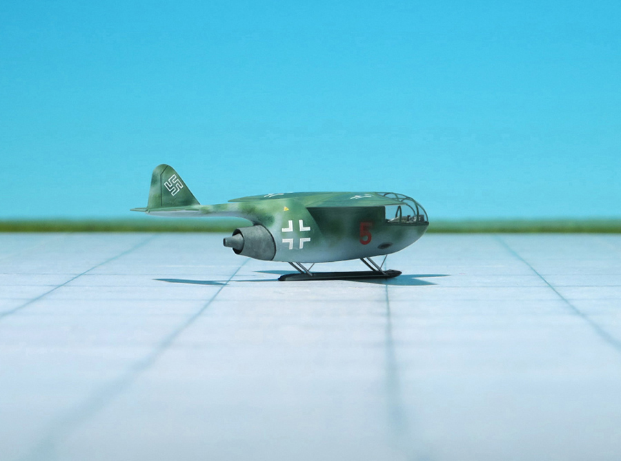
COMMENT: During November 1944, the RLM issued a requirement for the simplest possible type of fighter which could be more rapidly produced than the Heinkel He 162 Salamander (“Volksjäger”), (People-fighter) then being built. The design was not, however, to be a semi-expendable weapon in the manner of the Bachem Ba 349 Natter, because conventional landings and take-offs were to be made. Much had already been done in the Volksjäger competition to simplify airframes, so attention now turned towards simplifying the power unit, though without losing too much in the way of performance. Thus, the power unit was to be a simple pulse-jet as produced by Argus for the Fieseler Fi 103 V 1) flying bomb, a turbojet engine or a liquid-fuelled rocket. The Kleinstjäger or Miniaturjäger was to employ the minimum of strategic materials, dispense with refinements such and electronic equipment and, by virtue of quick production, increase the chances of intercepting the enemy by flying in large numbers.
The problem of supplying all the new pilots was common to both Miniatur- and Volksjäger programmes whichever was adopted. Only three firms, which also participated in the Volksjäger competition, put forward Miniaturjäger projects, Blohm und Voss, Heinkel and Junkers.
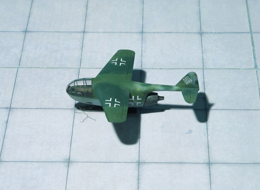
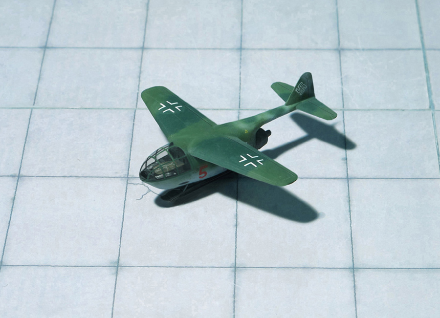
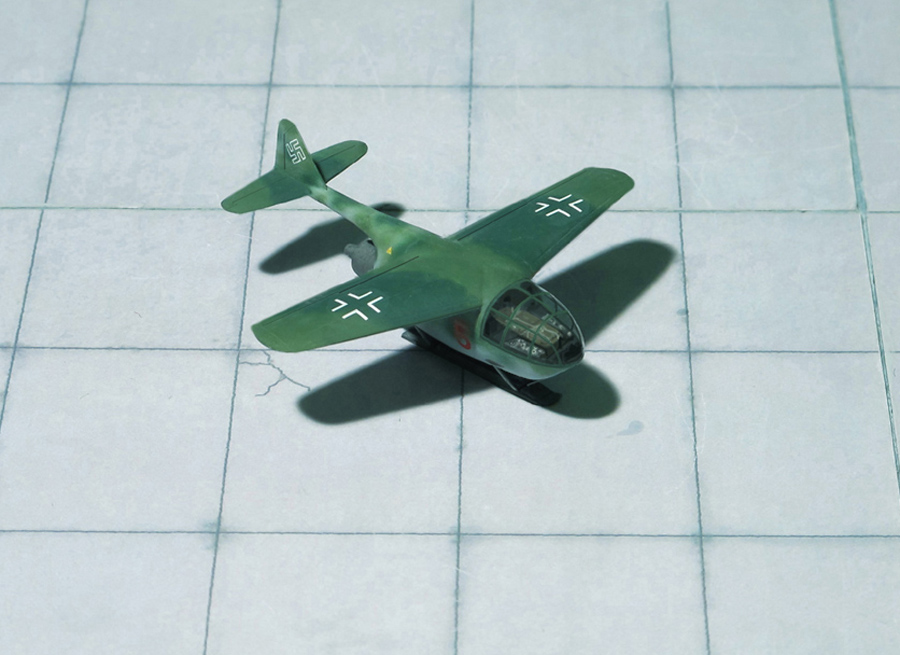
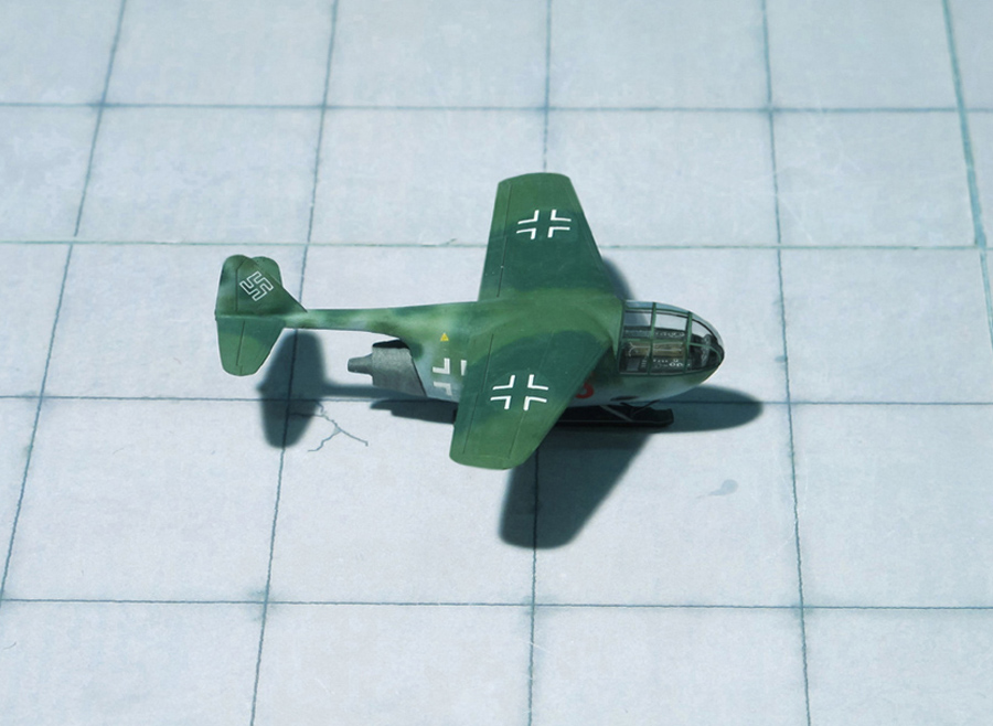
There is also some evidence that the Dornier Company was working on a design for a Miniaturjäger. In literature a three-view thumbnail sketch of a design is known, the in-house project designation is given as Do P…. The little aircraft was to be powered by a BMW 003 turbojet engine. A high-mounted wing with light swept leading edge was envisaged, the air intake was located in the nose with the pilots seat in prone position above it. The turbojet engine was located at the fuselages end, the conventional tail plane was mounted on a boom protruding from the fuselages end. For take-off probably a trolley was used, the landing was provided by means of a retractable skid. No further facts or details are reported. (Ref.: 22 and
J. R. Smith, Antony L. Kay: German Aircraft of the Second World War. Putnam & Company, London, 1972)
Dornier Do P…. “Kleinstjäger”, (Miniature Fighter”)
Dornier Do P…. “Kleinstjäger”, (Miniature Fighter”)
Dornier Do P…. “Kleinstjäger”, (Miniature Fighter”)
Dornier Do P…. “Kleinstjäger”, (Miniature Fighter”)
Dornier Do P…. “Kleinstjäger”, (Miniature Fighter”)
Dornier Do P…. “Kleinstjäger”, (Miniature Fighter”)
Dornier Do P…. “Kleinstjäger”, (Miniature Fighter”)
Dornier Do P…. “Kleinstjäger”, (Miniature Fighter”)
Dornier Do P…. “Kleinstjäger”, (Miniature Fighter”)
Dornier Do P…. “Kleinstjäger”, (Miniature Fighter”)
Dornier Do P…. “Kleinstjäger”, (Miniature Fighter”)
Dornier Do P…. “Kleinstjäger”, (Miniature Fighter”)
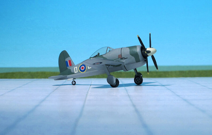
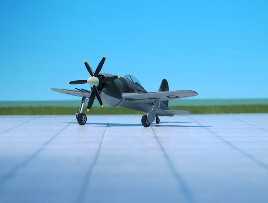
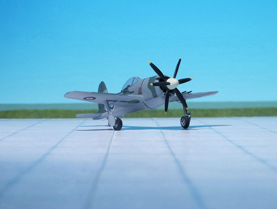
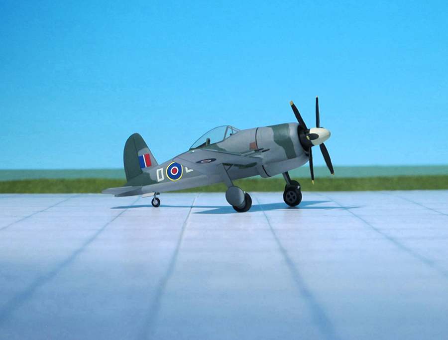
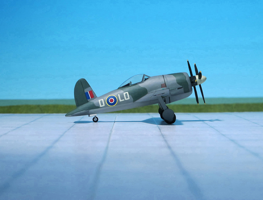
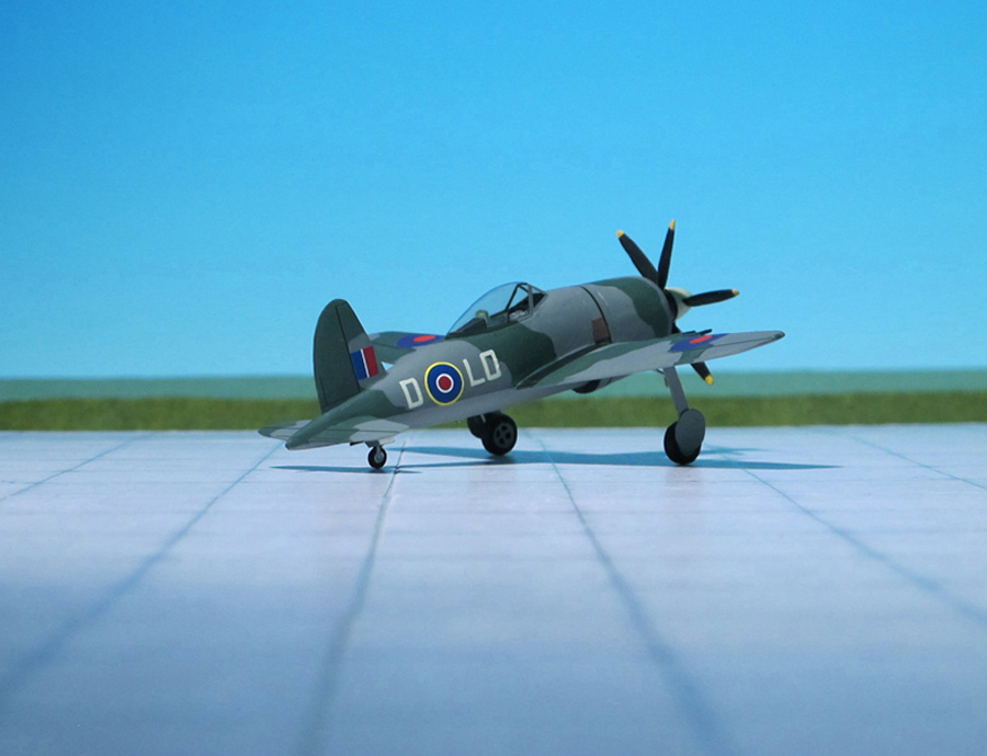
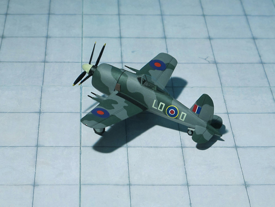
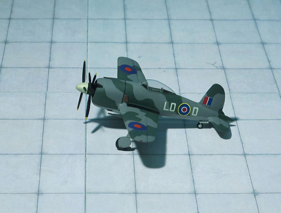
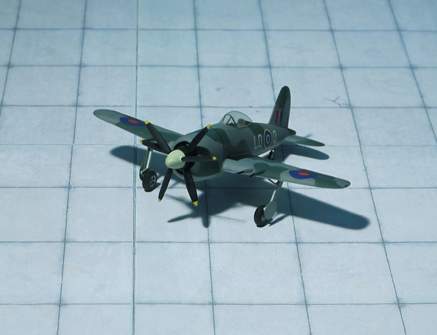
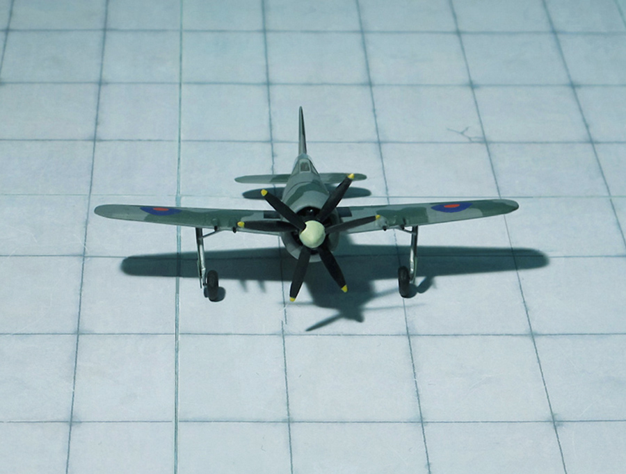
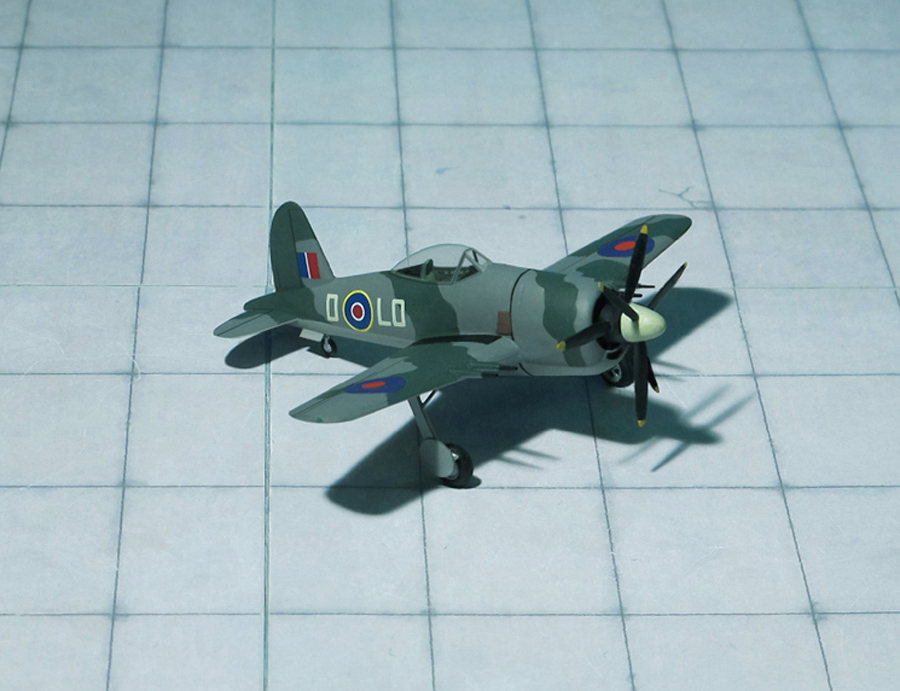
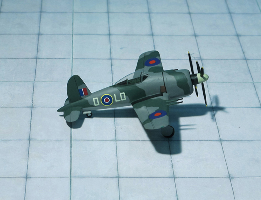
POWER PLANT: One Bristol Centaurus XII radial engine, rated at 2,500 hp
PERFORMANCE: 468 mph at 20,000 ft
COMMENT: In the middle war years it was realized that the current fighter like the Hawker Typhoon were in many respects a bit too large to meet the current requirement for single-seat fighters. Consequently, in September 1942 Specification F.6/42 was issued for a smaller and lighter fighter, the document stating an armament of four 20mm cannon and a speed of 450 mph at 20,000 ft, and this aircraft was to be superior in climb, speed and maneuverability to any fighter that might be developed out of Germany’s superb Focke-Wulf Fw 190. Proposals were forthcoming from Airspeed, Boulton Paul, Folland, Hawker, Supermarine, Vickers and Westland and those from Folland and Hawker were favored, the latter eventually being covered by the new Specification F.2/42 and flown as Hawker Fury.
Follands Fo.117 project generated some attention, particularly its contra-rotating airscrew which was then a new feature in fighter design. The Air Staff had assumed that the reason for having this smaller diameter propeller was to provide a smaller undercarriage and a more compact gun installation, but in fact Folland had used it to raise the wing in relation to the fuselage so that the exhaust and cooling air would be ejected above and below the wing roots, thereby reducing drag. The Fo.117 design was favored by RAE Farnborough but there were doubts about the firm having the ability to develop and manufacture such an advanced aircraft quickly enough.
Follands ability to carry through the project had been thoroughly assessed and it was clear that the company could not do the job by itself, but Folland was prepared to work with another firm. By 29 December several minor changes had been made to the design which had improved the Fo.117’s performance figures and altered the all-up weight to 4,160 kg.
Nevertheless, the Chief of the Air Staff (CAS) felt that the design had some particularly good qualities, especially in its potential maneuverability. Indeed the Folland and Hawker F.6/42 projects were discussed and compared very closely during January 1943. However, in March the Folland Fo.117 was abandoned, in part because the country’s design capacity was already overloaded and there were worries about squandering precious resources by giving a job like this to a company who would probably not have the aircraft ready in a sufficiently short period of time, Folland being relatively new and inexperienced in a job of fighter design. In addition, despite the Fo.117 offering a potentially better performance, Hawker’s own project would be ready much earlier.
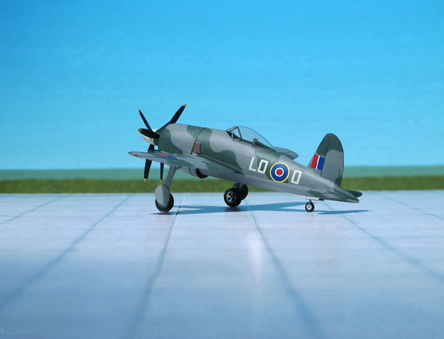
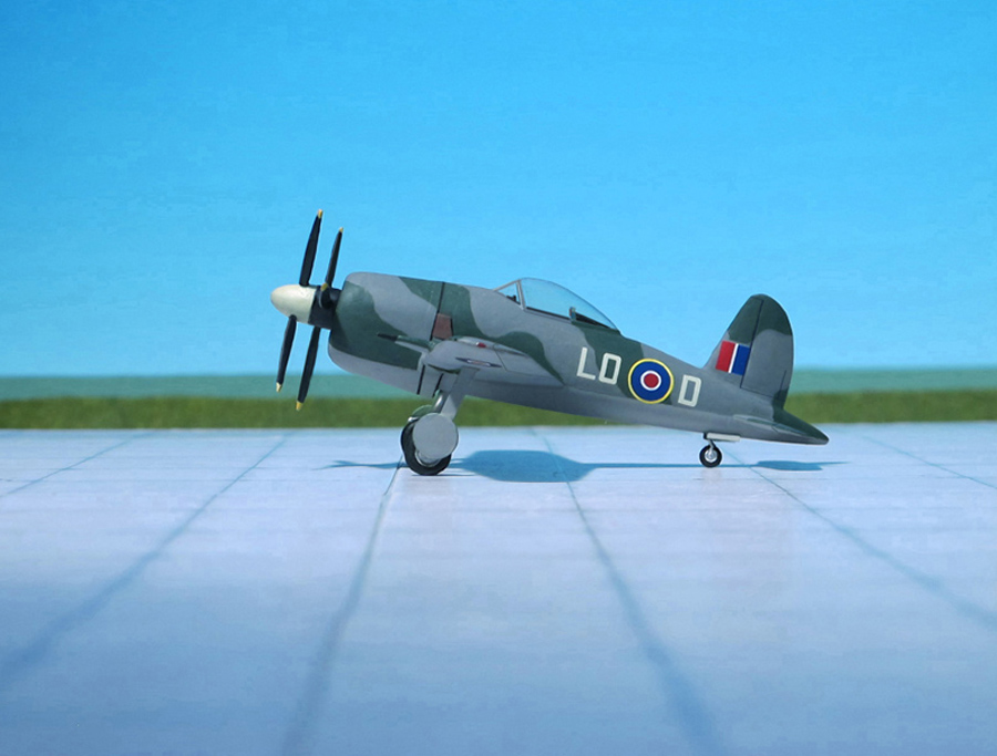
However, later in 1943 the project was revived as Fo.117A, the revised design introducing a laminar flow wing while the 2,500 hp Centaurus XII still had the contra-rotating propeller. Plans were laid down for production aircraft to be produced by English Electric and six prototypes were actually ordered in September 1943 to an updated specification F19/43. However, in the end they were never built and there are no further details available to describe these airplanes and compare them with the original Folland Fo.117.
(Ref.:Tony Buttler: British Experimental Combat Aircraft of World War II, Prototypes, Research Aircraft and Failed Production Designs. Hikoki Publications, Manchester M22 5LH, 2012
Folland Fo.117
Folland Fo.117
Folland Fo.117
Folland Fo.117
Folland Fo.117
Folland Fo.117
Folland Fo.117
Folland Fo.117
Folland Fo.117
Folland Fo.117
Folland Fo.117
Folland Fo.117
Folland Fo.117
Folland Fo.117
Folland Fo.117
Scale 1:72 aircraft models of World War II
Mit der weiteren Nutzung unserer Webseite erklären Sie sich damit einverstanden, dass wir Cookies verwenden um Ihnen die Nutzerfreundlichkeit dieser Webseite zu verbessern. Weitere Informationen zum Datenschutz finden Sie in unserer Datenschutzerklärung.