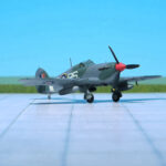
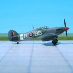
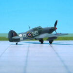
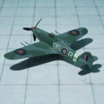
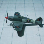
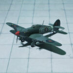
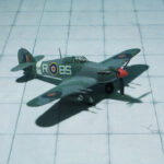
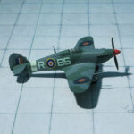
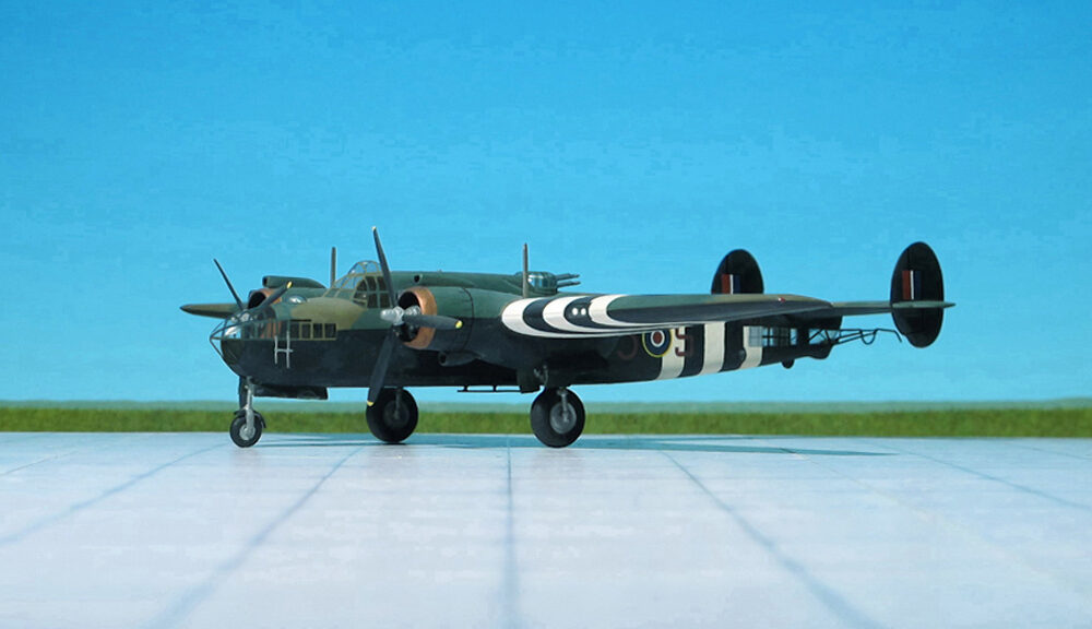
Douglas P-70A, 6th N. F. Sq. (Revell Models)

TYPE: Night intruder and night fighter

ACCOMMODATION: Crew of three

POWER PLANT: Two Wright R-2600-23 Twin Cyclone radial engines, rated at 1,600 hp each

PERFORMANCE: 329 mph at 14,500 ft

COMMENT: The Douglas A-20 Havoc (company designation DB-7) is an American medium bomber, attack aircraft, night intruder, night fighter, and reconnaissance aircraft of WW II.
Designed to meet an Army Air Corps requirement for a bomber, it was ordered by France for their air force before the USAAC decided it would also meet their requirements. French DB-7s were the first to see combat; after the fall of France the bomber, under the servce name Boston continued with the Royal Air Force. From 1941, night fighter and intruder versions were given the service name Havoc. In 1942 USAAF A-20s saw combat in North Africa.
It served with several Allied air forces, principally the United States Army Air Forces (USAAF), the Soviet Air Forces (VVS), Soviet Naval Aviation (AVMF), and the Royal Air Forces (RAF). A total of 7,478 aircraft were built, of which more than a third served with Soviet units.
In most British Commonwealth air forces, the bomber variants were known as Boston, while the night fighter and intruder variants were named Havoc. The exception was the Royal Australian Air Force (RAAF), which used the name Boston for all variants.
The USAAF used the P-70 designation to refer to the night fighter variants.
In October 1940, the USAAC felt a need for long-range fighters more than attack bombers. As a result, sixty of the production run of A-20s were converted to P-70 night fighters, all delivered by September 1942. They were equipped with SCR-540 radar (a copy of the British AI Mk. IV), the glazed nose often being painted black to reduce glare and hide the details of the radar set, and had four 20 mm forward-firing cannon, each provided with 120 rounds, in a tray in the lower part of the bomb bay, while the upper part held an additional fuel tank with a capacity of 250 US gallons . In 1943, 13 A-20Cs and 51 A-20Gs were converted to Douglas P-70A. Differences were to be found in the armament, with the 20mm cannon package replaced by an A-20G gun nose with six .50 caliber guns installed, the SCR-540 radar installation being carried in the bomb bay with the vertical-plane, twin-dipole “arrowhead” transceiving antenna protruding between the nose guns. Further P-70 variants were produced from A-20G and J variants. The singular airframe P-70B-1 (converted from an A-20G) and subsequent P-70B-2s (converted from A-20Gs and Js) had American centimetric radar (SCR-720 or SCR-729) fitted.
The P-70s and P-70As saw combat only in the Pacific during World War II and only with the USAAF. The P-70B-1 and P-70B-2 aircraft never saw combat but served as night fighter aircrew trainers in the US in Florida and later in California. All P-70s were retired from service by 1945 (Ref.: 24).

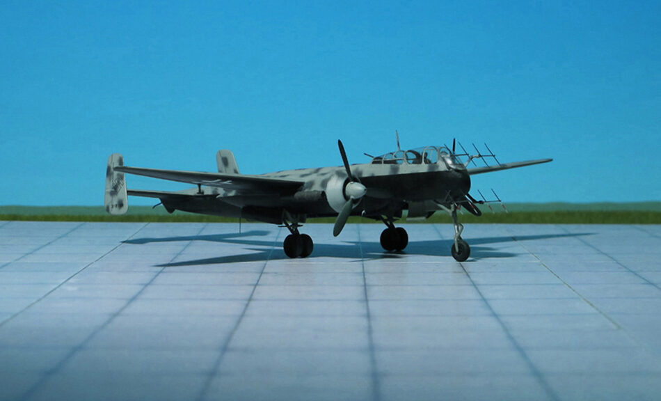
Heinkel He 119 A-0 (V6), (Valom Models)

TYPE: Reconnaissance bomber

ACCOMMODATION: Crew of three

POWER PLANT: One Daimler-Benz DB 606A-2, twenty-four-cylinder liquid-cooled coupled engine, rated at 2,350 hp

PERFORMANCE: 367 mph at 14,755 ft

COMMENT: The Heinkel He 119 was an experimental single-propeller monoplane with two coupled engines, developed in Germany. A private venture by Heinkel to test radical ideas by the Günter brothers, the He 119 was originally intended to act as an unarmed reconnaissance bomber capable of eluding all fighters due to its high performance.
Design was begun in the late summer of 1936. A notable feature of the aircraft was the streamlined fuselage, most likely as an evolutionary descendant of the 1932-vintage Heinkel H 70 record-setting single-engined mailplane design, but without the He 70’s protruding canopy-enclosed crew accommodation existing anywhere along the exterior. Instead, the He 119’s forward fuselage featured an extensively glazed cockpit forming the nose itself, heavily framed with many diagonally braced windows immediately behind the propeller spinner’s rear edge. Two of the three-man crew sat on either side of the driveshaft, which ran aft to a “power system”, a coupled pair of Daimler-Benz DB 601 engines mounted above the wing center-section within the fuselage, mounted together within a common mount (the starboard component engine having a “mirror-image” centrifugal supercharger) with a common gear reduction unit fitted to the front ends of each component engine, forming a drive unit known as the Daimler-Benz DB 606, the first German aircraft to use the “high-power” power plant system meant to provide German aircraft with an aviation power plant design of over 2,000 PS output capability.
The DB 606 engine was installed just behind the aft cockpit wall, near the center of gravity, with an enclosed extension shaft passing through the centerline of the extensively glazed cockpit to drive a large four-blade variable-pitch airscrew in the nose. An evaporative cooling system was used on the first aircraft (V1), with the remaining prototypes receiving a semi-retractable radiator directly below the engine to augment cooling during take-off and climb.
Only eight prototypes were completed and the aircraft did not see production, mainly because of the shortages of DB 601 “component” engines to construct the 1,500 kg “power systems” they formed. The first two prototypes were built as land planes, with retractable landing gear. The third prototype (V3) was constructed as a seaplane with twin floats. This was tested at the “Erprobungsstelle Travemünde” military seaplane test facility on the Baltic coast, and was scrapped in 1942 at Heinkel’s factory airfield in the coastal Rostock-Schmarl community, then known as Marienehe.
On November 1937, the fourth prototype (V4) made a world class-record flight in which it recorded an airspeed of 314 mph, with a payload of 1,000 kg, over a distance of 1,000 km. The four remaining prototypes were completed during the spring and early summer of 1938, the V5 and V6 being A-series production prototypes for the reconnaissance model, and the V7 and V8 being B-series production prototypes for the bomber model.
These four aircraft were three-seaters with a defensive armament of one 7.92 mm MG 15 machine gun in a dorsal position, V7 and V8 having provision for a normal bombload of three 250 kg bombs or maximum bombload of 1,000 kg. V7 and V8 were sold to Japan in May 1940, and extensively studied; the insights thus gained were used in the design of the Yokosuka R2Y1 “Keiun” The remaining prototypes served as engine test-beds, flying with various prototype versions of the DB 606 and DB 610 (twinned Daimler-Benz DB 605) and the experimental DB 613 (twinned Daimler-Benz DB 603).
In 1944, a high-speed bomber development, designed as a private venture by Heinkel to test radical ideas by the Günter brothers, was the Heinkel He 519. It was designed to use the 24-cylinder Daimler-Benz DB 613, but the aircraft remained a concept and was abandoned at the end of the war. (Ref.: 24).

Ilyushin Il-2m3 „Shturmovic“, Plastyk-Micro

TYPE: Ground attack aircraft

ACCOMMODATION: Crew of two

POWER PLANT: One Mikulin AM-38F liquid-cooled engine, rated at 1,720 hp

COMMENT: The Ilyushin Il-2 „Shturmovik“ was a ground attack aircraft produced by the Soviet Union in large numbers during WW II. To Il-2 pilots, the aircraft was simply the diminutive “Ilyusha”, to the soldiers on the ground, it was the “Hunchback”, the “Flying Tank” or the “Flying Infantryman”. With 36,183 units produced during the war it was the most built aircraft forever.
The idea for a Soviet armored ground-attack aircraft dates to the early 1930s.  The Il-2 was designed by Sergey Ilyushin and his team at the Central Design Bureau in 1938. Designated TsKB-55  it was a two-seat aircraft with an armoured shell weighing 700 kg, protecting crew, engine, radiators, and the fuel tank. Standing loaded, the Ilyushin weighed more than 4,700 kg making the armoured shell about 15% of the aircraft’s gross weight. Uniquely for a World War II attack aircraft, and similarly to the forward fuselage design of the World War I-era Imperial German Junkers J.I armored, all-metal biplane, the Il-2’s armor was designed as a load-bearing part of the Ilyushin’s monocoque structure, thus saving considerable weight. The prototype TsKB-55, which first flew on 2 October 1939, won the government competition against the Sukhoi Su-6 and received the VVS (Soviet Air Forces) designation BSh-2 (the BSh stood for “Bronirovani Shturmovik” or armoured ground attack). The prototypes – TsKB-55 and TskB-57 – were built at Moscow plant No 39, at that time the Ilyushin design bureau’s base.
The production aircraft passed State Acceptance Trials in March 1941, and was redesignated Il-2 in April. Deliveries to operational units commenced in May 1941.
The Il-2 was a single-engine, propeller-driven, low-wing monoplane of mixed construction with a crew of two (one in early versions), specially designed for assault operations. Its most notable feature was the inclusion of armor in an airframe load-bearing scheme. Armor plates replaced the frame and paneling throughout the nacelle and middle part of the fuselage, and an armored hull made of riveted homogeneous armor steel secured the aircraft’s engine, cockpit, water and oil radiators, and fuel tanks.
In early 1941, the Il-2 was ordered into production at four factories, but by the time Nazi Germany invaded the Soviet Union on 22 June 1941, only State Aviation Factory 18 at Voronezh and Factory 381 at Leningrad had commenced production, with 249 having been built by the time of the German attack.
Production early in the war was slow because after the German invasion the aircraft factories near Moscow and other major cities in western Russia had to be moved east of the Ural Mountains. Ilyushin and his engineers had time to reconsider production methods, and two months after the move Il-2s were again being produced.
As a result, “the production of Shturmoviks rapidly gained speed. Stalin’s notion of the Il-2 being ‘like bread’ to the Red Army took hold in Ilyushin’s aircraft plants and the army soon had their Shturmoviks available in quantity.”
The first use in action of the Il-2 was with the 4th ShAP (Ground Attack Regiment) over the Berezina River days after German invasion began. The aircraft was so new that the pilots had no training in flight characteristics or tactics, and the ground crew no training in servicing or re-arming. The training received enabled the pilots only to take-off and land; none of the pilots had fired the armament, let alone learned tactics. There were 249 Il-2s available on 22 June 1941. In the first three days, 4th ShAP had lost 10 Il-2s to enemy action, a further 19 were lost to other causes, and 20 pilots were killed. By 10 July, 4th ShAP was down to 10 aircraft from a strength of 65.
Tactics improved as Soviet aircrews became used to the Il-2’s strengths. Instead of a low horizontal straight approach at 50 metres altitude, the target was usually kept to the pilot’s left and a turn and shallow dive of 30 degrees was used, using an echeloned assault by four to twelve aircraft at a time. Although the Il-2’s RS-82 and RS-132 rockets could destroy armored vehicles with a single hit, they were so inaccurate that experienced Il-2 pilots mainly used the cannon.
The main problem with the Il-2 was the inaccuracy of its attacks. Towards the end of war, the Soviets were able to concentrate large numbers of Shturmoviks to support their main offensives. The effect, however, was often more psychological than actual physical destruction of targets, particularly against dug-in and armored targets. The heavy armor of the Il-2 also meant that it would typically carry only comparatively light bomb-loads, which together with the poor accuracy of its attacks made it a far less deadly attack aircraft than contemporary Allied fighter-bombers such as the Republic P-47 „Thunderbolt“ and Hawker „Typhoon“. The rocket projectiles especially were not effective, even the larger RS-132 (of which four were carried) having a warhead with only 0.9 kg of explosives, which compared poorly with the P-47’s typical load of ten 13 cm HVAR‘s, each having a 21 kg warhead, or the 8 to 12 27 kg warheads of the Hawker „Typhoon’s“ RP-3 rockets.
Heavy losses to enemy fighters forced the reintroduction of a rear gunner; early Il-2s were field modified by cutting a hole in the fuselage behind the cockpit for a gunner sitting on a canvas sling armed with a 12.7 mm UBT machine gun in an improvised mounting. The semi-turret gun mount allowed the machine gun to be fired at angles of up to 35° upwards, 35° to starboard and 15° to port. Tests showed that maximum speed decreased by between 10 and 20 km/h and that the two-seater was more difficult to handle because the center of gravity was shifted backwards. At the beginning of March 1942, a production two-seat Il-2 with the new gunner’s cockpit began manufacturer tests. The second cockpit and armament increased all-up weight by 170 kg so the flaps were allowed to be deployed at an angle of 17° to avoid an over-long takeoff run. The new variant had a lengthened fuselage compartment with an extended canopy offering some protection from the elements. Unlike the well-armoured cockpit of the pilot compartment with steel plating up to 12 mm thick behind, beneath and on both sides as well as up to 65 mm thick glass sections, the rear gunner was provided with 6 mm thick armour, effective only against rifle-calibre rounds.
While the Il-2 was a deadly air-to-ground weapon, and even a fairly effective interceptor against slow bombers and transport aircraft, heavy losses resulted from its vulnerability to fighter attack. Losses were very high, the highest of all types of Soviet aircraft, though given the numbers in service this is only to be expected. „Shturmovik“ losses (including Il-10 type), in 1941–1945, were of 10,762 aircraft. The main defensive tactic was flying low and power down as the fighters closed in to let the fighter overshoot and fly into the Il-2’s firing range (Ref.: 24).

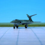
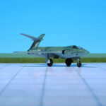
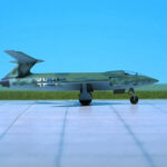
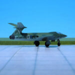
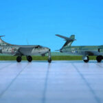
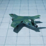
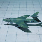
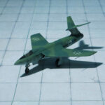
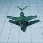
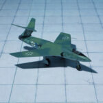
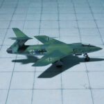
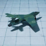
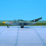
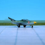
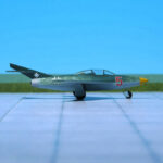
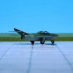
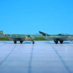
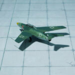
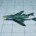
Blohm & Voss Ae 607 (RS Models, Resin)

TYPE: Experimental flying wing aircraft

ACCOMMODATION: Pilot only

POWER PLANT: One Heinkel-Hirth HeS 011 turbojet, rated at 1,200 kp thrust

PERFORMANCE: Unknown

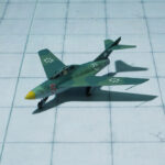
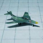
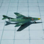
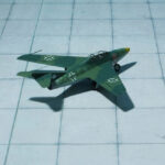
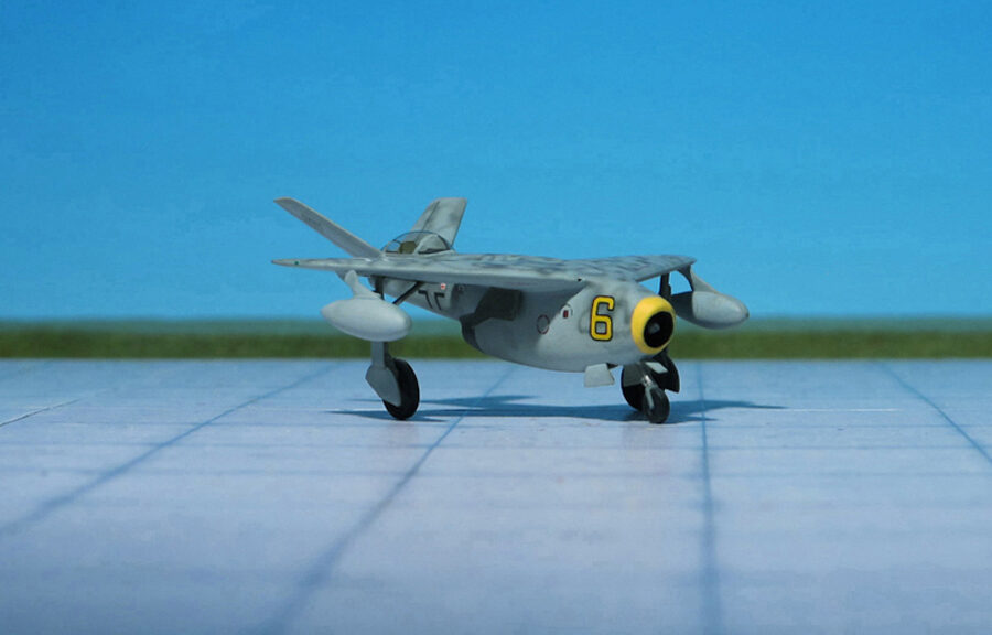
COMMENT: The Blohm & Voss Ae 607 was a turbojet-powered flying wing design drawn up by Blohm & Voss in 1945. Very little is known about it and its existence was only confirmed end of the last century.
Early in 1945, a Blohm & Voss aircraft designer called Thieme began work on Drawing Number Ae 607 within the standard drawing numbering system at B&V and labelled it „Nurflügel-TL-Jäger“ („All-wing jet fighter“). His design for a jet fighter was radically different from anything that B&V had done before: A flying wing, it approximated to a 45° delta planform.
An all-wing design, the centre section has a V-shaped lower profile deepening its keel and is sharply tapered both front and rear, while the outer sections are sharply swept at approximately 45° and tapered, giving the leading edge a sweep greater than 45° and the trailing edge an M-shaped outline from above. The wing tips are turned down, giving them a slight anhedral.
A turbojet engine duct runs down the centre, with the Heinkel-Hirth HeS 011 engine installed towards the rear. A small tail fin is placed above the jet exhaust duct, while the pilot’s cockpit is set just in front of the engine, but still well aft, and is offset to one side to give the pilot room alongside the intake duct. It is covered by a teardrop canopy. Two small, low aspect ratio and untapered canard foreplanes sweep forward from either side of the nose intake.
The undercarriage comprises main wheels retracting outwards and twin tailwheels retracting on either side of the engine exhaust duct. On the ground, it sits with a marked nose-up attitude presumably to keep the air intake well away from any surface debris while take-off. Estimated performance as well as it’s conceptual formulation is unknown. The Blohm & Voss Ae 607 „Nurflügel-TL-Jäger“ never received a „P“ number (Project number) and was probably only intended to showcase ideas for solving particular problems facing designers when designing on a layout for fighters. The authenticity of the „Nurflügel-TL-Jäger“ has been questioned for years but, oddly enough, it has proven to be an entirely genuine wartime design (Ref.: 24).

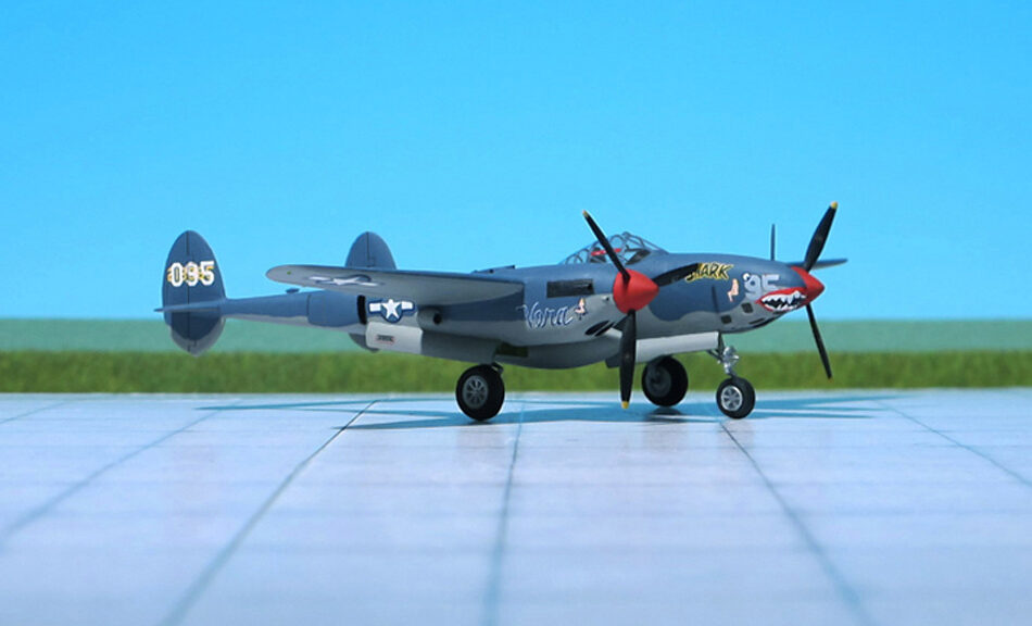
Lockheed P-38F “Lightning” ,39th Sqd, 35th FG, (Hasegawa)

TYPE: Fighter, fighter bomber

ACCOMMODATION: Pilot only

POWER PLANT: Two Allison V-1710-49/53 liquid-cooled engines, rated at 1,225 hp each

PERFORMANCE: 390 mph at 25,000 ft

COMMENT: The Lockheed P-38 Lightning was an American piston-engined fighter aircraft of WW II. Developed for the United States Army Ai Corps, the P-38 had distinctive twin booms and a central nacelle containing the cockpit and armament. Allied propaganda claimed it had been nicknamed the fork-tailed devil (Gabelschwanz-Teufel“) by the Luftwaffe and “two planes, one pilot” by the Japanese. Along with its use as a general fighter, the P-38 was utilized in various aerial combat roles including as a highly effective fighter-bomber, a night-fighter, and as a long-range escort fighter when equipped with drop tanks. The P-38 was also used as a bomber-pathfinder, guiding streams of medium and heavy bomber; or even other P-38s, equipped with bombs, to their targets. Used in the aerial reconnaissance role, the P-38 would account for 90 percent of the aerial film captured over Europe.
The P-38 was used most successfully in the Pacific Theater of Operations (PTO) and was the primary long-range fighter of Unites States Army Air Forces until the introduction of large numbers of North American P-51D „Mustang“ toward the end of the war.
Lockheed designed the Model 22 in response to a February 1937 specification from the United States Arma Air Corps (USAAC). Circular Proposal X-608 was a set of aircraft performance goals for a twin-engine, high-altitude aircraft having the tactical mission of interception and attack of hostile aircraft at high altitude.  The Lockheed design team chose twin booms to accommodate the tail assembly, twin engines, and turbo-superchargers, with a central nacelle for the pilot and armament.
The Lockheed design incorporated tricycle undercarriage and a bubble canopy, and featured two 1,000 hp turbosupercharged 12-cylinder Allison V-1710 engines fitted with counter rotating propellers to eliminate the effect of engine torque, with the turbochargers positioned behind the engines, the exhaust side of the units exposed along the dorsal surfaces of the booms. The aircraft was the first American fighter to make extensive use of stainless steel and smooth, flush-riveted butt-jointed aluminum skin panels It was also the first military airplane to fly faster than 400 mph in level flight.
Lockheed won the competition on June 1937 with its Model 22 and was contracted to build a prototype officially designated XP-38.  Construction began in July 1938, and the XP-38 first flew on 27 January 1939. After speed testing the Air Corps ordered 13 YP-38s on April 1939, these few “hand made” YP-38’s were used as trainers and test aircraft.
Delivered and accepted production variants began with the P-38D model but the first combat-capable Lightning, as the aircraft was officially named by the USAAC by adopting the British service name, was the P-38E and its photo-reconnaissance variant the F-4
The first P-38E rolled out of the factory in October 1941. Because of the versatility, redundant engines, and especially high speed and high altitude characteristics of the aircraft, as with later variants over a hundred P-38Es were completed in the factory or converted in the field to a photoreconnaissance variant, the F-4, in which the guns were replaced by four cameras. Most of these early reconnaissance Lightnings were retained stateside for training, but the F-4 was the first Lightning to be used in action in April 1942.
After 210 P-38Es were built, they were followed, starting in February 1942, by the P-38F, the first truly operational Lightning. It incorporated racks inboard of the engines for fuel tanks or a total of 910 kg of bombs. 527 machines of this subtype were buit, including several variants. Lightnings of this type took part in their first large-scale operations during the North-African campaign, in November 1942, where mixed success was encountered. The twin engines restricted manoeuverability to some extent and it was unique among fightersof WW II in employing a wheel control instead of a conventional stick, a feature which may also have resulted in reduced ease of manoeuvre. Nevertheless, it proved an effective bomber destoyer and had a sensational zoom climb that could rarely be matched.
The Lockheed P-38F Lightning had also entered service in the Pacific area. Technical difficulties associated with intercooler operations in tropical conditions prevented the Lightning from entering service until the end of 1942, however, the first major engagement with Japanese aircraft occuring on December, when the 39th Fighter Squadron claimed 15 destroyed without loss (the model shown here is a P-38F of the 39th Fighter Squadron, 35th Fighter Group).
During production a continous series of improvements were being developed by Lockheed, some of which remained experimental but others being adopted for production. Among the most important in the latter category were long-range drop tanks and manoeuvring flaps. In early 1942, all P-38 carried the same long-range 75-US gal drop tanks as the Bell P-39 Aircobra and Curtiss P-40 Warhawk, one each side between the fuselage and nacelles. But Lockheed soon developed its own 150-US gal tank, and eventually 300-US gal versions, of laminar flow design. Stressing the wing section two such tanks could be carried by all variants  from the P-38F onwards. To demonstrate the capability oft he Lightning with drop tanks, a P-38F was used late in 1942, to make an endurance flight lasting over 13 hrs and covering 4.677 km, with enough fuel remaining for more than 161 km. Thus, Lightning’s ability to fly long ranges, carrying two drop tanks, now proved especially useful and the P-38 became the most-preferred fighter type operating in the Pacific area.
After production of 2,410 P-38F, -G and –H and corresponding reconnaissance variants the production switched over to the most built Lockheed P-38J and –L Lightnings (Ref.: 3, 9, 24).

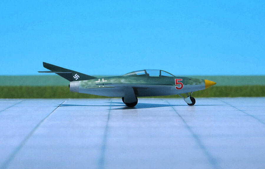
Heinkel He P. 1078C (Frank Airmodel, Resin)

TYPE: Interceptor

ACCOMMODATION: Pilot only

POWER PLANT: One Heinkel/Hirth HeS 011 turbojet engine, rated at 1,200 kp thrust

PERFORMANCE: 480 mph at 32,800 ft

COMMENT: The Heinkel He P.1078 was a single-seat interceptor developed for the Luftwaffe by Heinkel aircraft manufacturing company under the  „Jägernotprogramm“ (Emergency Fighter Programm) during the closing stage of the Third Reich.
Germany’s Emergency Fighter Program was enacted in the middle of July in 1944 in response to the Allied bombing offensive taking out critical German war-making capabilities. The new aircraft was intended to have superior performance in order to deal with the expected high altitude threats such as the Boeing B-29 Superfortress, but only had a 30-minute endurance figure.
The high-altitude fighter designs brought forward by other German aircraft makers were the Messerschmitt Me P.1101, Focke-Wulf Ta 183 „Huckebein“, Blohm & Voss Bv P.212, and Junkers EF 128.
The Heinkel Company was a competitor, too, and offered ist He P.1078 project in three quite different variants. All of them were a single-seat fighters with polyhedral swept wings. The wings were swept back at 40 degrees and included wood in their construction. All of the projected aircraft had the wing tips angled downwards and all of them would be powered by a single Heinkel/Hirth HeS 011 turbojet.
The Heinkel He P.1078A was a turbojet-powered interceptor. It was the most conventional-looking of the three designs submitted for it was the only one having a tail. Its armament was two MK 108 cannons, as in the following two variants.
The Heinkel He P.1078B was a tailles asymmetric jet-powered interceptor with a short fuselage in which the air intake of the engine was located in the middle between two gondolas. The cockpit was located on the gondola of the left side, while the right side gondola contained the front undercarriage leg and cannon armament.
Finally the Heinkel He P.1078C was a tailless interceptor project similar to the He P.1078B but with a single short fuselage. Both the He P.1078B and He P.1078C had wing tips angled downwards at a more pronounced angle than the He P.1078A.
To keep production costs down and expedite mass production, the Heinkel He P.1078C design was relatively simple in nature, utilizing wood wherever possible. The metal fuselage sported a length no longer than 17 feet and contained the armored cockpit, armament and relatively large single engine fitting, fuel was to be housed in the wings. Wingspan was just under 30 feet and the design as a whole just topped 7 feet, 8 inches in height. The armament would have consisted of two MK 108 cannons fitted to either side of the nose section. The nose section itself was rather short and acted as the air intake to aspirate the turbojet engine buried further aft in the design. The opening was rectangular in nature and conformed well to the fuselage’s square appearance when viewed in the forward profile. The engine exhausted at the rear through a conventional exhaust ring. The cockpit was held well-forward in the design with the pilot seated under a small canopy allowing for limited viewing ahead and to the sides (the rear was obstructed by way of a short fuselage spine). The undercarriage was fully retractable and would have consisted of three landing gear legs: two main legs at amidships and a nose landing gear leg – all were single-wheeled installations. When at rest, this arrangement would have given the He P.0178C a distinct “nose-up” appearance, in effect perhaps promoting quicker take-offs with the increased wing drag at speed. Since the turbojet-powered fighter would have been operating at high altitudes, the cockpit was to be fully pressurized and equipped withan ejection seat.
Perhaps the most identifiable portion of the He P.1078Cs design was its wings. The assemblies were fitted high against the fuselage sides and extensively swept rearwards. Each wing was cranked upwards from fuselage centerline up to roughly three-quarters out and then capped with a short wing piece cranked sharply downwards. The reason for this design was largely related to aerodynamic principles that were still being researched at the time and the result was to have combated stress effects on the wings at high speeds. Ernst Heinkel was convinced of their ability to provide for increased maneuvering and agility during dogfights. It bears note that there were no horizontal tailplanes in the Heinkel design and the entire internal fuel load for the thirsty turbojet engine was to be stored across both of the wings. However, the wings were not armored which unduly would have exposed them to enemy fire even of the slightest degree.
After being subject to severe criticism, the project was cancelled by Heinkel at the end of February 1945 (Ref: 17, 22, 24).

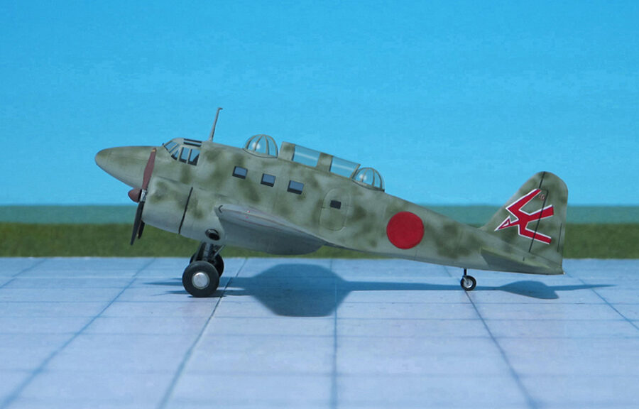
Kugisho (Yokosuka) R2Y2 “Keiun-Kai”(Airmodel, Resin)

TYPE: Fast attack bomber

ACCOMMODATION: Crew of two

POWER PLANT: Two Mitsubishi Ne 330 axial-flow turbojet engines, rated at 1,320 kp each

PERFORMANCE: 495 mph (estimated)

COMMENT: In late 1944, Kugisho (a WW II acronym for Dai-Ichi Kaigun Koku Gijitsusho, First Naval Air Technical Arsenal. Kugisho was based at Yokosuka, hence the type is often incorrectly designated Yokosuka) approached the Imperial Japanese Navy (IJN) and informed them that the Yokosuka R2Y1 Keiun‘s airframe was readily adaptable to other roles, including that of a fast attack bomber. To heighten the interest, it was proposed that the Ha-70 10 engine be replaced with two Mitsubishi Ne330 axial flow turbojets, each of the engines being slung under the wings in nacelles. The fuselage space vacated by the Aichi engine would be replaced with fuel tanks. For weapons, the aircraft would carry one 1,800kg bomb and have a cannon armament in the nose. With the introduction of the Ne330 engines, the maximum speed was expected to be 495mph, superior to the projected 447 mph top speed of the Aichi engine model. With these advantages in mind, the IJN approved that work should begin on designing the R2Y2, the turbojet powered “Keiun” which was sometimes referred to as the “Keiun-Kai”, as well as permitting the R2Y1 to be completed as an airframe demonstrator to test the handling characteristics.
Even before the destruction of the first R2Y1, a second example was being constructed and design work for the R2Y2 was underway.
Contemporary sources show no less than four versions for how the R2Y2 may ultimately have appeared. The first version had the Ne330 engines in underwing nacelles. The second version showed the two engines buried within the fuselage with wing root air intakes and narrow jet nozzles. The third version removed the wing intakes and replaced them with a nose intake, but it retained the narrow nozzles. Finally, the fourth version was similar to the third except the engine nozzles were larger.
The first design is considered by most to be the initial R2Y2 concept while the other three are subject to debate. In part, this is due to the fact that the Japanese had very little time to explore various installations of turbojets in airframes. The easiest means to place turbojets on aircraft was by using nacelles and this was seen in the Nakajima “Kitsuka”, Nakajima Ki-201 “Karyu” and proposed Kugisho “Tenga” and Kawanishi K-200.
Even the Germans with their turbojet experience did not fully understand the effects of a long nose intake feeding a high performance jet buried in a combat fighter’s fuselage. Messerschmitt, when they began to study how to start the Messerschmitt Me P.1101 Vl second generation jet fighter, catalogued the obstacles that needed to be overcome. They included the effects of engine operation on the fuselage integrity, ensuring the nose intake was properly positioned and shaped for maximum airflow, making sure the intake tube was made as smooth as possible to minimize air restrictions, how to protect the rear of the aircraft from the heat generated by the exhaust thrust, the effects of reduced airflow on thrust due to flight angles and more. The Germanswere at least able to devote some time to investigating these problems and providing promising solutions to them.
This was time however, that the Japanese simply did not have. Up until the construction of the and the planned Focke-Wulf Ta 183, all of the War time jet designs flown by the Luftwaffe had nacelle mounted turbojets, e.g. Messerschmitt Me 262. The Japanese may not have been made fully privy to the latest German jet engine technology as it pertained to long intakes before the war ended.
It is within reason to suggest that the R2Y2 with the wing root intakes could have been under consideration since it would be a logical development, especially since such intake arrangements were not entirely new. The third and fourth designs may or may not have been post-war conjecture.
Unfortunately for Kugisho and the IJN, the R2Y2 would never be brought to full production. With the end of the war, the second R2Y1 prototype remained incomplete and the R2Y2 would forever remain a design board aircraft

(Ref.: Dyer III, Edwin M.: Japanese Secret Projects, Experimental Aircraft of the IJA and IJN 1939-1945, Midland Publishing, Hersham, U.K., 2010).

Focke-Wulf Fighter Project II (MP-Models)

TYPE: Fighter, interceptor

ACCOMMODATION: Pilot only

POWER PLANT: One Junkers Jumo 004B turbojet engine, rated at 950 kp thrust

PERFORMANCE: 541 mph at 13,130 ft

COMMENT: The earliest known Focke-Wulf attempt at a single-turbojet fighter, shown in a drawing dated November 1942, the Focke-Wulf Fw 190TL, had involved simply bolting a very basic in-house designed turbojet Fw T.1 to the front of an operational Fw 190.
On January 1943, company aerodynamicist J. C. Rotta offered a report entitled “Fundamentals For The Design of a Turbojet Fighter” which looked at how a large turbojet fighter ought to be, what sort of shape and layout would be best, what turbojet engines could be fitted and how, what the advantages and disadvantages of piston engines and turbojet engines were and what aerodynamic issues were.
To illustrate his points, Rotta came up with a trio of remarkably foresighted designs:

Fighter with turbojet engine BMW 003, P 3302 Design 1,
Fighter with turbojet engine BMW 003, P 3302 Design2, and
Fighter with turbojet engine Junkers Jumo 004.

Each of the three designs had its turbojet engine mounted on its back, just as the Heinkel He 162 would be configured 20 months later. The first and third designs also had forward-swept wings and backward-swept V-tails. The second BMW powered P 3302 design had unswept wings and an unswept V-tail.
However, Focke-Wulf’s design team seem to have completely ignored Rotta’s ideas when they actually started work on a series of single-seat, single-engine turbojet fighters. A report from August 1944 charts the team’s progress through seven different designs.
The first of these, dated March, 1943, was a tail-sitter based on a Fw 190 but with the cockpit relocated to the nose in place of the familiar BMW 801 piston engine, with the turbojet positioned directly below. But with this arrangement no satisfactory rolling properties were to be expected and there was also the risk of burning the airfield surface.
The second design from June, 1943, seems th have been more highly regarded and had its own separate “Baubeschreibung” (Construction description) number, the closest thing Focke-Wulf had to a “P” designation.
The wing was mounted mid-fuselage and had a slight sweep on the leading edge and straight trailing edges, the tailplane was similar to the Fw 190. The design had a tricycle undercarriage and a Junkers Jumo 004B turbojet engine was positioned more centrally under the fuselage. The cockpit was heavily protected by armor of varying thicknesses. Armament was to be two MK 108 (70 rounds each) or MK 103 30mm cannon in the fuselage nose and two MG 151/20 20mm cannon (175 rounds each) in the wing roots.
The main advantage of positioning the turbojet engine under the fuselage was to facilitate maintenance, but there were several bigger disadvantages to this design, such as the nose wheel blocking the intake on take-off and landing, objects being sucked into the air intake since it was so close to the ground. and the damage or destruction of the turbojet engine in case of a belly landing.
Finally, this design was rejected.
As far as the other five different designs are concerned.  Two oft them were basis for the later Focke-Wulf twin-boom Fighter Projekt VIII „Flitzer“ („Streaker“) and  swept-wing, high-mounted tailplane featured Focke-Wulf  interceptor Ta 183 „Huckebein“ (Ref: 17, Uhr, D. and D. Sharp: „Luftwaffe:Secret Projects Profile“, Mortons Media Group Ltd., Horncastle, U.K., 2018).

Martin XB-48 (Anigrand Models, Resin)

TYPE: Medium turbojet-driven bomber

ACCOMMODATION: Crew of three

POWER PLANT:  Six General Electric J35 turbojet engines, rated at 1.734 kp each

PERFORMANCE: 523 mph at 35,000 ft

COMMENT: The Martin XB-48 was an American medium jet bomber developed in the mid-1940s. It competed with the Boeing B-47 “Stratojet”, which proved to be a superior design, and was largely considered as a backup plan in case the B-47 ran into development problems. It never saw production or active duty, and only two prototypes were built.
In 1944, the U.S. War Department was aware of aviation advances in Germany and issued a requirement for a range of designs for medium bombers weighing from 80,000 lb (36,287 kg) to more than 200,000 lb (90,718 kg). Other designs resulting from this competition, sometimes named “the class of ’45”, included the North American XB-45 and the Convair XB-46. Production orders finally went to the North American B-45 “Tornado”, and even this airplane served only for a couple of years before again being replaced by the much more modern Boeing B-47 “Stratojet”, although the B-45 had enough “utility” built in to maintain a niche as a reconnaissance aircraft.
In retrospect, the “class of ’45” were transitional aircraft, combining the power of turbojets with the aeronautical knowledge of World War II. The XB-48 was no exception, as its round fuselage and unswept wings showed a distinct influence of Martin’s B-26 “Marauder” medium bomber. Still, where the B-26 had enough thrust with two massive 18-cylinder radial engines, the XB-48 needed no less than six of the new jet engines.
Although the pictures make it look as if the aircraft had three engine nacelles under each wing, the jet engines were actually clustered in a pair of flat three-engined nacelles with an intricate system of air ducts between the engines, intended to facilitate cooling. At the time of the XB-48’s design, jet propulsion was still in its infancy.
The XB-48 was the first aircraft designed with bicycle-type tandem landing gear, which had previously been tested on a modified B-26. The wing airfoil was too thin to house conventional landing gear mechanisms. The main landing gear was in the fuselage and small outriggers located on each wing were used to balance the aircraft.
The XB-48 made its first flight on 22 June 1947, a 37-minute, 117 km hop from Martin’s Baltimore, Maryland plant to NAS Patuxent River, Maryland, but blew all four tires on its fore-and-aft mounted undercarriage on landing when the test pilot applied heavy pressure to the specially-designed, but very slow to respond, insensitive air-braking lever.
In 1948 the Martin XB-48 program was cancelled (Ref.: 24).

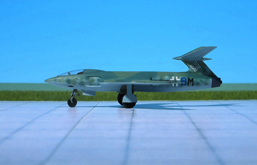
Dornier Do 335A-6 (Dragon Models)

TYPE: Two-seat all weather and night interceptor

ACCOMMODATION: Pilot and radar operator

POWER PLANT: Two Daimler-Benz DB 603A-2, rated at 1,726 hp each

PERFORMANCE: 400 mph at 17,400 ft

COMMENT: The Dornier Do 335 “Pfeil” (“Arrow”) was a WW II heavy fighter built by the Dornier Company. The Do 335s performance was much better than other twin-engine designs due to its unique push-pull configuration and the lower aerodynamic drag of the in-line alignment of the two engines. It was Germany’s Luftwaffe fastest piston-engine aircraft of World War II. The Luftwaffe was desperate to get the design into operational use, but delays in engine deliveries meant that only a handful were delivered before the war ended.
In early 1944 the Do 335 was scheduled to begin mass construction, with the initial order of 120 preproduction aircraft to be manufactured by DWF (Dornier-Werke Friedrichshafen) to be completed no later than March 1946. This number included a number of bombers, destroyers (heavy fighters), and several yet to be developed variants. At the same time, DWM (Dornier-Werke München) was scheduled to build over 2000 Do 335s in various models, due for delivery in March 1946 as well.
While the Dornier Do 335A-0 assembly line at Oberpfaffenhofen was struggling to overcome delays in deliveries of power plants, airscrews, radio equipment and sub-contracted components and assemblies, a number of “Versuchs” (Test) machines for other “Pfeil” subtypes joined the test programme, these including the first two seat models, the Do 335A-6 bad-weather and night interceptor and the Do 335A-12 trainer..
The Dornier Do 335 V10 was the first prototype for the Do 335A-6 radar-equipped two set all weather and night interceptor in which a second cockpit for the radar operator was inserted aft and above the normal cockpit. In order to provide space for the additional cockpit the fuel tankage was drastically revised, the weapon bay being deleted and its space utilized for fuel, fuselage tankage being increased substantially. Cannon armament remained unchanged, but a FuG 101a radio altimeter was
introduced together with FuG 217J-2 “Neptun” intercept radar with wing-mounted antennae. Exhaust flame damping tubes for the fore and aft engines added their measure of drag to that provides by the second cockpit and the radar antennae, and normal loaded weight increased by app. 500 kg. Performance accordingly fell by 10 per cent, but whereas the Do 335 V10 had Daimler-Benz DB 603A-2 engines, the production Do 335 A-6 was intended to have DB 603E engines with provision for methanol-water injection (MW 50) for power boosting below the rated altitude of power plants. Provision was to be made in the wings for two MW 50 tanks, power being boosted to 2,400 hp at sea level per engine.
Production of the Dornier Do 335A-6 night and all-weather fighter had been transferred to the Heinkel factory at Vienna, but despite high priority allocated to the program, circumstances prevented the necessary jigs and tools being assembled (Ref: 7, 12).