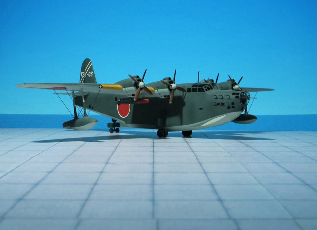
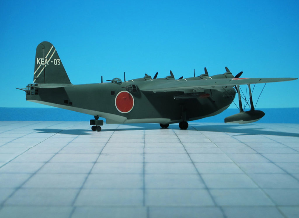
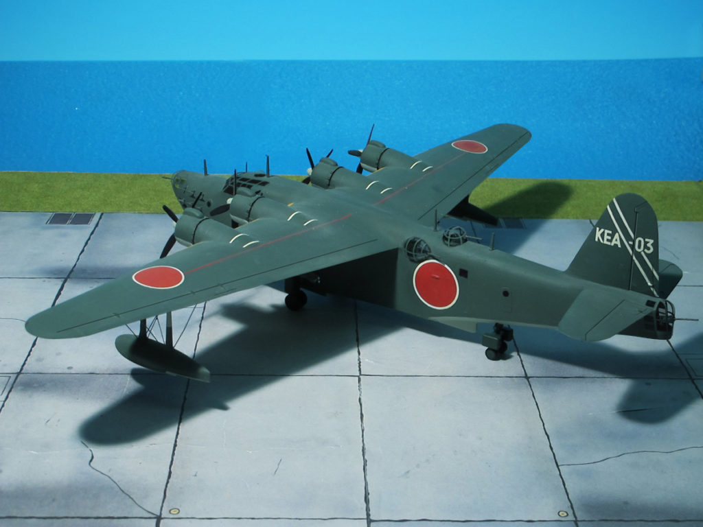
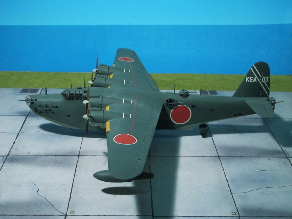
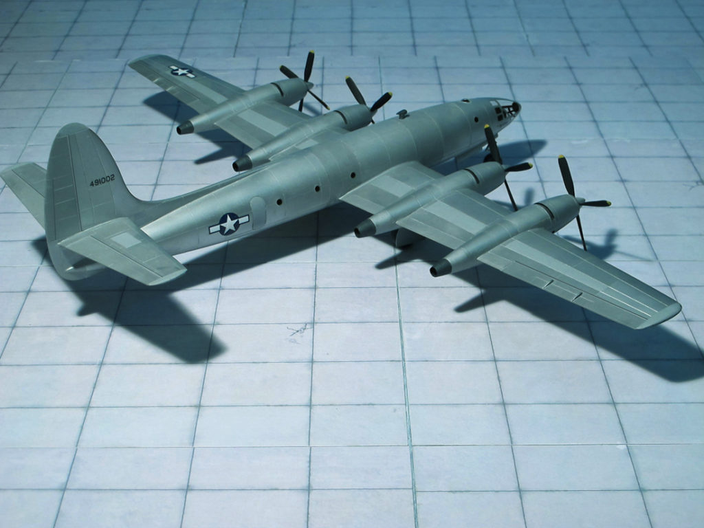
TYPE: Long-range Maritime Reconnaissance and Bomber Flying Boat
ACCOMMODATION: Crew of ten
POWER PLANT: Four Mitsubishi MK4Q “Kasei 22” radial engines, rated at 1,380 hp each
PERFORMANCE: 290 mph at 16,400 ft
COMMENT: The Kawanishi H8K “ Type 2 Large-sized Flying Boat) was an Imperial Japanese Navy flying boat used during WW II for maritime patrol duties. The Allied reporting name for the type was “Emily”.
At the same time the type’s predecessor, the Kawanishi H6K, was going into service in 1938 the Navy ordered the development of a larger, longer-ranged patrol aircraft under the designation “Navy Experimental 13-Shi Large-size Flying Boat”. The result was a large, shoulder-winged design that is widely regarded as the best flying boat of the war. Despite this, initial development was troublesome, with the prototype displaying terrible handling on the water. Deepening of the hull, redesigning of the planing bottom and the addition of spray strips under the nose rectified this. Two further prototypes— actually pre-production aircraft— joined the development program in December 1941. The IJNAF accepted the first production version as the H8K1, “Navy Type 2 Flying Boat, Model 11”, of which 14 would be built.
The H8K1 entered production in 1941 and first saw operational use on the night of 4 March 1942 in a second raid on Pearl Harbor. Since the target lay out of range for the flying boats, this audacious plan involved a refueling by submarine, some 900 km north-west of Hawaii. Two planes from the Yokohama Kokutai (Naval Air Corps) attempted to bomb Pearl Harbor, but, due to poor visibility, did not accomplish any significant damage.
Six days after the second Pearl Harbor raid one of the “Emily’s” was sent on a daylight photo-reconnaissance mission of Midway Atoll. It was intercepted by radar directed Brewster F2A-3 “Buffalo” fighters of Marine Corps squadron VMF-221 and shot down.
After serving as an engine test bed for the Kasei 22 powered H8K2, the original H8K1 experimental aircraft was again modified as the prototype for a transport version of the H8K series. The deep hull made possible the installation of two decks, the lower deck extending from the nose to the rear hull step and the upper extending from the wing centre-section to the rear of the hull. Accommodation was provided for either twenty-nine passengers or sixty-four troops, the armament was reduced to one flexible 13mm Type 2 machine gun in the nose turret and one 20 mm Type 99 Model 1 cannon in the tail turret. A total of thirty-six H8K-2L transport flying boat “Seiku” (“Clear sky) were built between 1943 and 1945 and exclusively operated by Naval transport units.
An improved version of Kawanishi H8K2 “Type 2 Flying Boat, Model 12” (Nishiki Hikōtei 12-gata) soon appeared, and it’s extremely heavy defensive armament earned it deep respect among Allied aircrews. The H8K2 was an upgrade over the H8K-1, having more powerful engines, slightly revised armament, and an increase in fuel capacity. They were used on a wide range of patrol, reconnaissance, bombing, and transport missions throughout the Pacific war. In mid 1943, many aircraft were equipped with Mark IV Model 1 ASV radar. This was to be the definitive variant, with 112 aircraft produced.
Even though far fewer Kawanishi H8Ks were built than contemporary British Short “Sunderlands” or American Consolidated PBY “Catalinas”, the Japanese flying-boat emerged from conflict as the most outstanding water-based combat aircraft of the second World War (Ref.: 1, 24).
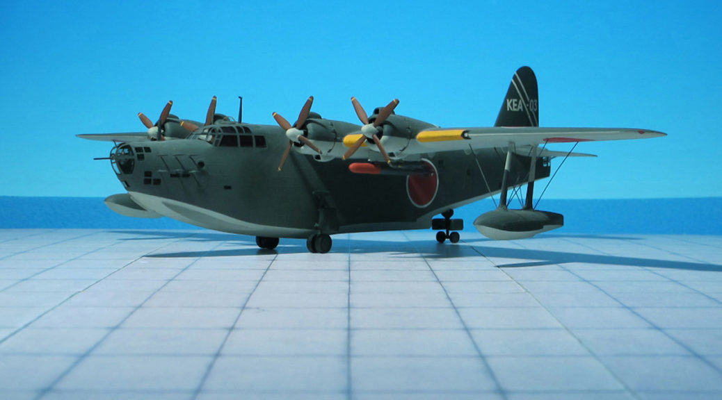
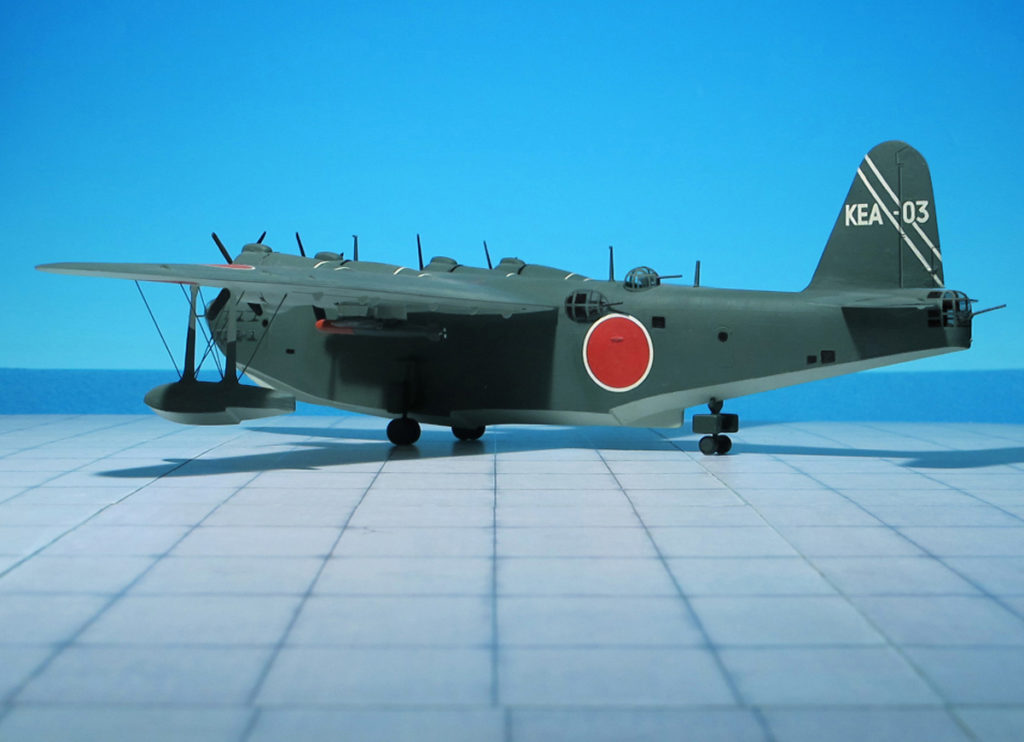
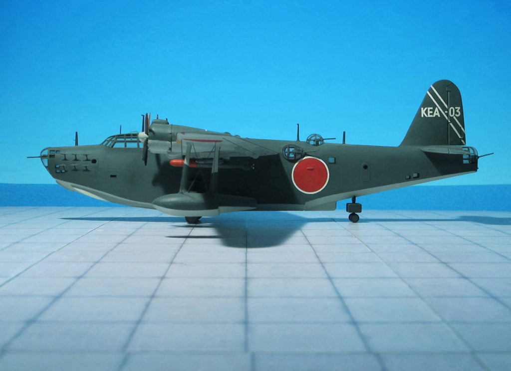
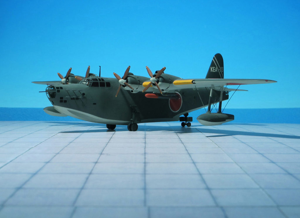
Kawanishi H8K2 “Type 2 Flying Boat, Model 12“, (Nishiki Hikōtei 12-gata), (“Emiliy”), 901st. Naval Air Corps_Combined Maritime Escort Force
Kawanishi H8K2 “Type 2 Flying Boat, Model 12“, (Nishiki Hikōtei 12-gata), (“Emiliy”), 901st. Naval Air Corps_Combined Maritime Escort Force
Kawanishi H8K2 “Type 2 Flying Boat, Model 12“, (Nishiki Hikōtei 12-gata), (“Emiliy”), 901st. Naval Air Corps_Combined Maritime Escort Force
Kawanishi H8K2 “Type 2 Flying Boat, Model 12“, (Nishiki Hikōtei 12-gata), (“Emiliy”), 901st. Naval Air Corps_Combined Maritime Escort Force
Kawanishi H8K2 “Type 2 Flying Boat, Model 12“, (Nishiki Hikōtei 12-gata), (“Emiliy”), 901st. Naval Air Corps_Combined Maritime Escort Force
Kawanishi H8K2 “Type 2 Flying Boat, Model 12“, (Nishiki Hikōtei 12-gata), (“Emiliy”), 901st. Naval Air Corps_Combined Maritime Escort Force
Kawanishi H8K2 “Type 2 Flying Boat, Model 12“, (Nishiki Hikōtei 12-gata), (“Emiliy”), 901st. Naval Air Corps_Combined Maritime Escort Force
Kawanishi H8K2 “Type 2 Flying Boat, Model 12“, (Nishiki Hikōtei 12-gata), (“Emiliy”), 901st. Naval Air Corps_Combined Maritime Escort Force
Kawanishi H8K2 “Type 2 Flying Boat, Model 12“, (Nishiki Hikōtei 12-gata), (“Emiliy”), 901st. Naval Air Corps_Combined Maritime Escort Force
Kawanishi H8K2 “Type 2 Flying Boat, Model 12“, (Nishiki Hikōtei 12-gata), (“Emiliy”), 901st. Naval Air Corps_Combined Maritime Escort Force
Kawanishi H8K2 “Type 2 Flying Boat, Model 12“, (Nishiki Hikōtei 12-gata), (“Emiliy”), 901st. Naval Air Corps_Combined Maritime Escort Force
Kawanishi H8K2 “Type 2 Flying Boat, Model 12“, (Nishiki Hikōtei 12-gata), (“Emiliy”), 901st. Naval Air Corps_Combined Maritime Escort Force
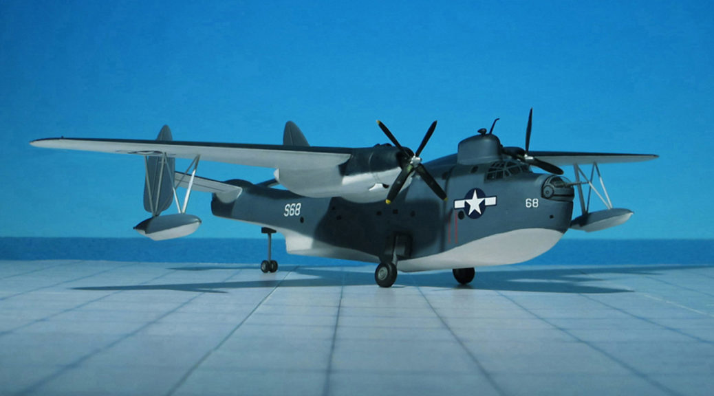
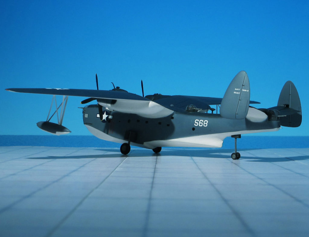
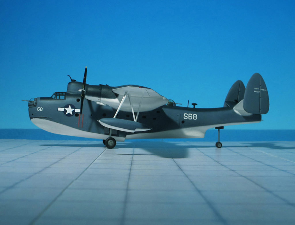
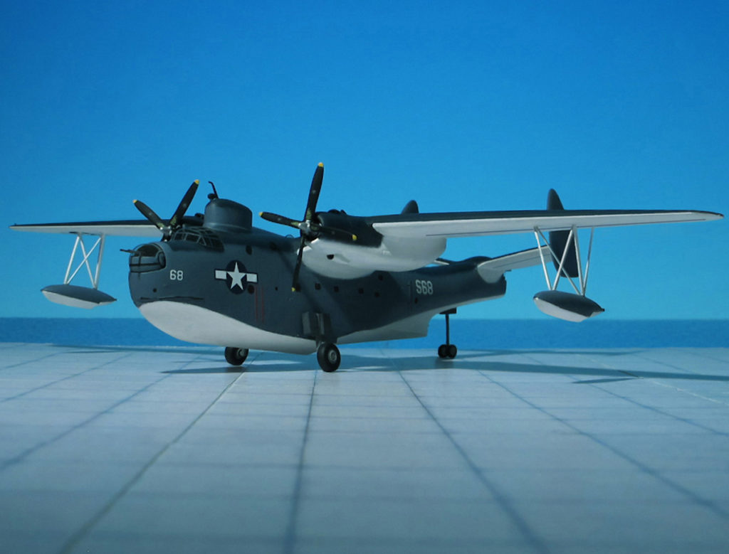
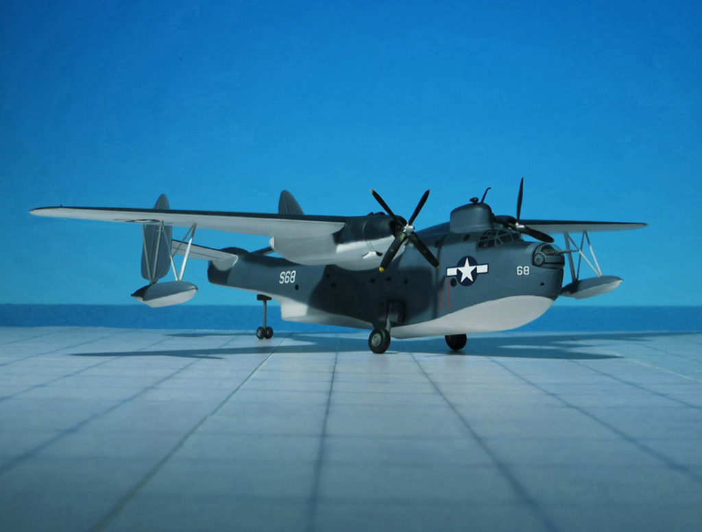
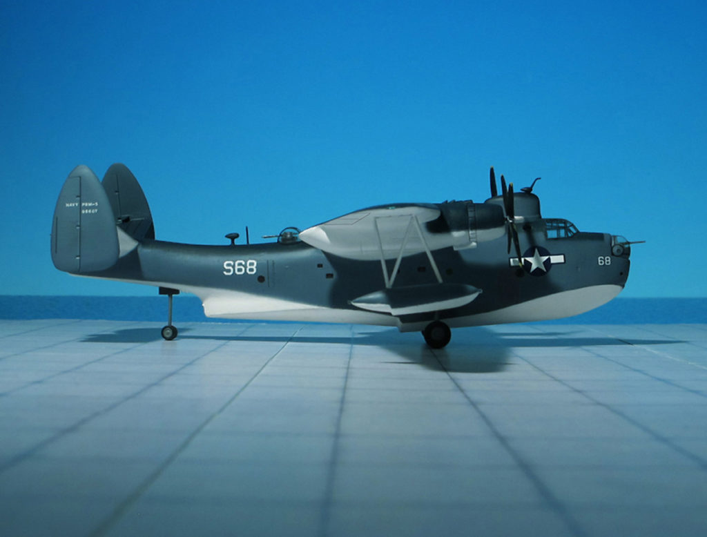
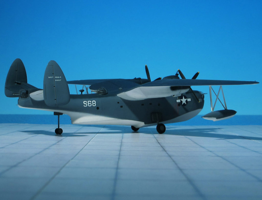
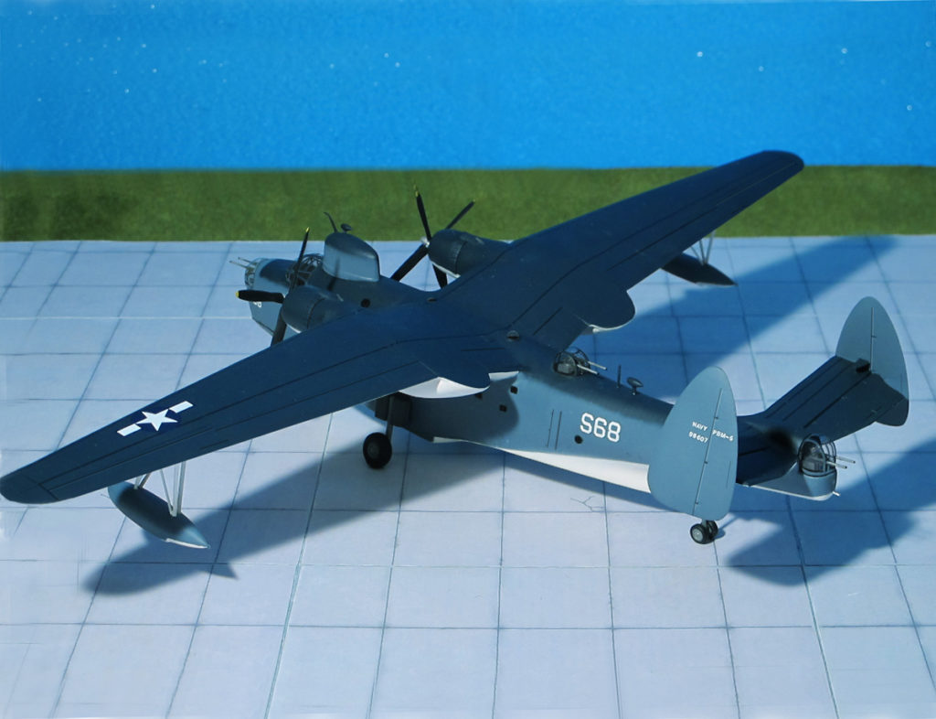
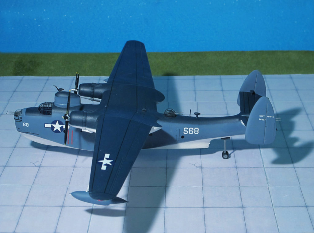
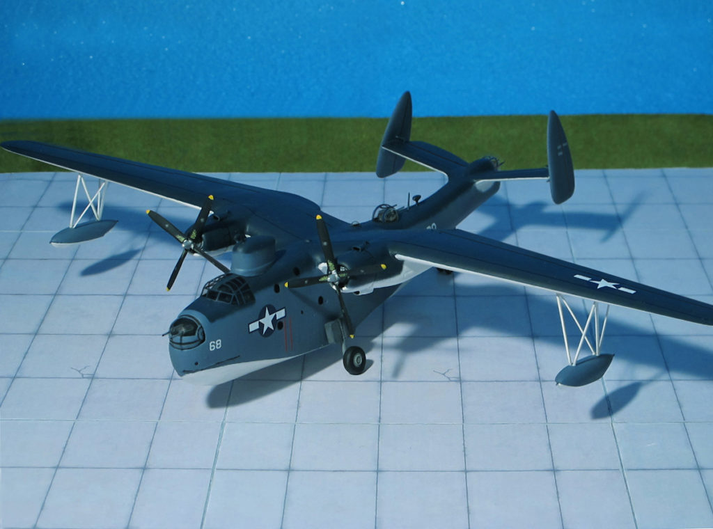
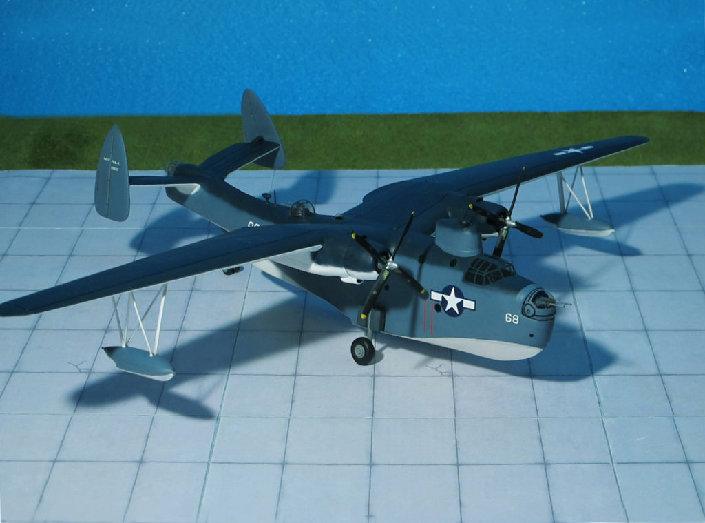
POWER PLANT: Two Pratt & Whitney R-2800 radial engines, rated at 2,100 hp each
PERFORMANCE: 205 mph
COMMENT: The Martin PBM-5 “Mariner” was an American patrol bomber flying boat of WW II. It was designed to complement the Consolidated PBY “Catalina” in service with the US Navy.
Designed in 1937, the Model 162 continued the rivalry which had sprung up between Martin and Consolidated by challenging the latter company’s PBY “Catalina”. A somewhat later design than the PBY, the Martin 162 was in due course to demonstrate a marked superiority of performance, an although it served in smaller quantities than the PBY during WW II, it continued to give important service for many years after 1945.
The Model 162 design featured a deep hull with a gull wing and two Wright “Cyclone” engines. To test the handling qualities of the design, Martin built a single-seat, quarter-scale model known as the Model 162A, an on June 1937, the US Navy places a contract for a single full-scale prototype, to be designated XPBM-1. First flown on February 1939, the XPBM-1 had 1,600 hp Wright R-2600-6 engines an provision for nose and dorsal turrets plus additional gun positions at the waist and tail position. The XPBM-1 was designed to carry 2,000 lb bombs or depth-charges. It had retractable stabilizing floats under the wing and a flat tailplane with outrigged fins. Later, dihedral was added to the tailplane, canting the fins inward to give the Martin flying boat one of its most striking characteristics. At the end of 1937 the Navy ordered 20 production model PBM-1s, for which the name “Mariner” was eventually chosen. All aircraft were completed by April 1941 and went into service during 1941.
On November 1941, orders were placed with Martin for 379 PBM-3 “Mariners” and these appeared, from 1942 onwards, in several different versions. All “Mariners” from the -3 model onward had fixed, strut-braced wing floats and lengthened engine nacelles, the latter providing stowage for bombs or depth-charges. The basic PBM-3 had Wright R-2600-12 engines, and variants includes 50 unarmed PBM-3R transports with seats for 20 passengers, 274 PBM3Cs with standardized US/British equipment and 201 PBM-3Dswith Wright R-2600-22 engines and improved armament and armor protection. Many of the PBM-3Cs and -3Ds carried search radar in a large housing above and behind the cockpit, and experience with the use of this radar led to development in 1944 of a long-range anti-submarine version, the Martin PBM-3S. A total of 156 of the latter variant were delivered, with R-2600-12 engines.
In 1943, the Martin XPBM-5 appeared with 2,100 Pratt & Whitney R-2800-22 or -34 engines, and production contracts were placed for this variant in January 1944. The PBM-5, delivered from August 1944 to the end of the war, had eight 0.50-in machine guns and AN/APS-15 radar. They were used as long-range reconnaissance aircraft and for the anti-submarine role. Production totaled 631 aircraft (Ref.: 23).
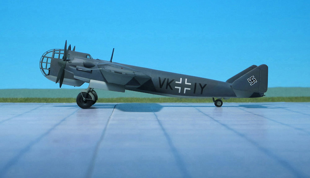
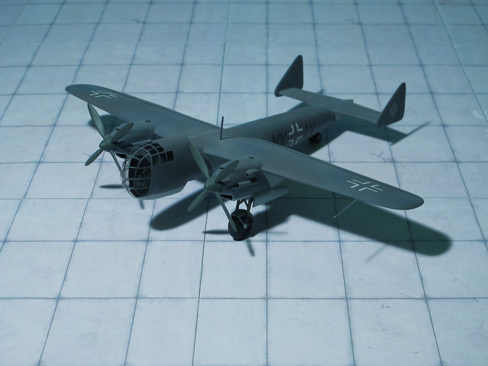
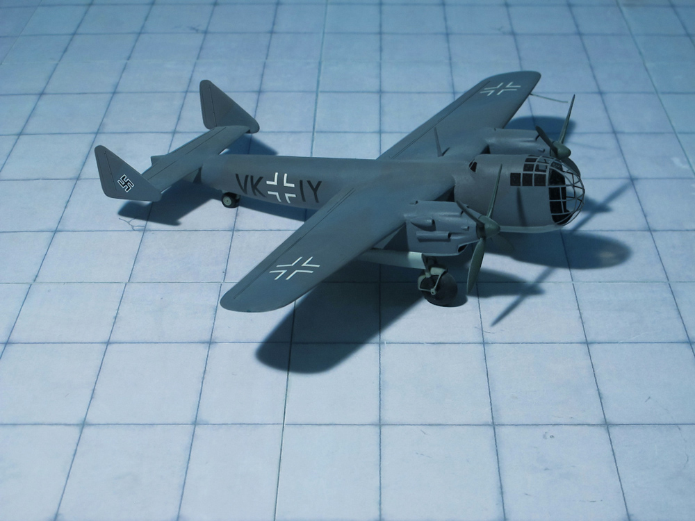
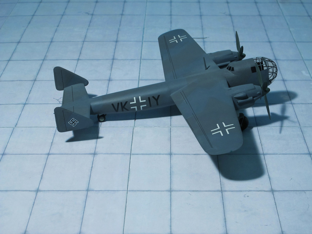
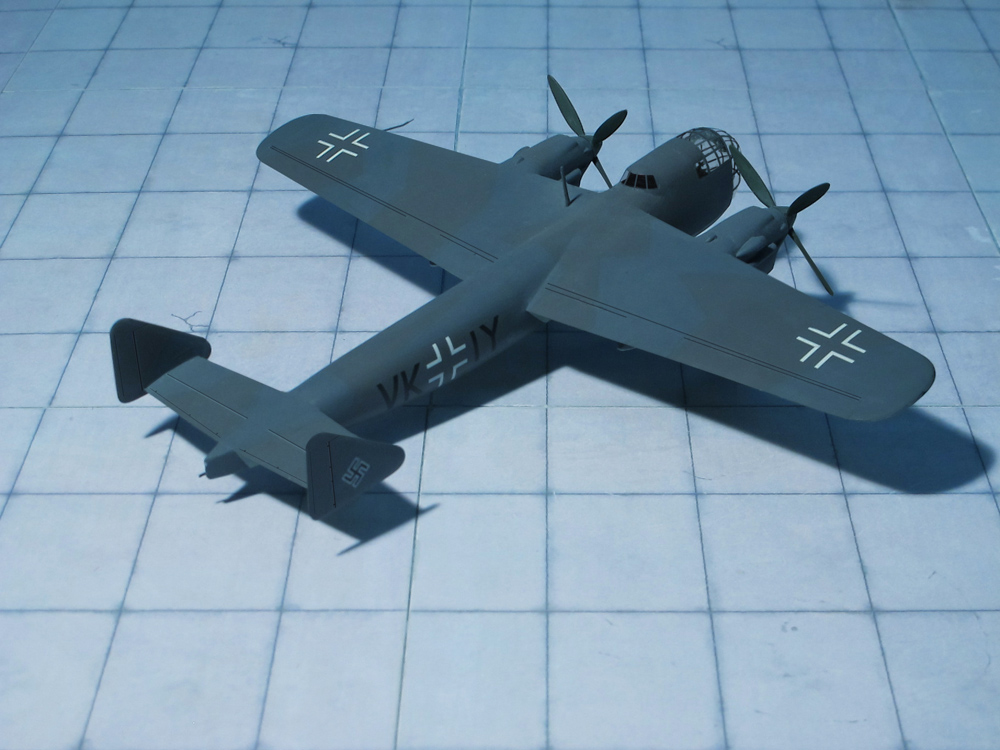
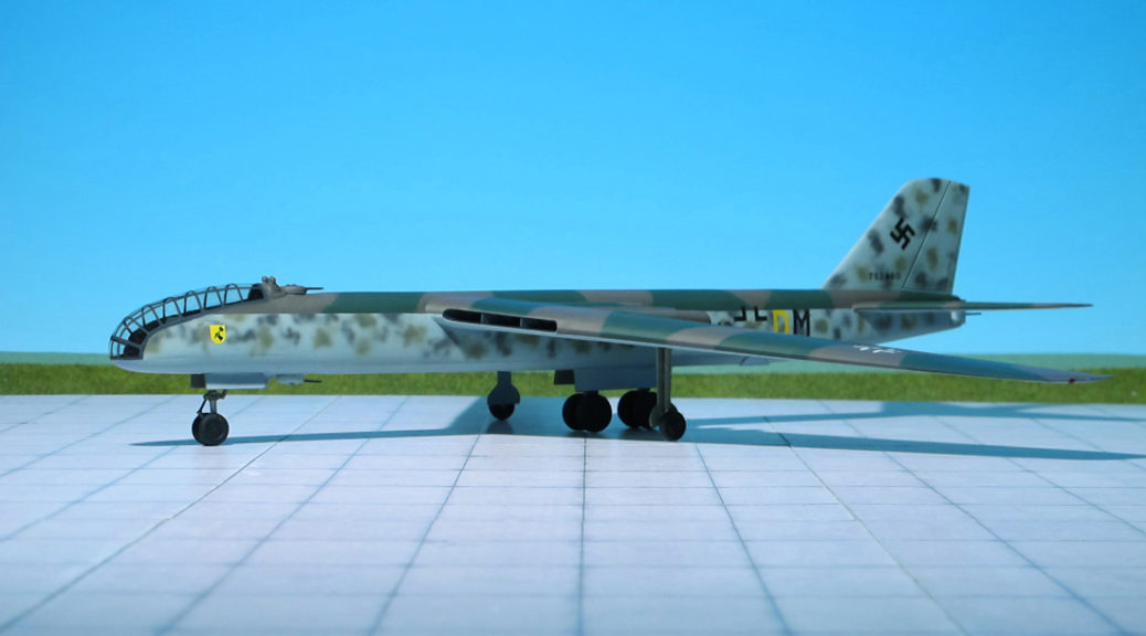
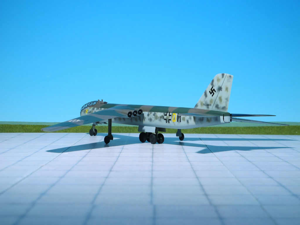
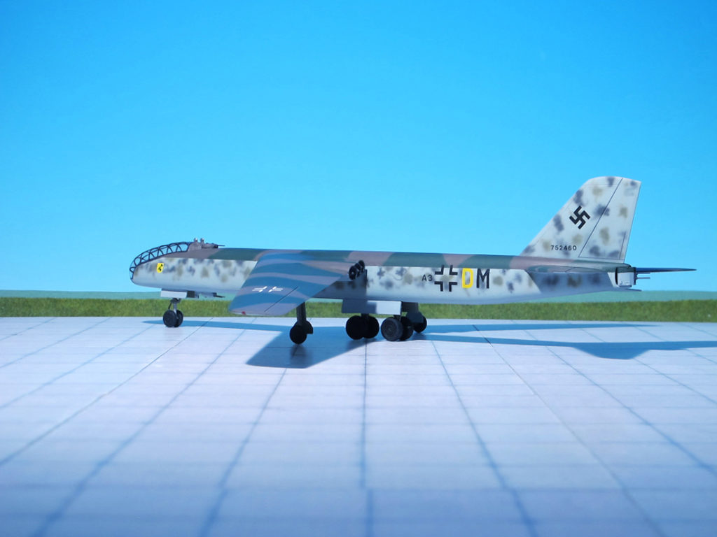
POWER PLANT: Two Daimler-Benz DB 603A liquid-cooled piston engines, rated at 1,750 hp each
PERFORMANCE: 348 mph at 19,685 ft
COMMENT: When the “Führungsstab der Luftwaffe” (Operations Staff of the Luftwaffe) drafted its so-called “Bomber B” requirement which was translated into a specification for issue to selected airframe manufactures in July 1939 by the “Technischen Amt des Reichluftfahrtministeriums” (RLM), (Technical Office of the RLM), its intention was nor merely the provision of successors for the Junkers Ju 88 and Heinkel He 111; its aim was also to carry the state of the art in medium bomber design a significant step forward.
The specification was noteworthy in the performance advances that it stipulated, and equally so in design innovations that it called for. The “Bomber B” had to possess a range of 2,237 miles do endow it with a radius of action sufficient to encompass the entire British Isles from bases that it was assumed would be available in France and Norway, a maximum speed of 373 mph at 19,685-22,965 ft., which compared favourably with the speeds of the best contemporary fighters, and a bomb load of 4,410 lb. It had to carry three or four crew members, possess a loaded weight of the order of 44,090 lb., and be of twin-engined configuration, utilizing the extremely advanced 24-cylinder liquid-cooled Daimler-Benz DB 604 or Junkers Jumo 222 engines then at an early stage in development, but the really radical demands of the specification were its insistence on pressurized accommodation for the crew, and the use of remotely-controlled barbettes to house defensive armament.
Initially, the specification was issued to four manufacturers: Arado, Dornier, Focke-Wulf and Junkers, although the scope of the contest was later to be broadened to include Henschel (Henschel Hs 130) when it was realized by the RLM that this company has more pressure cabin experience than any other contestants, with the possible exception of Junkers. The final proposals of the original four competing companies were submitted to the “Technisches Amt” in July 1940, and evaluation eliminated the Arado contender, the Ar 340, prototypes being ordered of each of the other contender, Dornier Do 317, Focke-Wulf Fw 191 and Junkers Ju 288.
Dornier’s proposal was based broadly on the design of the Dornier Do 217, the four crew members being housed ahead of the wing in a pressure cabin which, taking the form of a detachable compartment pressurized by tapping the superchargers of the Daimler-Benz DB 604 engines, was extensively glazed by a series of curved panels.
Two versions of the Do 317 were proposed: the simplified Do 317A, powered by two DB 603A engines (instead of the troublesome Daimler-Benz DB 604) and featuring conventional defensive armament, and the more advanced Do 317B with the heavy 1.5 tonnes apiece, counter-rotating DB 610A/B “power system” engines, remotely aimed “Fernbedienbare Drehlafette” (FDL)-style gun turrets (remotely-controlled turrets), heavier bombload, and an extended wing.
Six prototypes of the Dornier Do 317A were ordered, and the first of these, the Do 317 V1, commenced its flight test program on September 1943. The Do 317 V1 was very similar in appearance to the later Dornier Do 217K and -M subtypes, with a visually reframed slight variation of its multiple glazed-panel “stepless cockpit”, fully glazed nose design that accommodated a pressurized cabin provision, and triangular tailfins. Trials with the Do 317 V1 revealed no real performance advance over the Do 217. However, it was clear even at this point that the call for designs was to some extent a formality, as the Junkers Ju 288 design had already been selected for production. So it was decided to complete the remaining five prototypes without cabin pressurization equipment and fit them out with FuG 230 “Kehl-Straßburg” radio guidance transmitting gear to employ them as Henschel Hs 293 missile launchers. In this form, the prototypes were redesignated Dornier Do 217R. At this time, the Do 317B project was abandoned due to changing wartime conditions (Ref.: 7, 24).
ACCOMMODATION: Crew of two plus eight passengers or equivalent cargo
POWER PLANT: Two Hitachi Ha-13a radial engines, rated at 510 hp each
PERFORMANCE: 233 mph
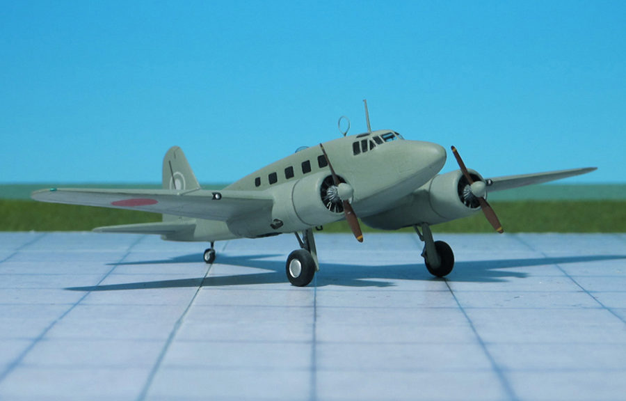
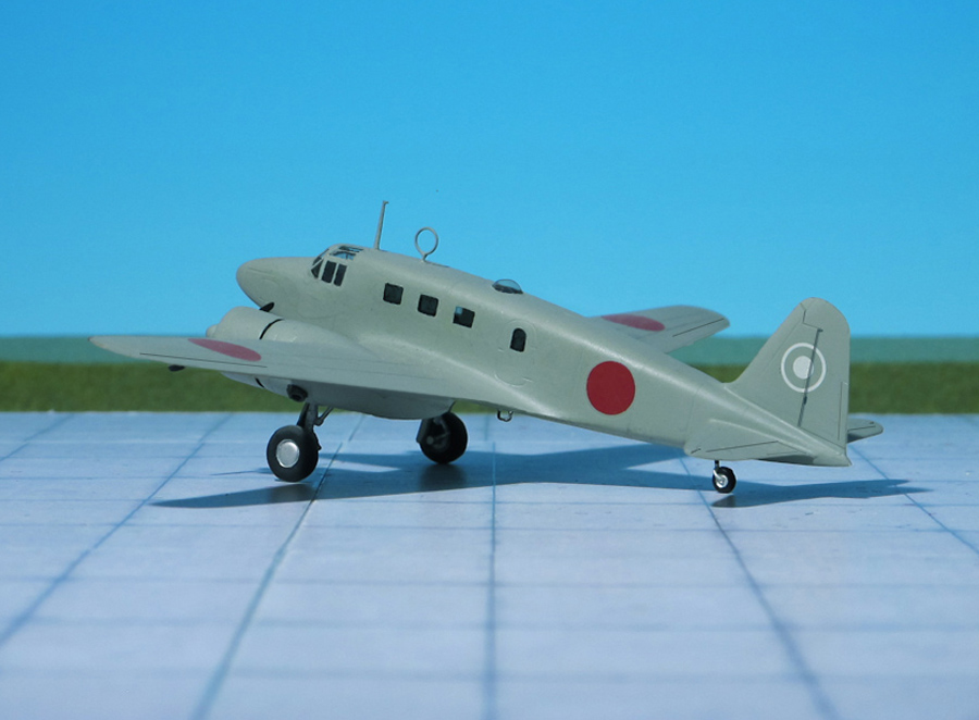
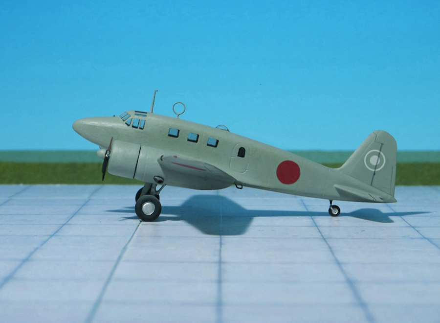
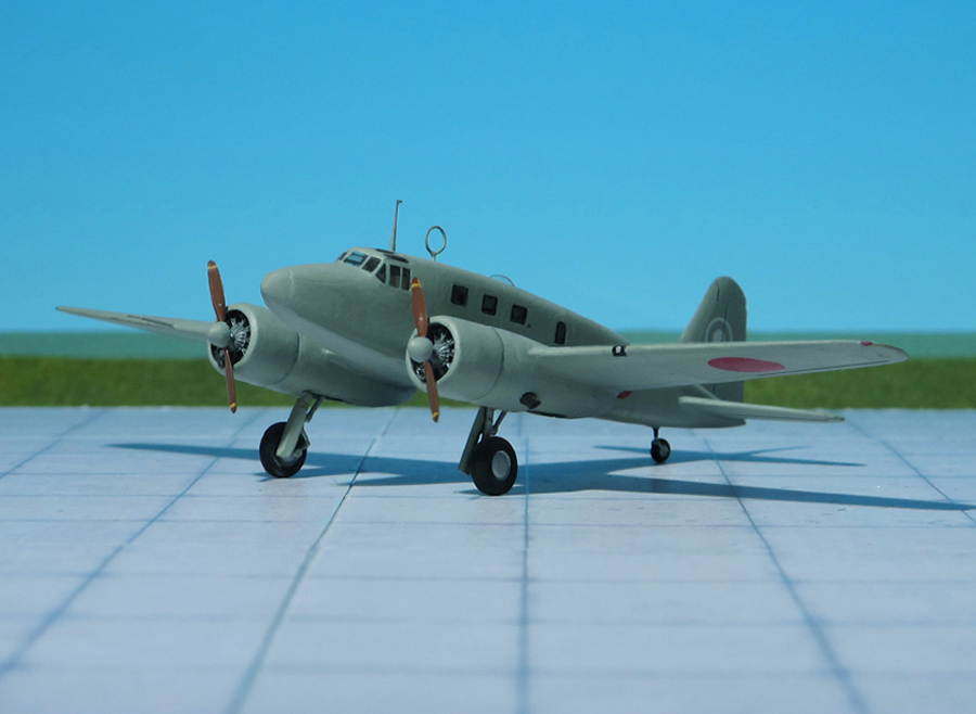
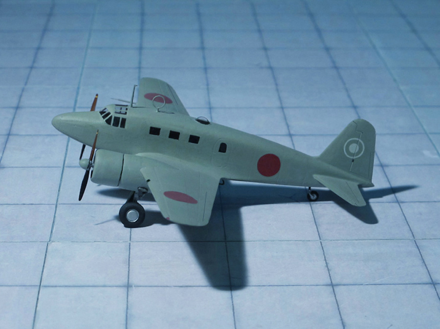
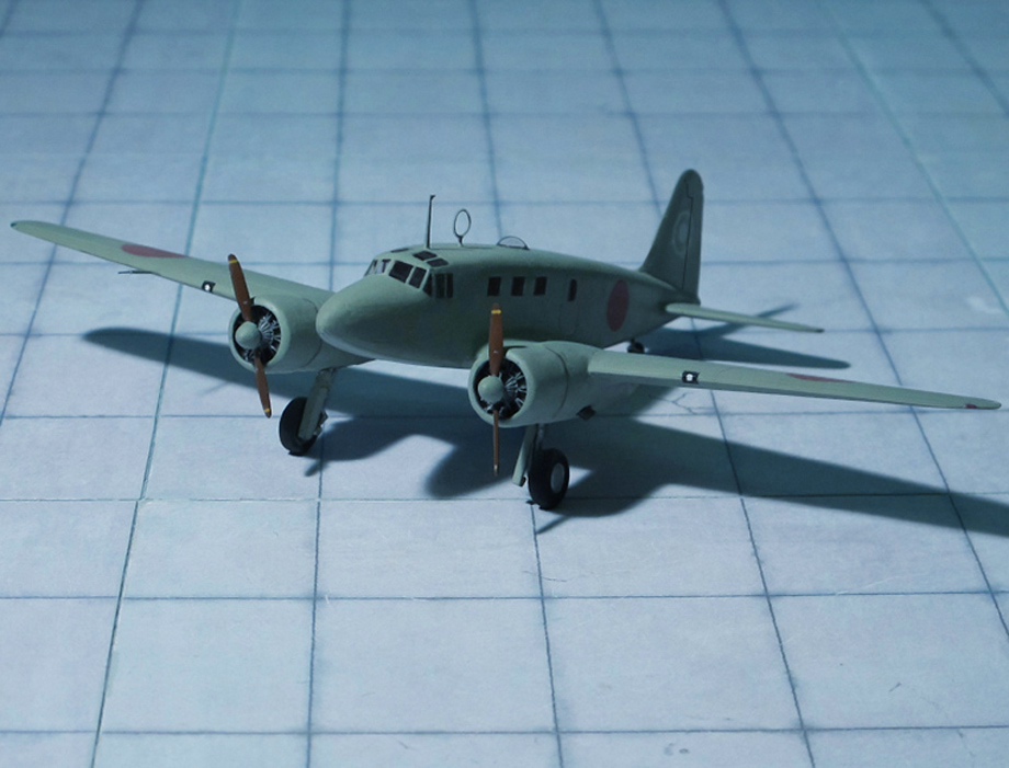
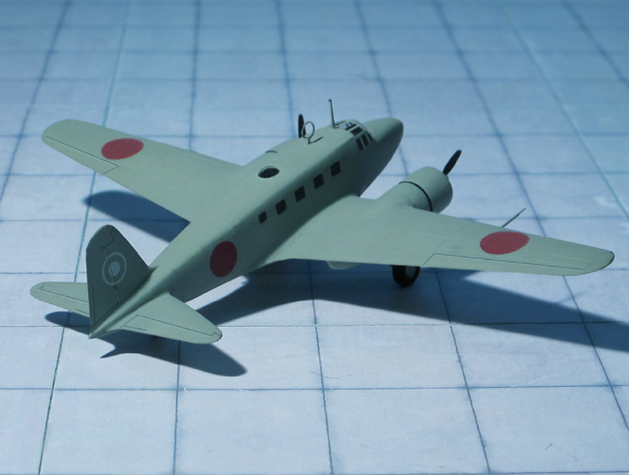
COMMENT: The Tachikawa Ki-54 was a Japanese twin-engine advanced trainer and light transport aircraft used during WW II. The aircraft was developed in response to an Imperial Japanese Army Air Force requirement for a twin-engine multi-purpose trainer, principally for crew training. The prototype first flew in summer 1940 and, on completing trials, entered production in 1941 as “Army Type 1 Advanced Trainer Model A” (Tachikawa Ki-54a). The Ki-54a was soon followed by the Tachikawa Ki-54b as “Army Type 1 Operations Trainer Model B” and Tachikawa Ki-54c as “Army Type 1 Transport Model C”.
The Tachikawa Ki-54c was a light transport and communication version characterized by its smooth upper fuselage line and was fitted with eight seats. A similar version was built in small numbers as Tachikawa Y-59 for civil operators. Late in the war an all-wood version of the Ki-54c, the Tachikawa Ki-110 was built, but the aircraft was destroyed during an American air raid.
As a crew trainer and light transport, the Tachikawa Ki-54 was one of the most successful Japanese aircraft of the war and was well known to the Allies which named it “Hickory” regardless of the version. The code name “Joyce” was erroneously assigned to a non-existent light bomber version.
A total of 1,368 Ki-54 were built by Tachikawa Hikoki K.K. during the war. A few captured aircraft were flown after the war by various users (Ref.: 1, 24).
Tachikawa Ki-54c (Army Type 1 Transport Model C), (“Hickory”), 27th Hikodan
Tachikawa Ki-54c (Army Type 1 Transport Model C), (“Hickory”), 27th Hikodan
Tachikawa Ki-54c (Army Type 1 Transport Model C), (“Hickory”), 27th Hikodan
Tachikawa Ki-54c (Army Type 1 Transport Model C), (“Hickory”), 27th Hikodan
Tachikawa Ki-54c (Army Type 1 Transport Model C), (“Hickory”), 27th Hikodan
Tachikawa Ki-54c (Army Type 1 Transport Model C), (“Hickory”), 27th Hikodan
Tachikawa Ki-54c (Army Type 1 Transport Model C), (“Hickory”), 27th Hikodan
Tachikawa Ki-54c (Army Type 1 Transport Model C), (“Hickory”), 27th Hikodan
Tachikawa Ki-54c (Army Type 1 Transport Model C), (“Hickory”), 27th Hikodan
Tachikawa Ki-54c (Army Type 1 Transport Model C), (“Hickory”), 27th Hikodan
Tachikawa Ki-54c (Army Type 1 Transport Model C), (“Hickory”), 27th Hikodan
Tachikawa Ki-54c (Army Type 1 Transport Model C), (“Hickory”), 27th Hikodan
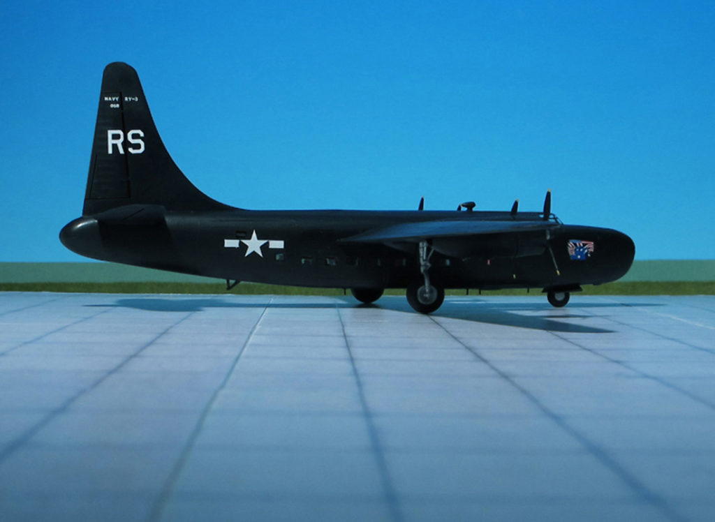
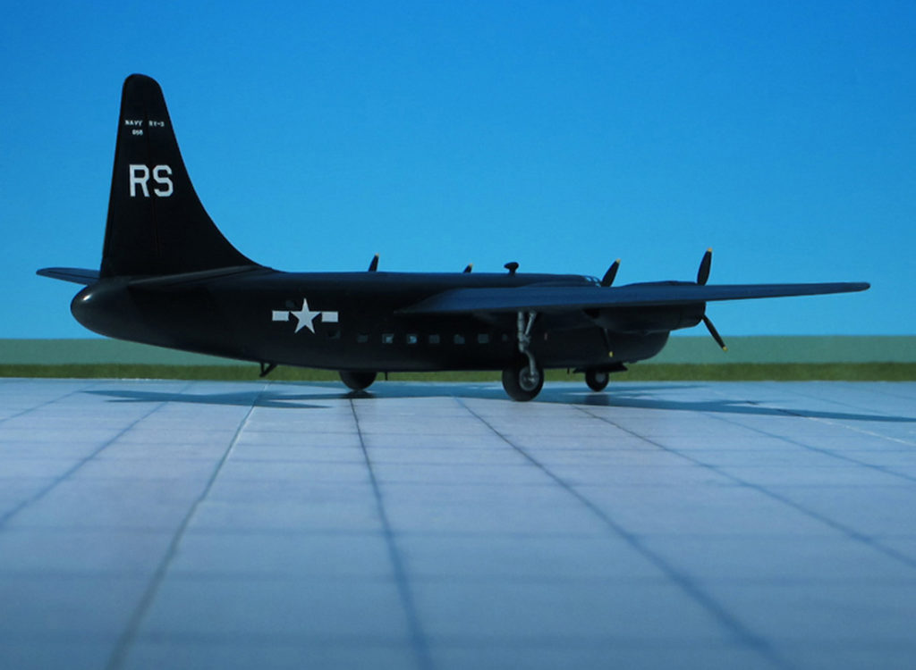
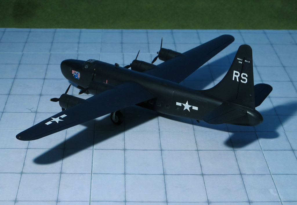
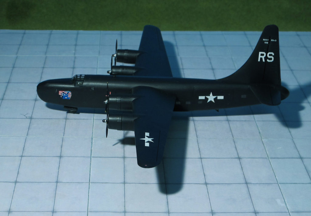
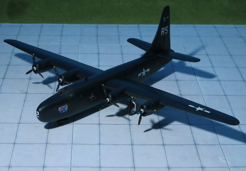
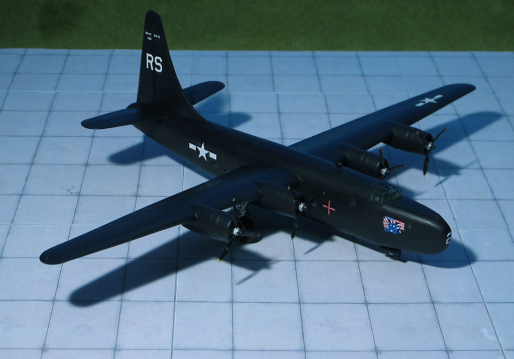
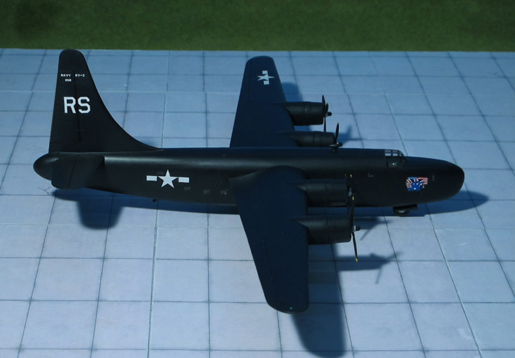
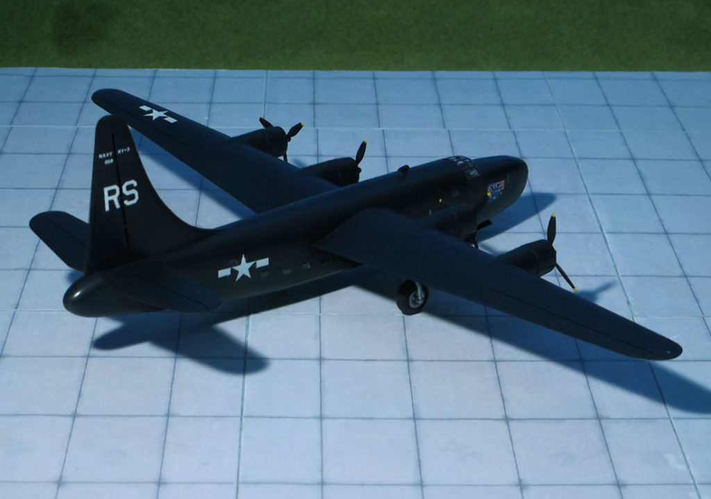
ACCOMMODATION: Crew of four plus 25 troops or up to 4,500 kg cargo
POWER PLANT: Four Pratt & Whitney R-1820-94 radial engines with General Electric turbo-superchargers, rated at 1,350 hp each
PERFORMANCE: 300 mph at 25,000 ft
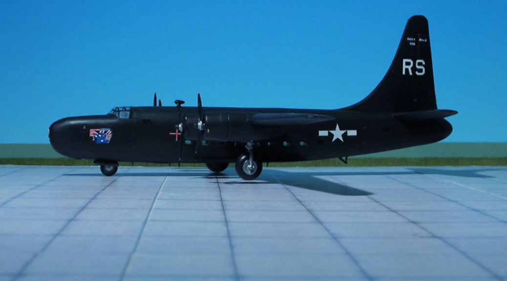
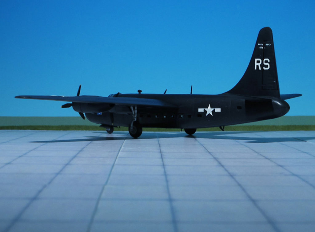
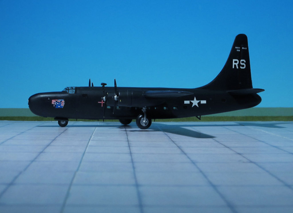
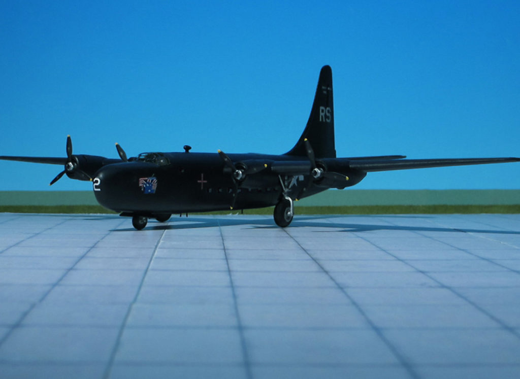
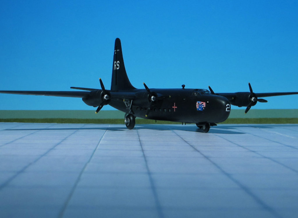
COMMENT: The Consolidated RY-3 was a troop and cargo transport aircraft built for the United States Navy on the basis of the patrol bomber Convair PB4Y-2 “Privateer”. This, on the other hand, was a US Navy derivative of the famous USAAF Consolidated B-24 “Liberator” heavy bomber.
In 1942, an urgent need was recognized for a heavy cargo and personnel transport with longer range and better high-altitude performance than the Douglas C-47 “Skytrain”, the most widely available USAAF transport aircraft at the time. So the Consolidated Aircraft Company hastily designed a cargo and transport variant of the “Liberator” bomber under the designation Consolidated C-87 “Liberator Express”. Production began in 1942 and a total of 287 C-87s were built alongside the B-24 at the Consolidated Aircraft plant in Fort Worth, Texas. The C-87 could be fitted with removable seats and racks to carry personnel or litters in place of cargo. In its final configuration, the C-87 could carry between 20 and 25 passengers or 4,500 kg of cargo. Because of war production bottlenecks and shortages, many C-87 aircraft were fitted with turbo-superchargers producing lower boost pressure and power than those fitted to B-24s destined for combat use, and ceiling and climb rate were accordingly adversely affected.
Despite its shortcomings and unpopularity among its crews, the C-87 was valued for the reliability of its Pratt & Whitney engines, superior speed that enabled it to mitigate significantly the effect of head and cross winds, a service ceiling that allowed it to surmount most weather fronts, and range that permitted its crews to fly “pressure-front” patterns that chased favorable winds. The C-87 was never fully displaced on the air routes by the Douglas C-54 “Skymaster” and Curtiss C-46 “Commando”, which offered similar performance combined with greater reliability and more benign flight characteristics.
One of the last developments of the basic USAAF Consolidated B-24 “Liberator” bomber design was a Navy contracted, single tail version with an extended fuselage. Built in San Diego its USN designation was Consolidated PB4Y-2 “Privateer” and the aircraft’ design based on the Consolidated PB4Y-1, the US Navy version of the B-24 “Liberator”.
The “Privateer” was externally similar to the “Liberator”, but the fuselage was longer, and had a tall single vertical stabilizer rather than the PB4Y-1’s twin tail configuration. The single vertical tail was adopted from the USAAF’s canceled B-24N design (and was slightly taller on the “Privateer”) because it would increase stability at low to medium altitudes for maritime patrol.
39 out of totally built 739 „Privateers“ were converted for transport duties as Consolidated RY-3, and were used by the RAF Transport Command No. 231 Squadron, U.S. Marine Corps, and one was used by the RCAF (Ref.: 24).
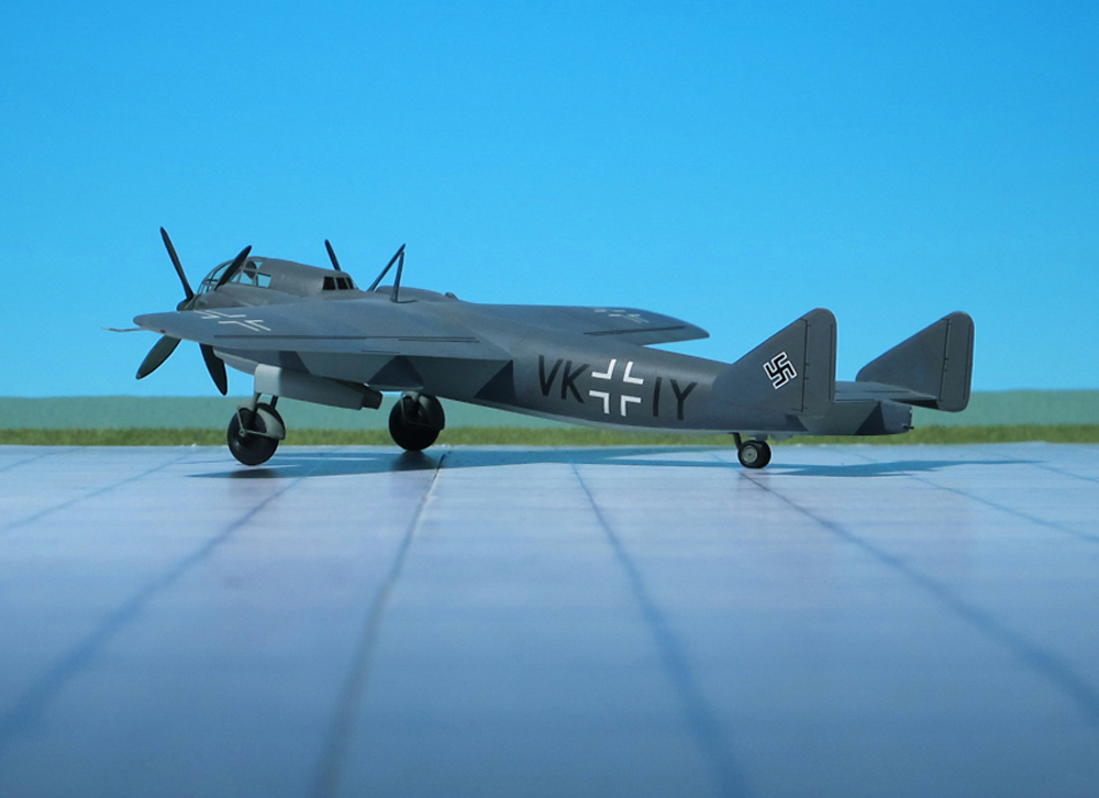
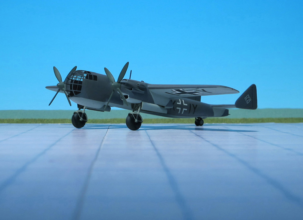
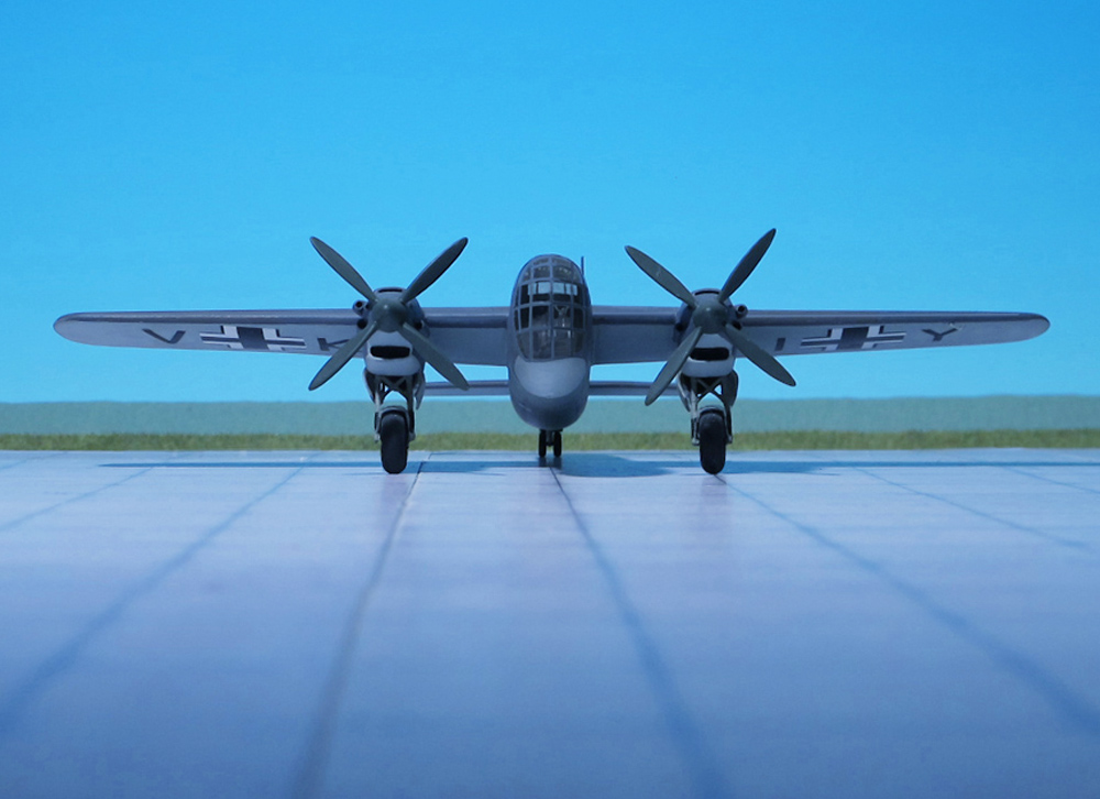
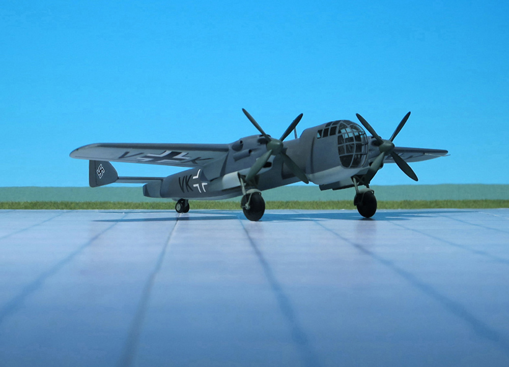
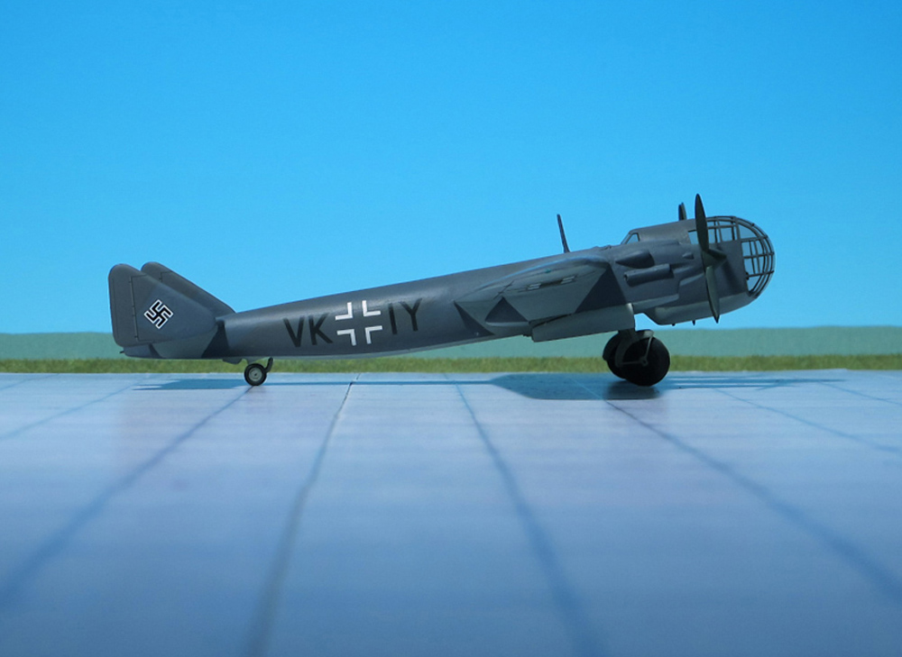
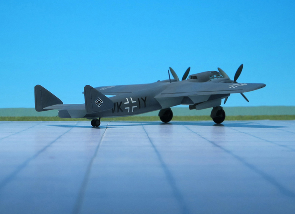
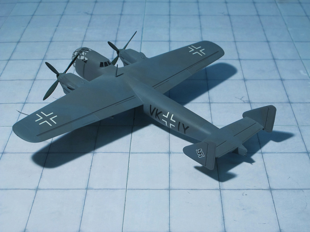
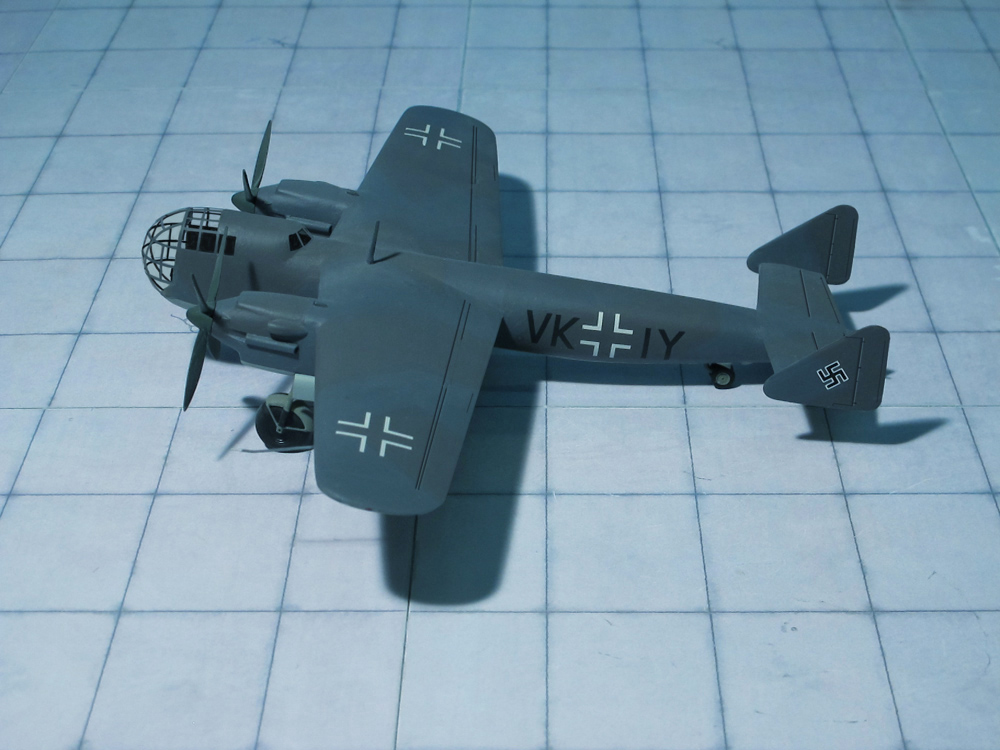
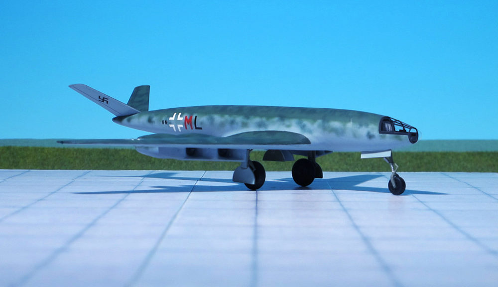
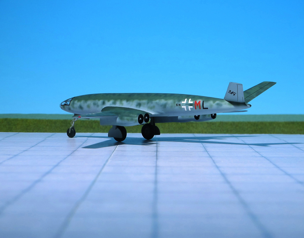
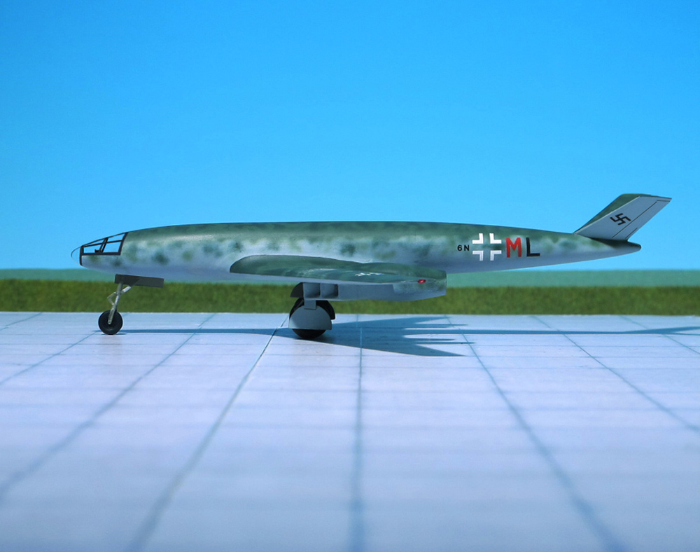
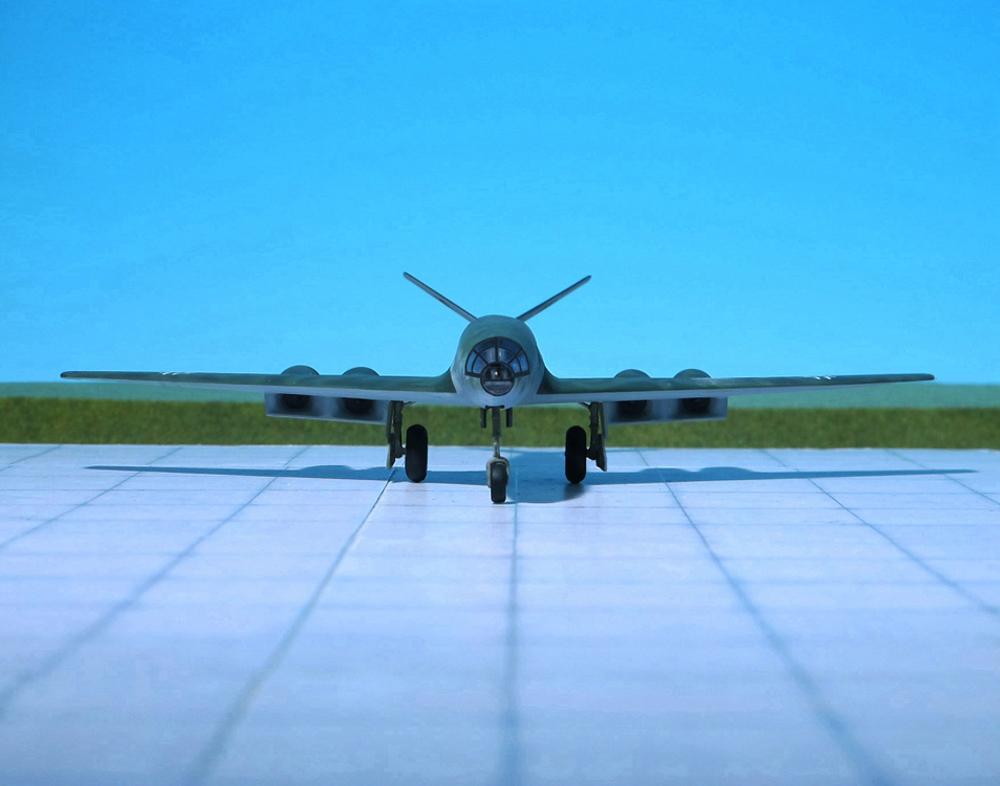
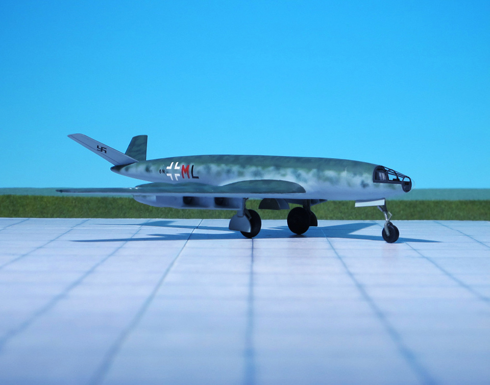
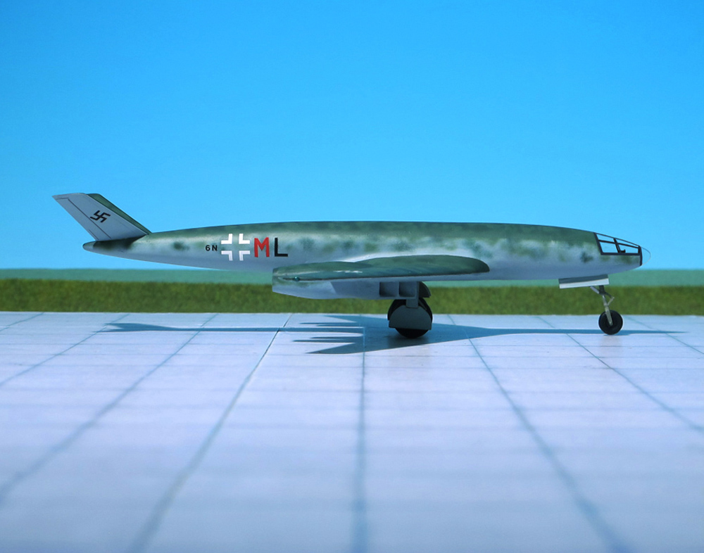
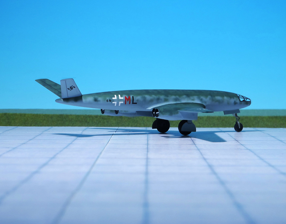
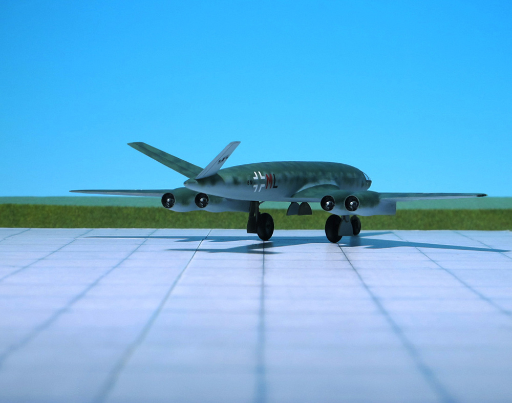
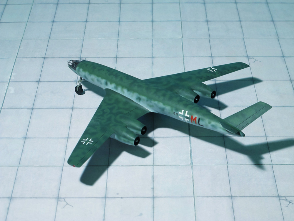
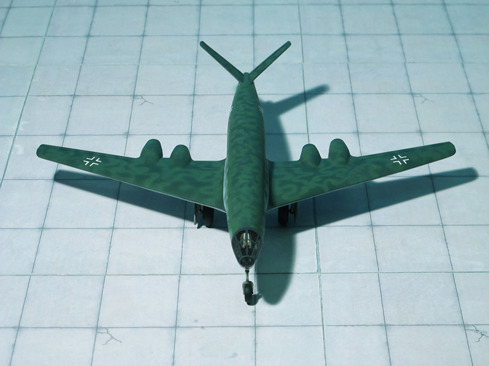
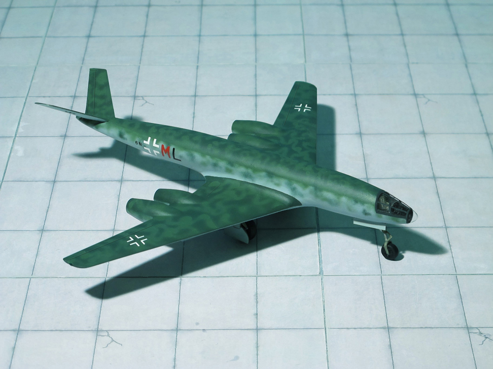
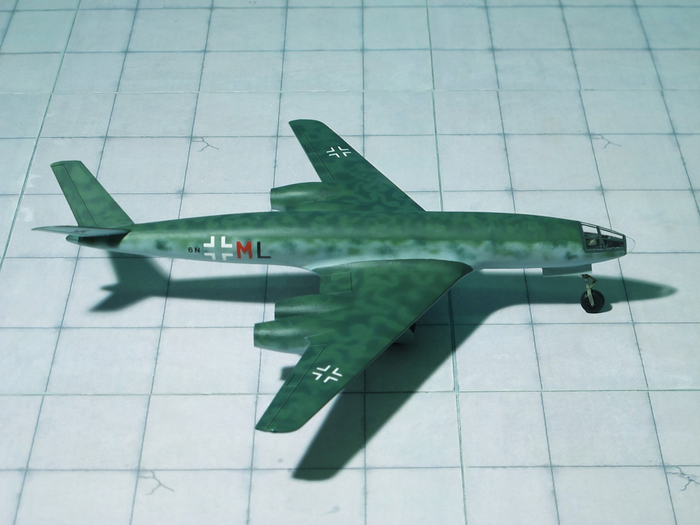
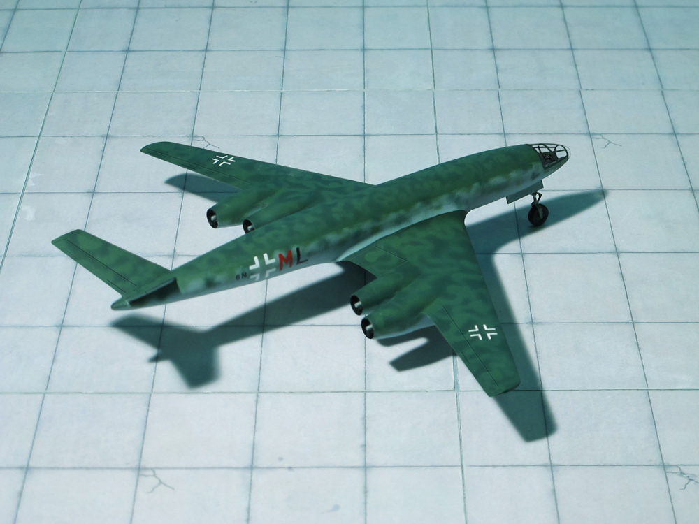
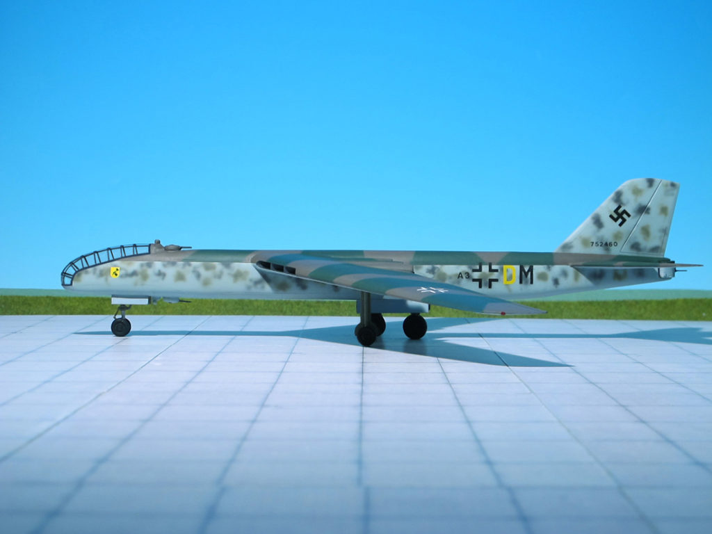
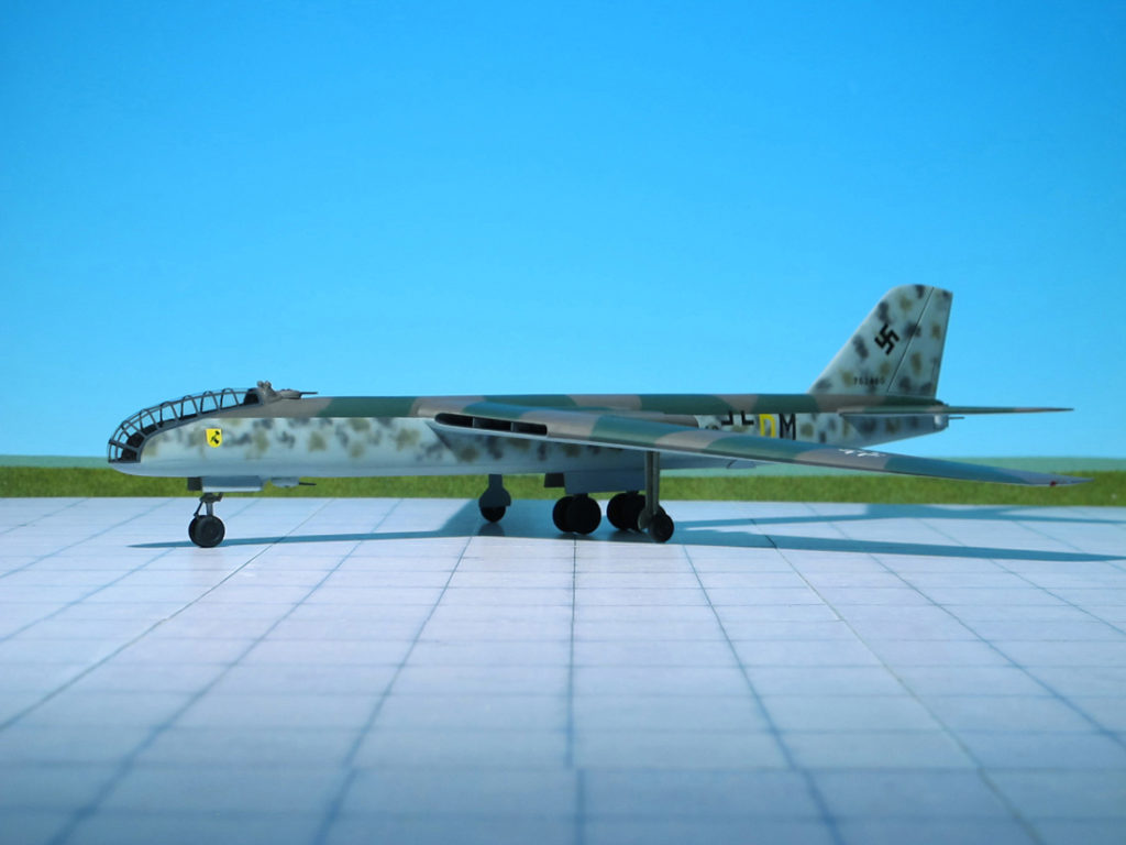
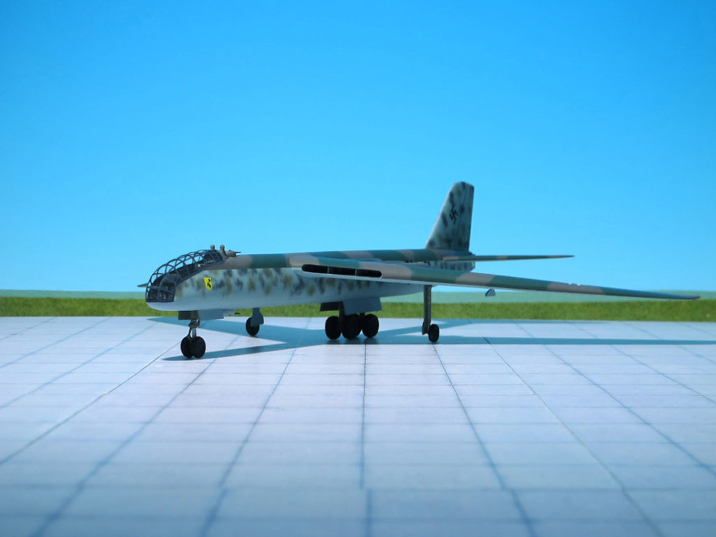
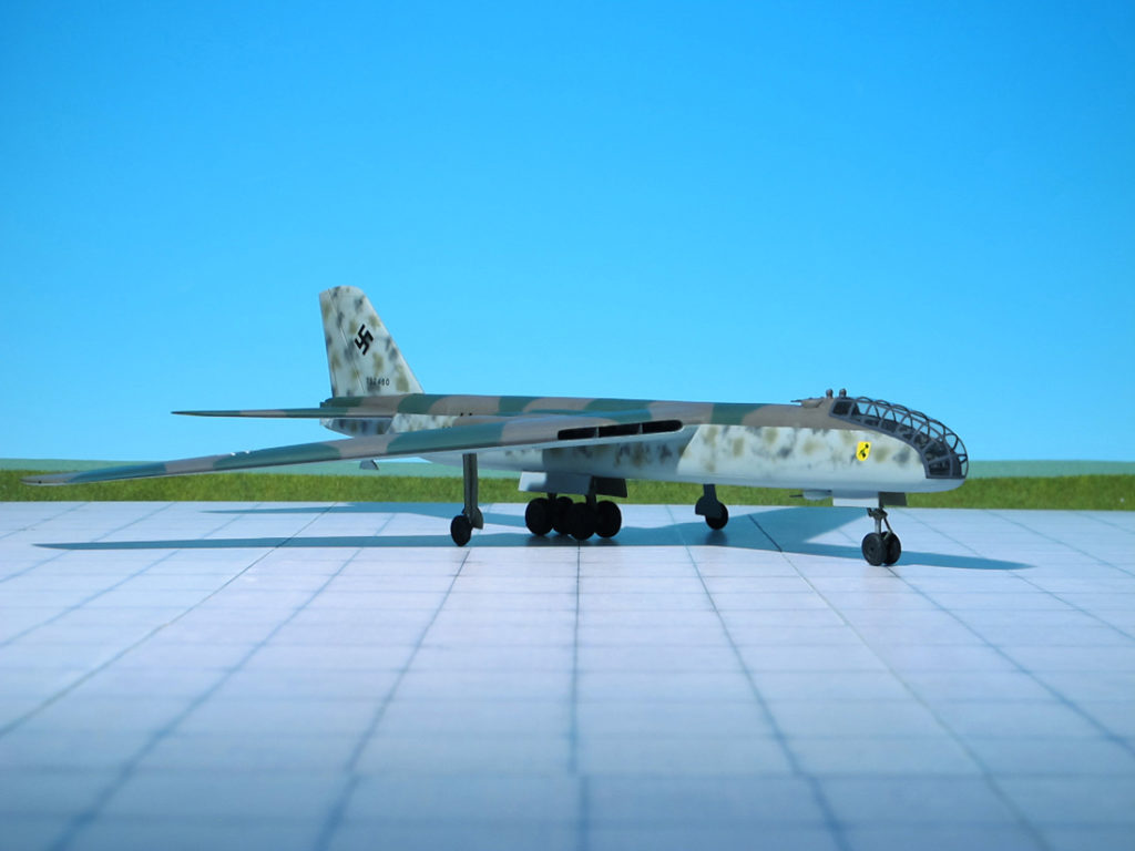
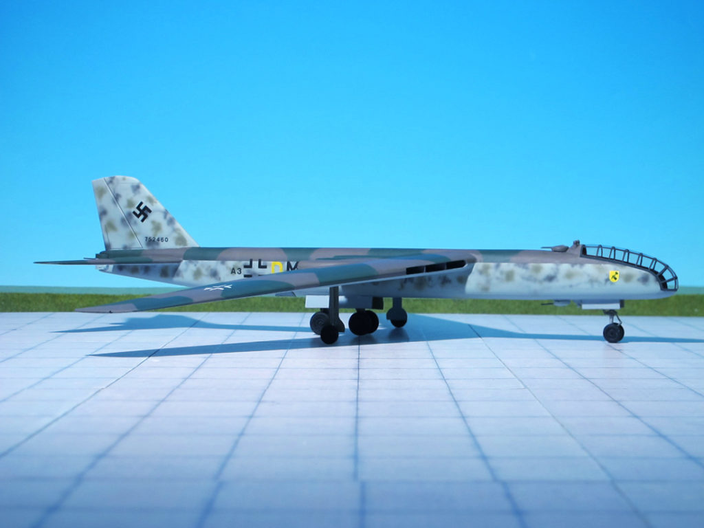
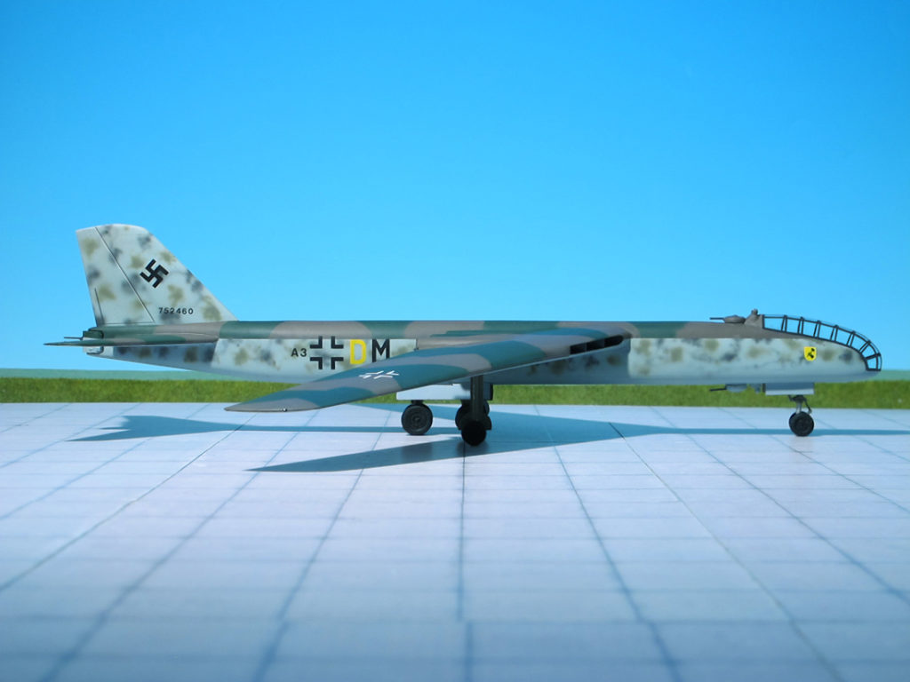
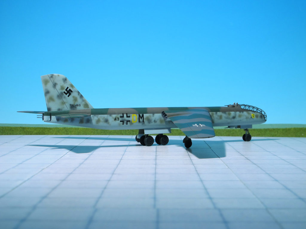
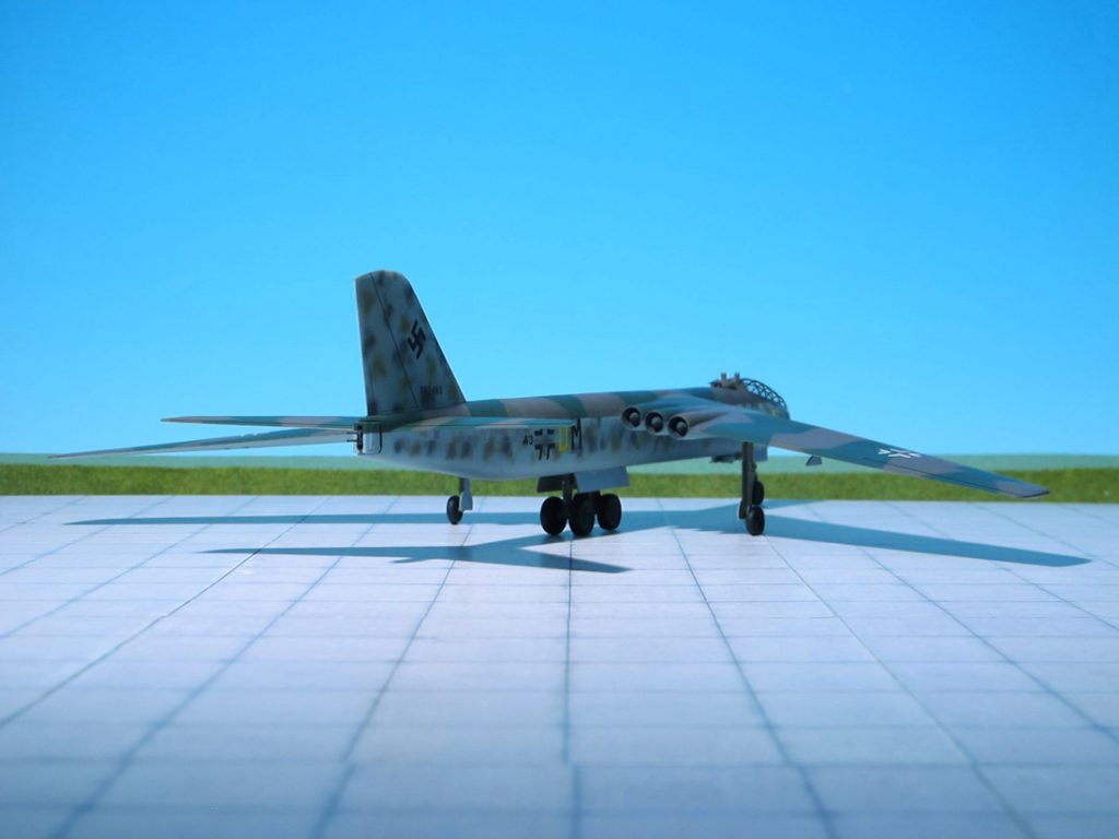
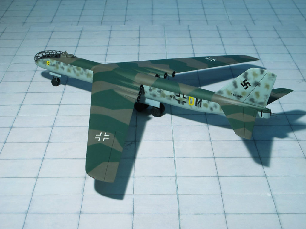
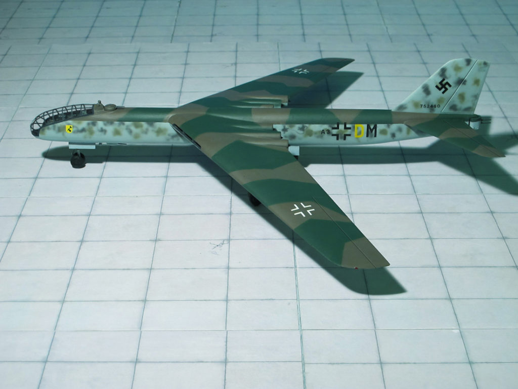
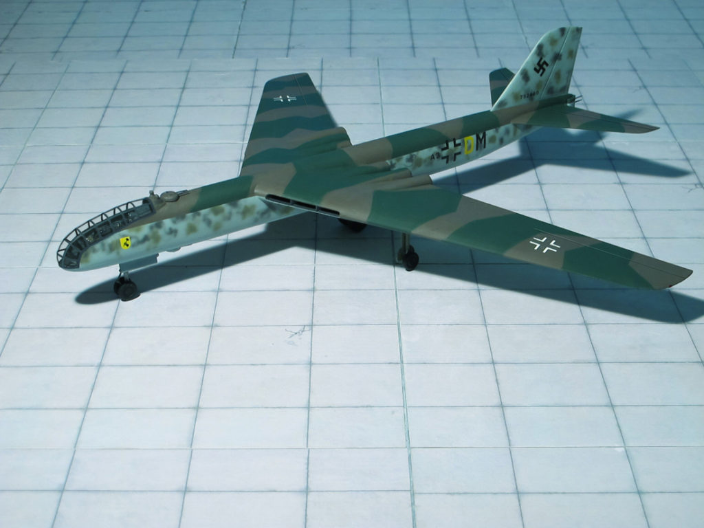
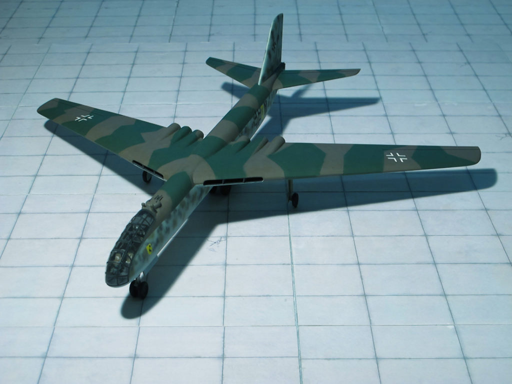
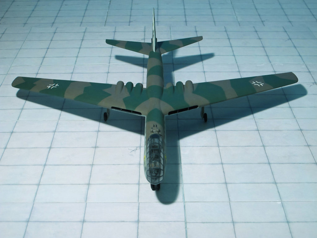
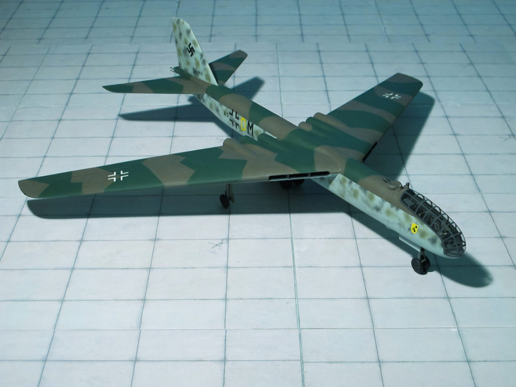
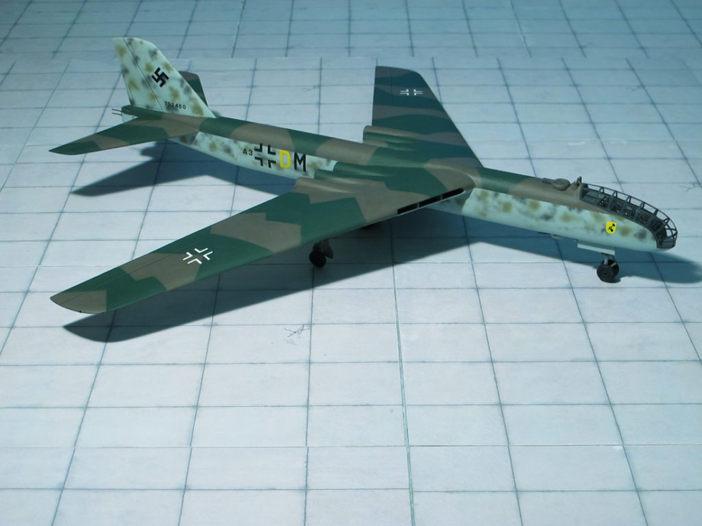
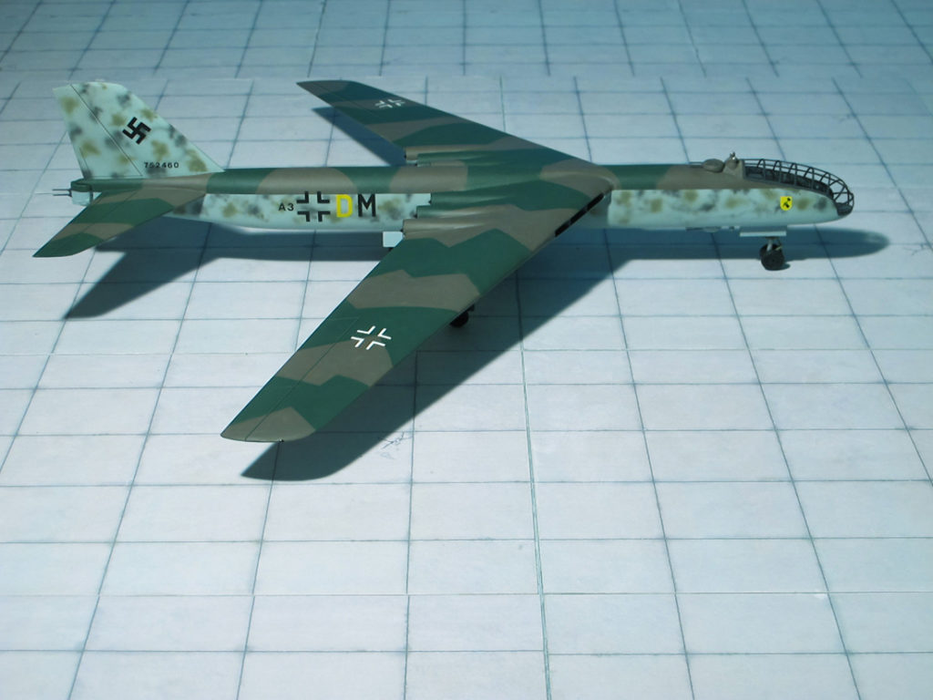
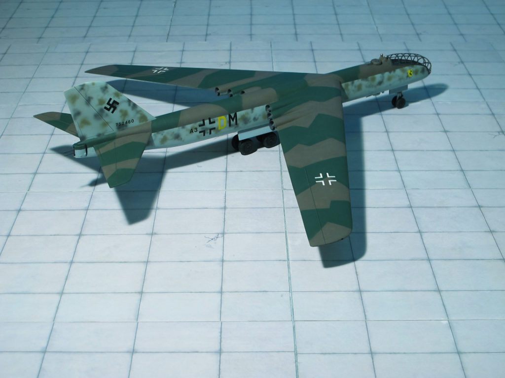
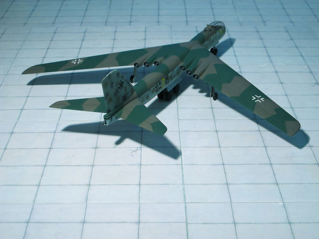
POWER PLANT: Four Heinkel/Hirth HeS 011 turbojet engines, rated at 1,200 kp each
PERFORMANCE: 528 mph
COMMENT: In January/February 1945, only four month before the German “Third Reich” surrendered, Messerschmitt proposed two designs of a “Fernbomber” (Long-distant range/long-range bomber), the Me P.1108/I and –II. Although no post-war information provided by Messerschmitt’s employees could be independently verified, since all data had already been removed by the French it seems that both projects were designed by Dr. Wurster from Messerschmitt to a concept by Dr. Alexander Lippisch.
While the Messerschmitt Me P.1108/I, (design drawing Nr. IX-126 from 28th February, 1945) was a more conventional design with a fuselage, 35 degree back-swept wings and a butterfly-type tailplane, the Me P.1108/II (design drawing Nr.117 from January 12th, 1945) was a flying wing concept with 40 degrees sweep of the leading edge without any tailplane. Common to both projects were the installation of four Heinkel/Hirth HeS 011 turbojet engines, the air intakes were under the wings or in the wings leading edge. Calculated fully loaded weight was to be 30 tons, a range of 4,300 mi at a speed of 500–530 mph and a height of 30,000–39,000 ft. was estimated.
The Messerschmitt Me P.1108/I design had an aerodynamic clear fuselage with circular cross section and low positioned swept back wing with four He S 011 turbojet engines in paired nacelles half-embedded in the wing trailing edge. These were fed by a common intake on each lower wing surface. A two man crew sat in tandem position in a pressurized cockpit in the extreme nose of the aircraft. A tricycle landing gear arrangement was designed, with the main wheels retracting into the fuselage. It was planned that the armament of the production aircraft should consist of three twin 20mm cannon turrets, two located on the back of the fuselage and aft of the cockpit and one under the fuselage. All were remotely controlled from the cockpit.
Understandably, at the end of March 1945, only few weeks before the total collapse of the “Third Reich” Messerschmitt was ordered by the RLM to cease all development on long range bomber designs (Ref.: 15, 20).
Messerschmitt Me P.1108/I “Fernbomber“ with fuselage
Messerschmitt Me P.1108/I “Fernbomber“ with fuselage
Messerschmitt Me P.1108/I “Fernbomber“ with fuselage
Messerschmitt Me P.1108/I “Fernbomber“ with fuselage
Messerschmitt Me P.1108/I “Fernbomber“ with fuselage
Messerschmitt Me P.1108/I “Fernbomber“ with fuselage
Messerschmitt Me P.1108/I “Fernbomber“ with fuselage
Messerschmitt Me P.1108/I “Fernbomber“ with fuselage
Messerschmitt Me P.1108/I “Fernbomber“ with fuselage
Messerschmitt Me P.1108/I “Fernbomber“ with fuselage
Messerschmitt Me P.1108/I “Fernbomber“ with fuselage
Messerschmitt Me P.1108/I “Fernbomber“ with fuselage
Messerschmitt Me P.1108/I “Fernbomber“ with fuselage
Messerschmitt Me P.1108/I “Fernbomber“ with fuselage
Messerschmitt Me P.1108/I “Fernbomber“ with fuselage
POWER PLANT: One Nakajima NK9B “Homare 11” radial engine, rated at 1,560 hp at 21,000 ft
PERFORMANCE: 367 mph
COMMENT: The Aichi B7A “Ryusei” (“Shooting Star”, Allied reporting name “Grace”) was a large and powerful carrier-borne torpedo-dive bomber produced by Aichi Kokuki KK for the Imperial Japanese Navy Air Service during the Second World War. Built in only small numbers and deprived of the aircraft carriers it was intended to operate from, the type had little chance to distinguish itself in combat before the war ended in August 1945.
The B7A “Ryusei” (originally designated AM-23 by Aichi) was designed in response to a 1941 16-Shi requirement issued by the Imperial Japanese Navy Air Service for a carrier attack bomber that would replace both the Nakajima B6N “Tenzan” torpedo plane and the Yokosuka D4Y “Suisei” dive bomber in IJN service. It was intended for use aboard a new generation of “Taihō”-class aircraft carriers, the first of which was laid down in July 1941. Because the deck elevators on the “Taihōs” had a larger square area than those of older Japanese carriers, the longstanding maximum limit of 11 m (36 ft) on carrier aircraft length could now be lifted.
The Aichi’s designers chose a mid-wing arrangement for the B7A to provide for an internal bomb-bay and to ensure enough clearance for the plane’s 3.5 m four-bladed propeller. This in turn necessitated the adoption of an inverted gull wing, reminiscent of the Vought F4U “Corsair”, in order to shorten the length of the main landing gear. The wing featured extendable ailerons with a ten-degree range of deflection, enabling them to act as auxiliary flaps. Dive brakes were fitted underneath just outboard of the fuselage. The B7A’s outer wing panels were designed to fold upwards hydraulically for carrier stowage, reducing its overall span from 14.4 m to approximately 7.9 m.
Selection of a power plant was dictated by the Japanese Navy which requested that Aichi design the aircraft around the 1,825 hp Nakajima NK9C “Homare 12” 18-cylinder two-row air-cooled radial engine. This was expected to become the Navy’s standard aircraft engine in the 1,800 hp to 2,200 hp range. The B7A had a weight-carrying capacity stemming from its requirements, resulting in a weapons load no greater than its predecessors. The presence of an internal bomb bay with two high-load-capability attachment points allowed the aircraft to carry two 250 kg or six 60 kg bombs. Alternatively, it could carry a single externally mounted Type 91 torpedo, weighing up to 848 kg.
Defensive armament initially consisted of two 20mm Type 99 Model 2 cannons in the wing roots and one flexible 7.92mm Type 1 machine-gun mounted in the rear cockpit. Later production models of the B7A2 featured a 13mm Type 2 machine-gun in place of the 7.92mm gun.
Despite the plane’s weight and size, it displayed fighter-like handling and performance, besting the version of the Mitsubishi A6M “Zero” in service at the time. It was fast and highly maneuverable.
Given the codename “Grace” by the Allies, the B7A1 first flew as a prototype in May 1942, but teething problems with the experimental NK9C “Homare” engine and necessary modifications to the airframe meant that the type did not enter into production until two years later in May 1944. Nine prototype B7A1s (the second prototype is shown here) were built and were progressively modified to eradicate minor airframe and equipment problems.
In April 1944 an improved engine version, the 1,825 hp “Homare 12”, became available and powered by this engine the aircraft was finally placed in production as the Aichi B7A2 “Ryusei” (Ref.: 24).
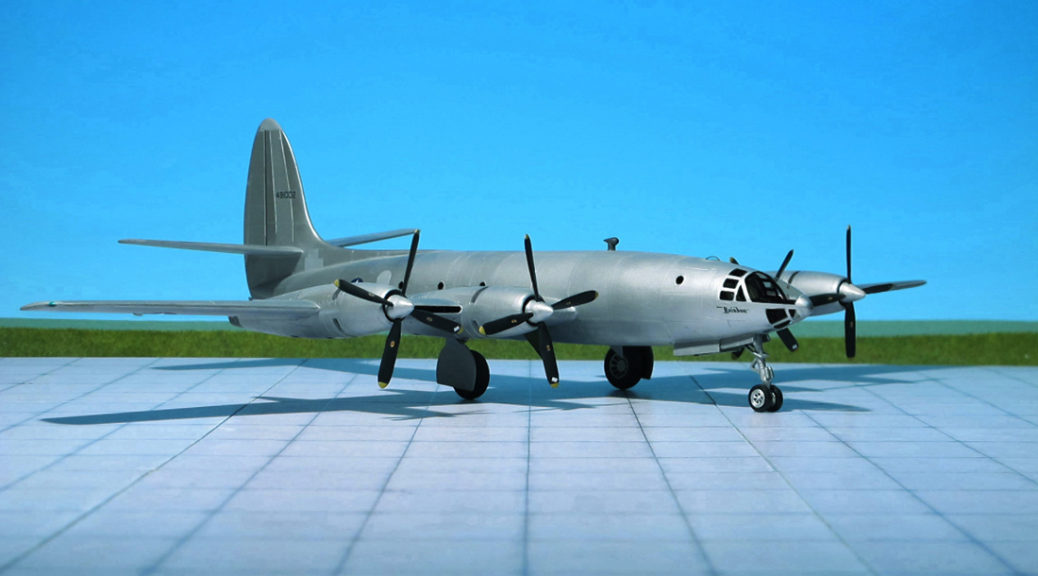
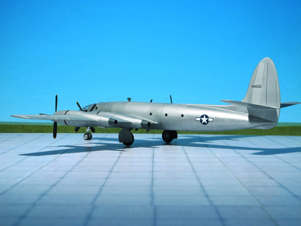
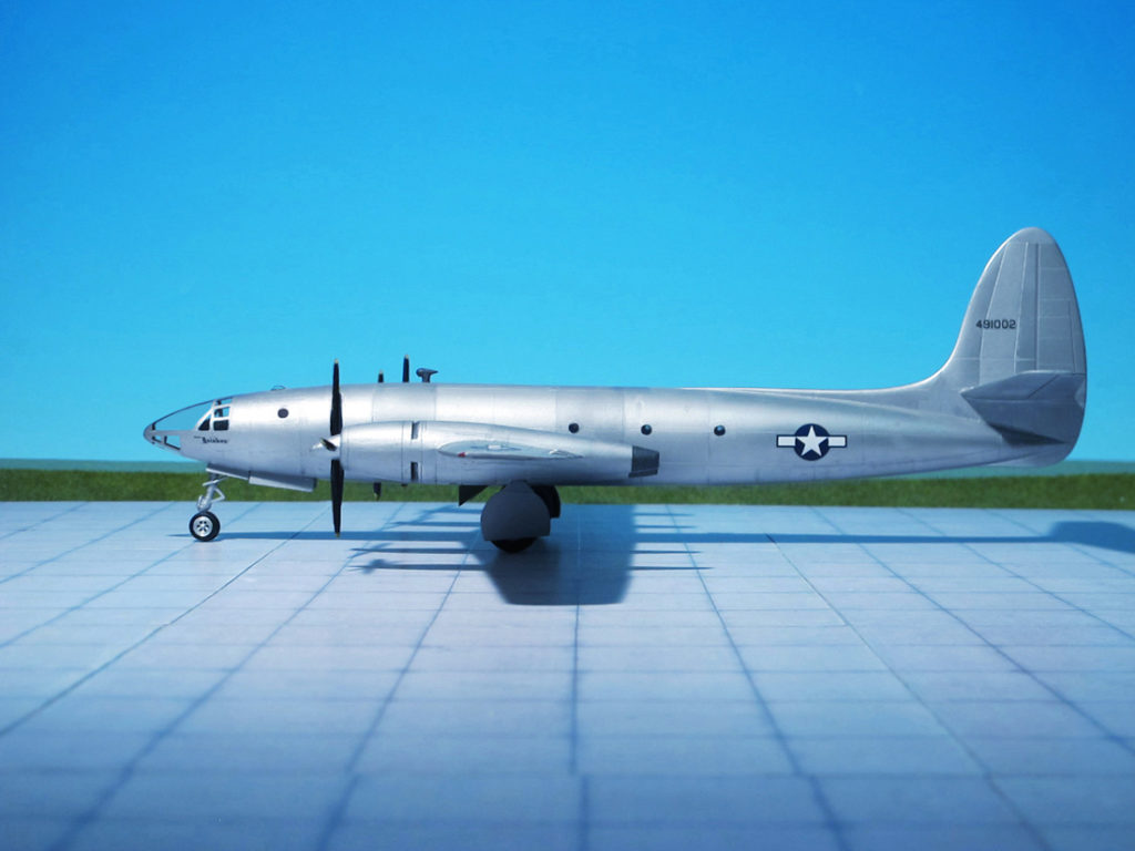
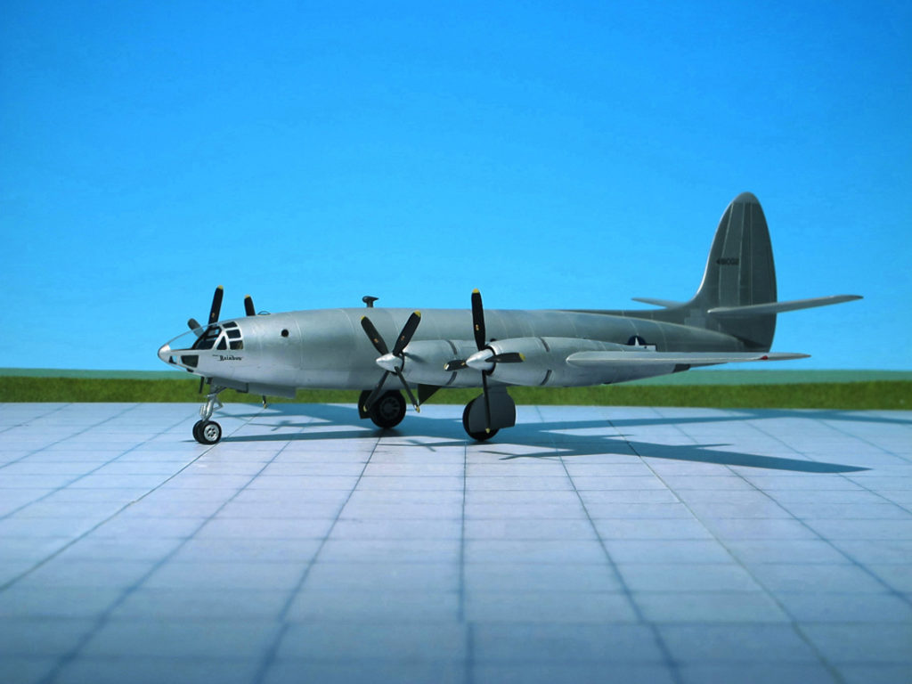
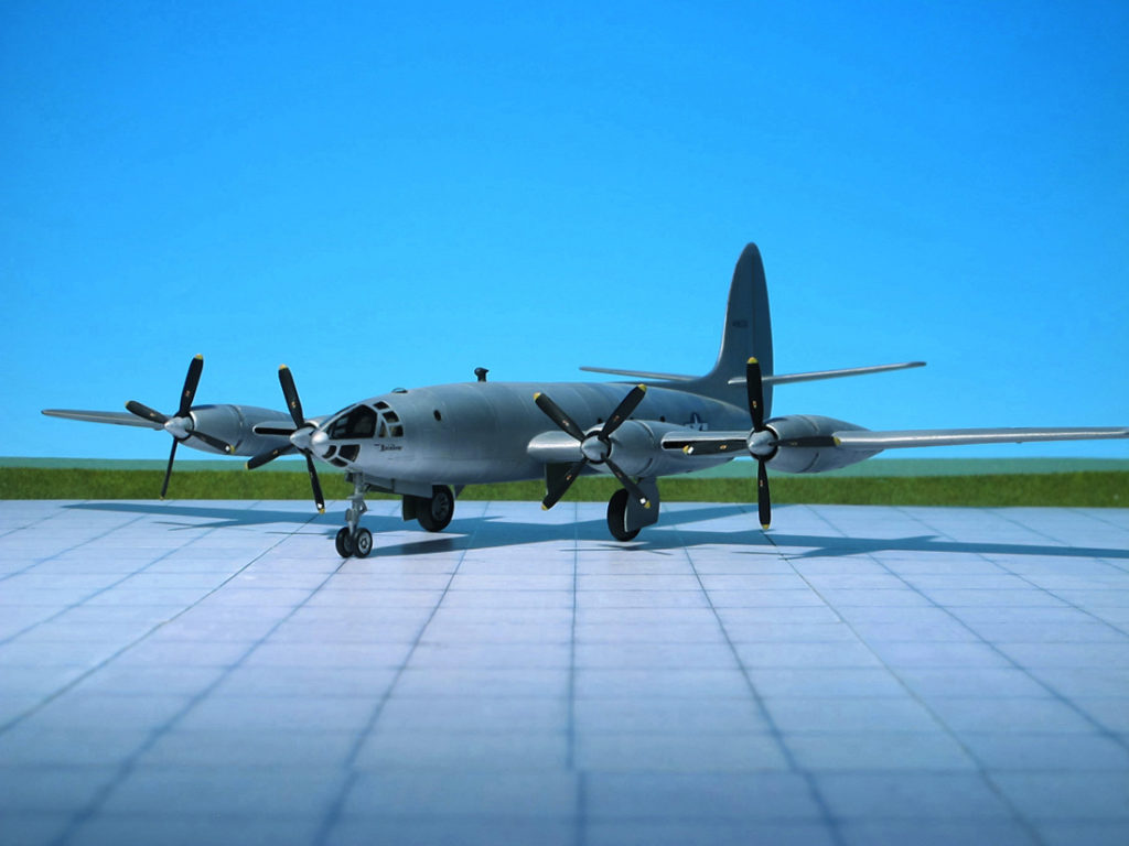
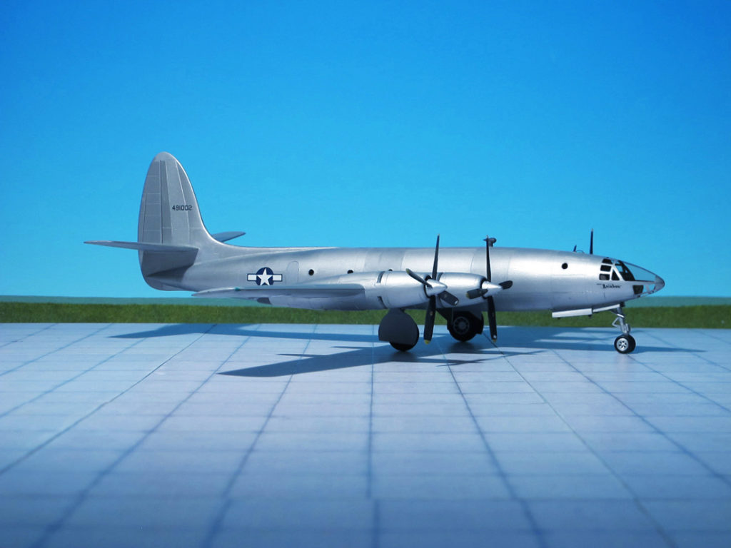
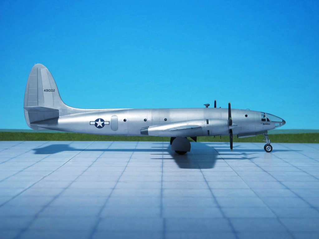
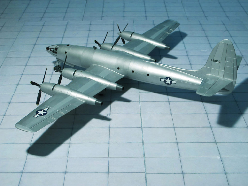
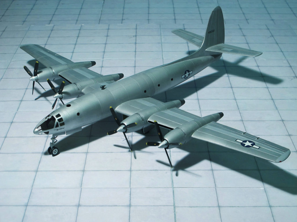
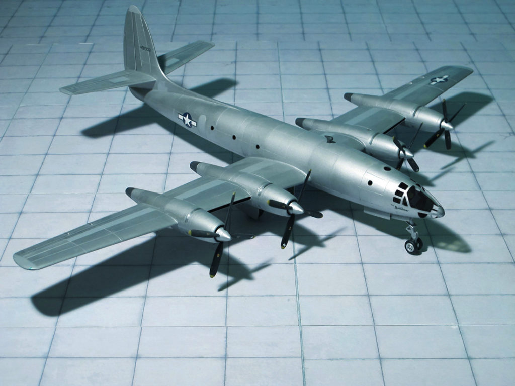
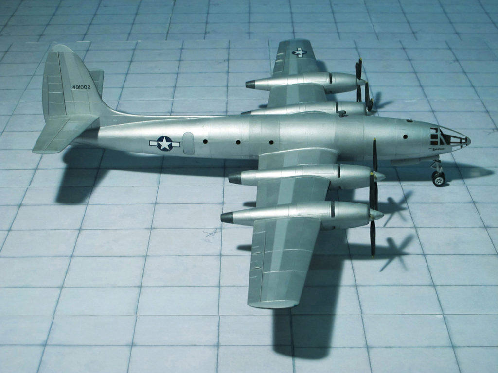
POWER PLANT: Four Pratt & Whitney R-4360-31 “Wasp Major” radial engines, rated at 3,250 hp each
PERFORMANCE: 470 mph
COMMENT: The Republic XF-12 “Rainbow” was an American four-engine, all-metal reconnaissance aircraft designed by the Republic Aviation Company in the late 1940s. The aircraft was designed with maximum aerodynamic efficiency in mind. The XF-12 was referred to as an aircraft that was “flying on all fours” meaning: four engines, 400 mph cruise, 4,000 miles range, at 40,000 feet. It is still the fastest piston-engined airplane of this size, exceeding by some 50 mph the Boeing XB-39 of 1944. Although highly innovative, the postwar XF-12 “Rainbow” had to compete against more modern turbojet engine technology, and did not enter production.
In August 1943, U.S. President Franklin D. Roosevelt’s son, Colonel Elliot Roosevelt, commander of the F-5 (modified P-38) “recon” unit, recommended the acquisition of a dedicated high-performance photo reconnaissance aircraft, capable of providing pre-strike target acquisition and photo interpretation. Followed by additional overflights to provide post-strike analysis of their subsequent destruction, this would give commanders the ability to make pivotal strategic decisions and set up subsequent raids. The XF-12 “Rainbow” was Republic Aviation’s attempt to meet those goals. Its primary competition during this time was the Hughes XF-11. Both were introduced at the same time, and both were powered by the new Pratt & Whitney R-4360. The XF-12’s first flight was made on 4 February 1946. During the XF-12’s subsequent flight testing and development period, it demonstrated the capability of operating at 45,000 feet, at a speed of 470 mph, over a range of 4,500 mi, so it met and exceeded the design goals for which it had been designed. Neither the XF-11 nor the XF-12 was purchased in any quantity by the U.S. Army Air Forces (two each), as their need evaporated after hostilities ended in World War II.
When the XF-12 was modified with increased “all weather” equipment and outfitted with its new engines capable of providing short burst of extra power, it suddenly assumed tremendous importance in the eyes of both the U.S. Air Force and the State Department. As a potent intelligence weapon, the XF-12 had the ability to obtain photographs both in daylight and under conditions of restricted visibility at high altitudes over long ranges and with great speed. In theory, operating from northern bases (Alaska and Canada), this “flying photo laboratory” was capable of mapping broad stretches of territory in the Arctic regions performing reconnaissance with near-invulnerability.[4]
Low drag was a primary consideration throughout the design of the XF-12. Many of its features were taken directly from Republic’s considerable experience with fighter plane design. In an extremely rare case of design direction, absolutely no compromise with aerodynamics was made in the shape of its fuselage, the sharp nose and cylindrical cigar shape of the XF-12 fulfilled a designer’s dream of a no compromise design with aerodynamic considerations.
To fulfill its reconnaissance role, the XF-12 contained three separate photographic compartments aft of the wing. One vertical, one split vertical, and one trimetrogon each using a six-inch Fairchild K-17 camera. For night reconnaissance missions, the XF-12 had a large hold in the belly which accommodated 18 high-intensity photo-flash bombs; these were ejected over the target area. All of the bays were equipped with electrically operated, inward retracting doors (again designed for maximum aerodynamic cleanliness). The camera lenses were electrically heated to eliminate distortion. All of this combined to allow full photo operations during high speed flights. The XF-12 also carried a variety of photographic equipment, including complete darkroom facilities to permit the development and printing of films in flight. This was augmented by adjustable storage racks, able to handle any size film containers and additional photo equipment. This allowed the Army Intelligence units to have immediate access to the intelligence the aircraft was able to collect, with no delay in processing.
The XF-12 “Rainbow” featured a wing of straight taper with squared tips and high aspect ratio for maximum efficiency. The engines featured a sliding cowl arrangement to facilitate cooling airflow instead of the normal cowl flaps, which caused too much drag. At the front of the cowls, the engines were also fitted with a two-stage “impeller fan” directly behind the propeller hub and prop spinner. This allowed the engines to be tightly cowled for aerodynamic efficiency, but still provide the cooling airflow the engines required. When the sliding cowl ring was closed (during flight), the air used for cooling the engine was ducted through the nacelle to the rear exhaust orifice for a net thrust gain, as opposed to the usual cooling drag penalty.
All of the air for the engine intakes, oil coolers and intercoolers was drawn through the front of each wing between the inboard and outboard engines. This allowed less drag than with individual intakes for each component. In addition, because the air was taken from a high-pressure area at the front of the wing, this provided a “ram air” benefit for increased power at high speeds, and more effective cooling of the oil and intercoolers. The intake portion of the wing comprised 25% of the total wingspan. They were extensively wind tunnel tested for intake efficiency and inlet contour efficiency. This cooling air, after being utilized, was ducted toward the rear of the nacelle, to provide additional net thrust. The entire engine nacelle was the length of a Republic P-47 “Thunderbolt”. Each engine featured twin General Electric turbochargers, situated at the aft end of the nacelle. All of the exhaust from the engines was ducted straight out of the back of the nacelles. This provided additional thrust. Research showed that roughly 250 equivalent horsepower was generated by each engine exhaust during high speed cruise at 40,000 ft.
The original design of the XF-12 called for contra-rotating propellers, similar to those used on the original XF-11. However, due to the added complexity and reliability issues, the propellers were never installed. They would have been twin three-bladed propellers (rotating in opposite directions). As it was, the aircraft used standard four-bladed Curtiss Electric propellers for all flights.
Had the XF-12 “Rainbow” been available in 1944, it almost inevitably would have been ordered in quantity, and along with its civilian counterpart, the whole postwar structure of aircraft markets might have been altered. As it was, the XF-12 disappeared into oblivion, despite its graceful lines and high performance. The “Rainbow” remains the ultimate expression of multi-engine, piston-powered aircraft design. Its high speed, near-perfect streamlined form, and neatly cowled engines make it a design classic, often unappreciated, and not very well known. The XF-12 was the fastest, four engine pure piston-powered aircraft of its day, and the only one ever to exceed 450 mph in level flight. (Ref.: 24).
POWER PLANT: Six Junkers Jumo 012 turbojet engines, rated at 2,500 kp thrust each
PERFORMANCE: 578 mph
COMMENT: The Junkers EF 132 was one of the last aircraft project developments undertaken by Junkers in WWII, and was the culmination of the Junkers Ju 287 design started in 1942. The shoulder-mounted wings were swept back at a 35 degree angle and featured a small amount of anhedral. Six Junkers Jumo 012 jet engines, each of which developed 2,500 kp of thrust, were buried in the wing roots. Wind tunnel results showed the advantages of having the engines within the wing, rather than causing drag by being mounted below the wing surfaces. Several wooden mockups were built of the wing sections, in order to find the best way to mount the engines without wasting too much space while at the same time providing maintenance accessibility. The landing flaps were designed to be split flaps, and the goal was to make the gearing and operation simple. Because of the high placement of the wings to the fuselage, an unbroken bomb bay of 12 meters could be utilized in the center fuselage. The tail plane was also swept back and the EF 132 had a normal vertical fin and rudder. An interesting landing gear arrangement was planned, that consisted of a nose wheel, two tandem main wheels beneath the center rear fuselage, and outrigger-type wheels under each outer wing. A fully glazed, pressurized cockpit located in the extreme fuselage nose held a crew of five. Armament consisted of two twin 20mm cannon turrets (one located aft of the cockpit, the other beneath the fuselage) and a tail turret containing another twin 20mm cannon. All of the defensive armaments were remotely controlled from the cockpit, and a bomb load of 4000-5000 kg was envisioned to be carried.
A wind tunnel model was tested in early 1945, and a 1:1 scale wooden mockup was also built at the Dessau Junkers facility to test the placement of various components, and also to check different air intake openings in the wing leading edge for the turbojet engines. The development stage had progressed far when the Soviets overran the Dessau complex and took possession of all of the Ju 287 and Junkers EF 131 and Junkers EF132 designs and components. The Soviets gave its approval for the bombed out Junkers Dessau factory to be partially rebuilt, the wind tunnels repaired and the turbojet engine test and manufacturing facilities to be put back into operation. In October 1946, the whole complex and the German engineers were transferred to GOZ No.1 (Gosoodarstvenny Opytnyy Zavod, State Experimental Plant), at Dubna in the Soviet Union, to continue development of the EF 131 and EF 132. Design work on the EF 132 continued under Dr. B. Baade at OKB-1 (the design bureau attached to GOZ No.1), under order of Council of Ministers (COM) directive No.874-266, an unpowered example was constructed to gather additional data, but only slow progress was made before the project was terminated on June 1948, by COM directive 2058-805 (Ref.: 17. 24).
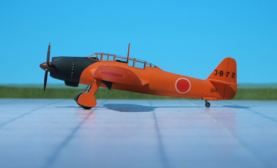
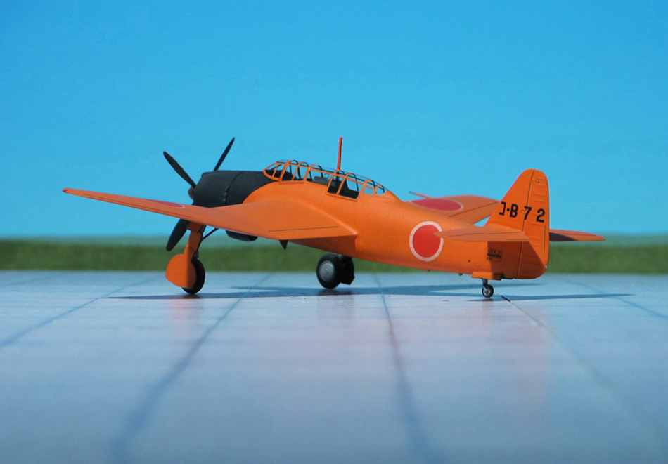
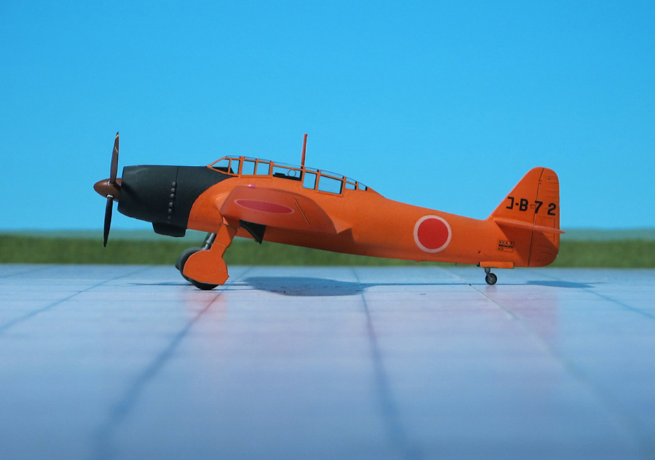
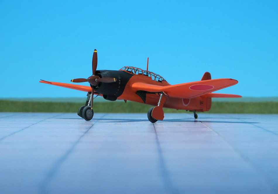
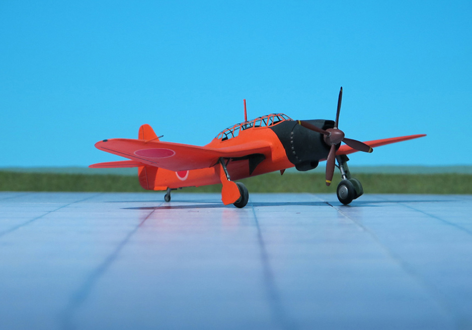
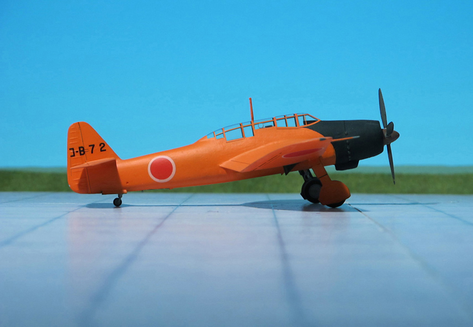
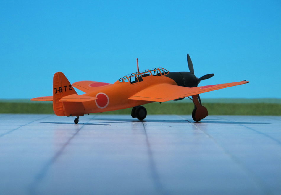
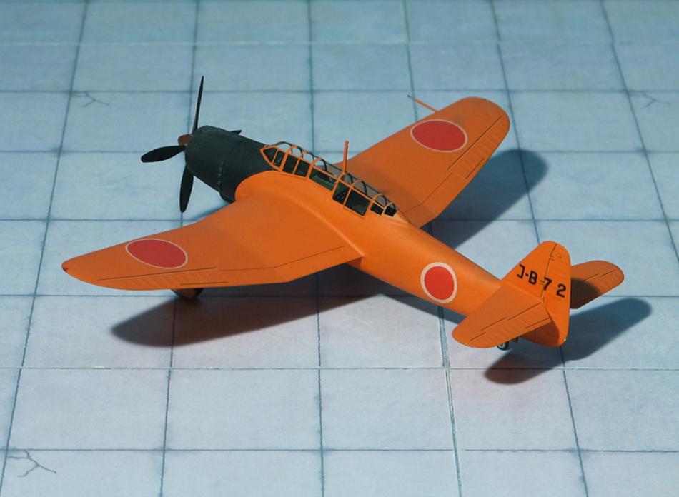
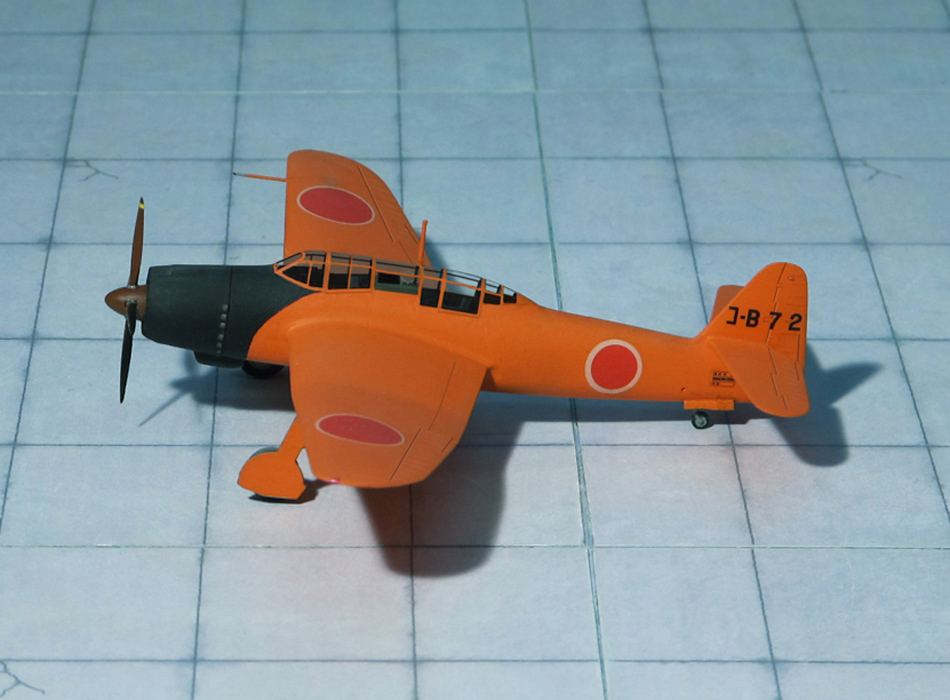
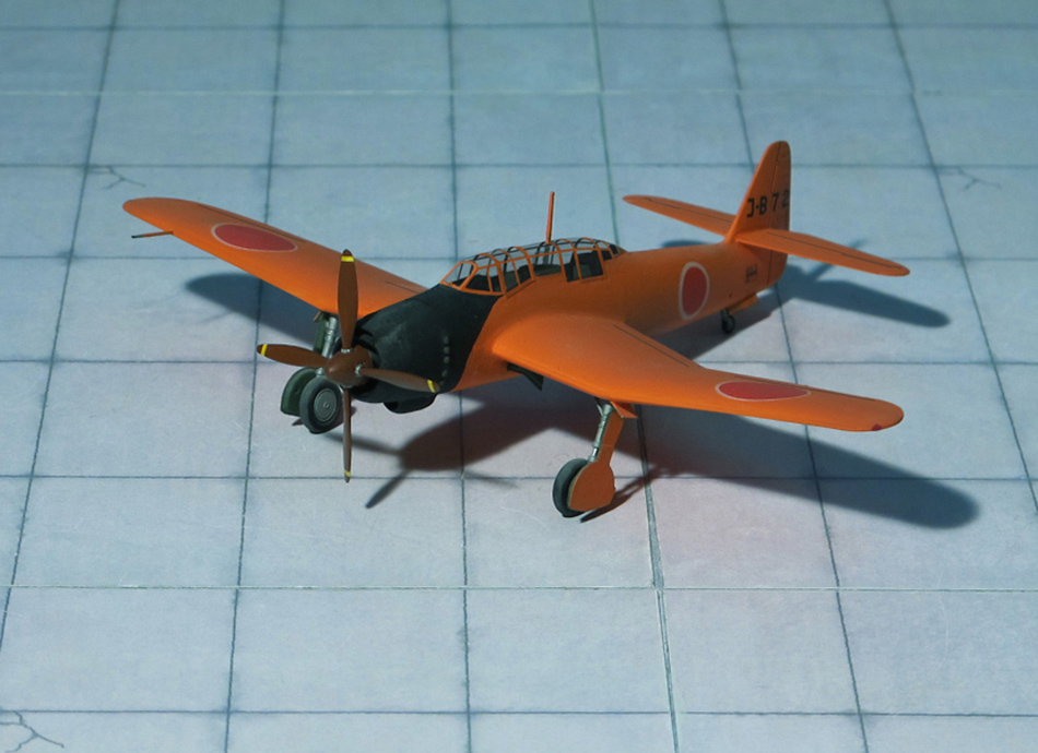
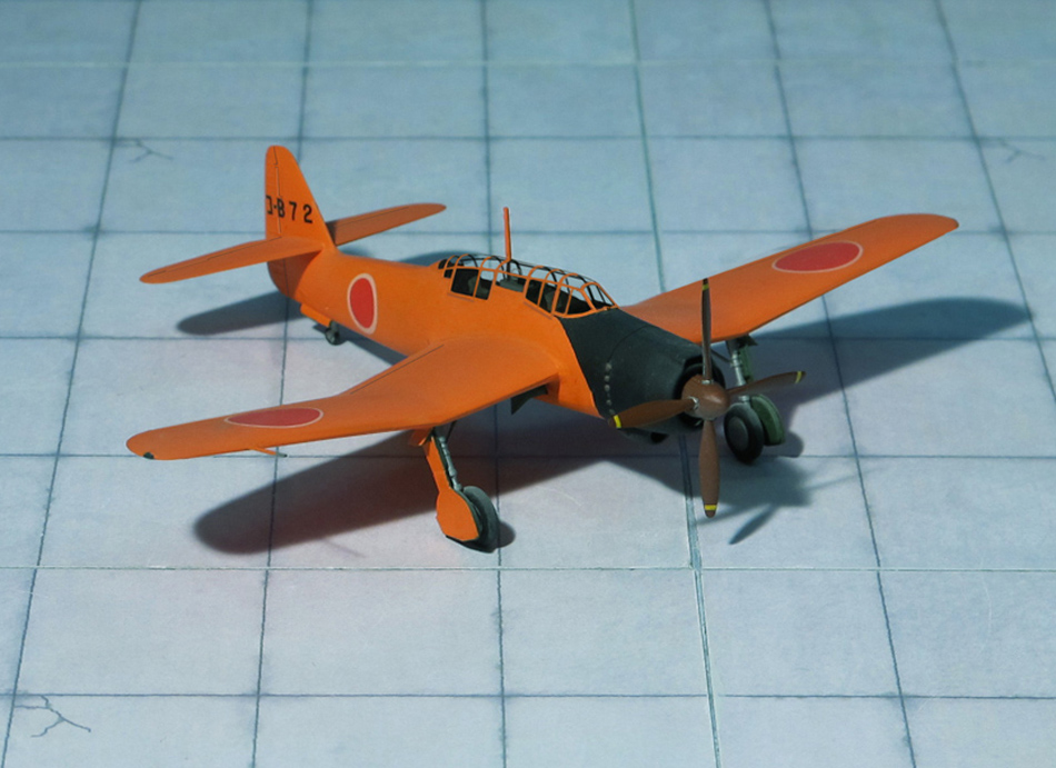
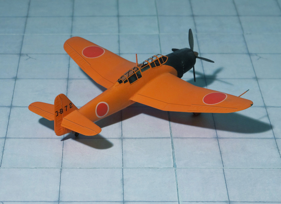
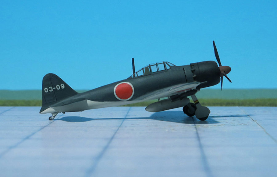
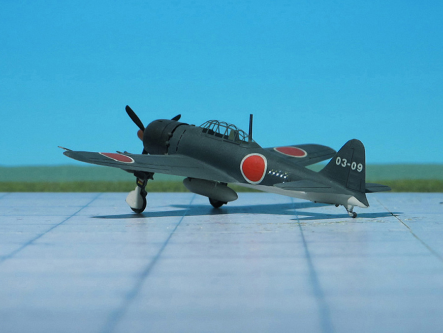
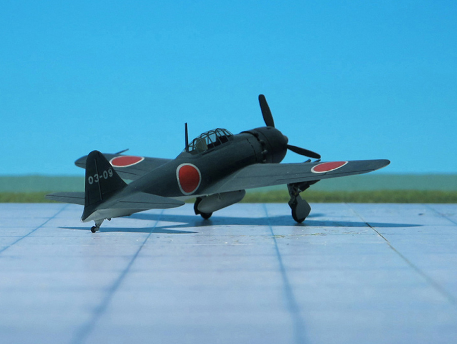
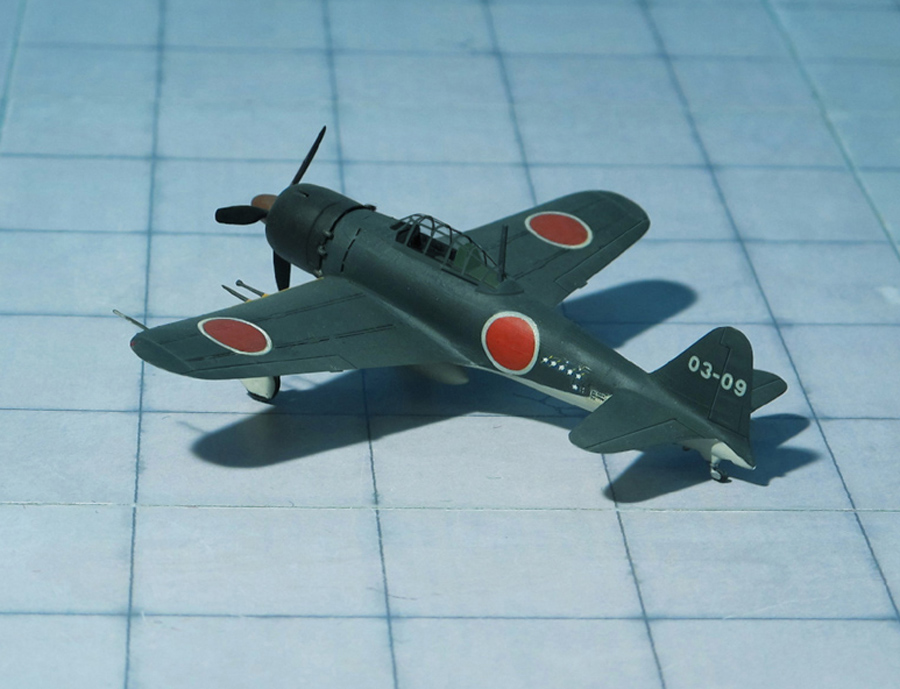
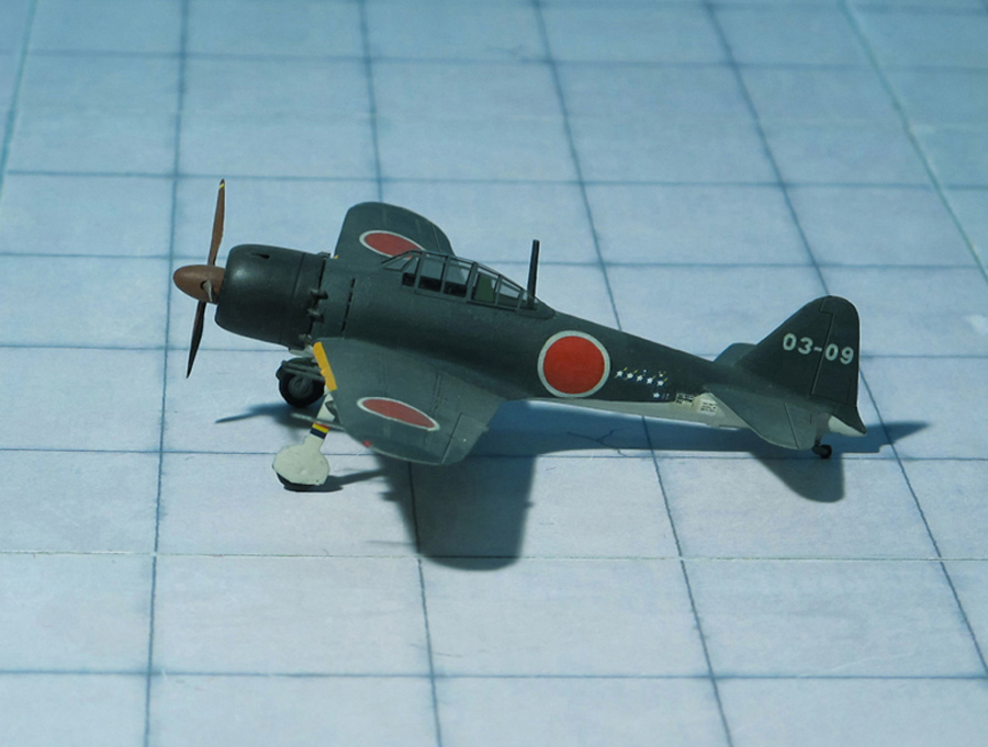
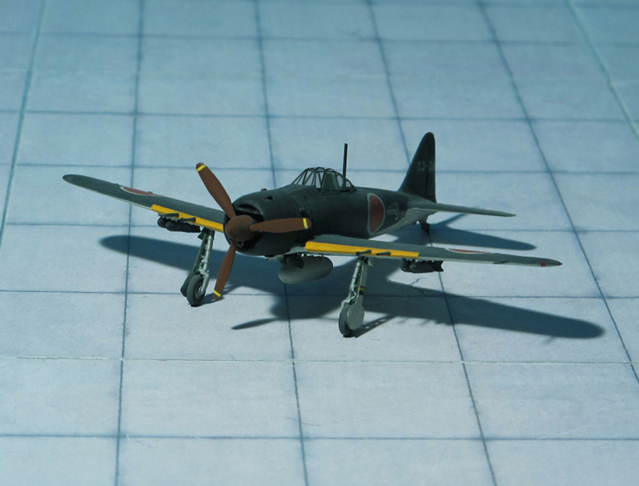
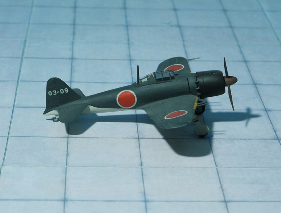
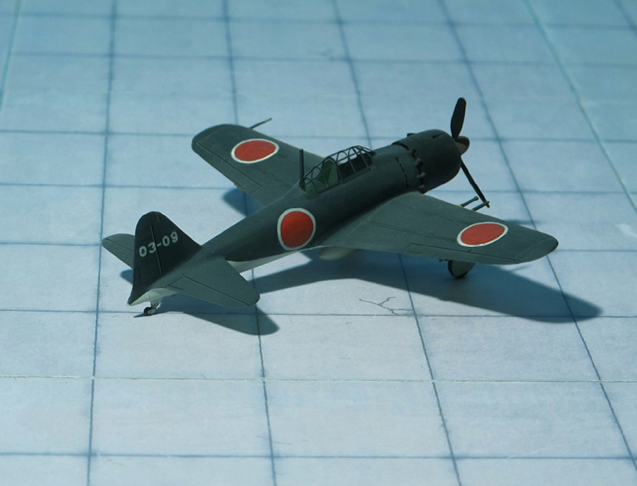
POWER PLANT: One Nakajima NK1F “Sakae 21” radial engine, rated at 1,100 hp at 9,350 ft
PERFORMANCE: 351 mph at 19,685 ft
COMMENT: The Mitsubishi A6M “Zero” was the best known Japanese warplane of WW II. A6M “Zeros” were predominantly used by the Imperial Japanese Navy Air Service (IJN) on aircraft carriers, and also by its land-based fighter units. At the start of the Pacific War in 1941, the A6M constituted about 60% of the IJN fighter force. It took part in carrier operations throughout much of the Pacific Ocean, as well as over the northeast Indian Ocean
The Mitsubishi A6M “Zero” is a long-range fighter aircraft formerly manufactured by Mitsubishi Aircraft Company. Officially, the A6M was designated as the Mitsubishi Navy Type 0 carrier fighter (“Rei-shiki-kanjō-sentōki”), or the Mitsubishi A6M “Rei-sen”. The A6M was usually referred to by its pilots as the “Reisen” (Zero fighter), “0” being the last digit of the Imperial Year 2600 (1940) when it entered service with the Imperial Navy. The official Allied reporting name was “Zeke”, although the use of the name “Zero” was later adopted by the Allies as well.
The “Zero” was considered the most capable carrier-based fighter in the world when it was introduced early in WW II, combining excellent maneuverability and very long range. The IJN also frequently used it as a land-based fighter.
With its low-wing cantilever monoplane layout, retractable, wide-set conventional landing gear and enclosed cockpit, the “Zero” was one of the most modern carrier based aircraft in the world at the time of its introduction. It had a fairly high-lift, low-speed wing with very low wing loading. This, combined with its light weight, resulted in a very low stalling speed of well below 69 mph. This was the main reason for its phenomenal maneuverability, allowing it to out-turn any Allied fighter of the time.
The “Zero” quickly gained a fearsome reputation. Thanks to a combination of unsurpassed maneuverability — even when compared to other contemporary Axis fighters — and excellent firepower, it easily disposed the motley collection of Allied aircraft sent against it in the Pacific in 1941. It proved a difficult opponent even for the British Supermarine “Spitfire”. Although not as fast as the British fighter, the “Zero” could out-turn the “Spitfire” with ease, sustain a climb at a very steep angle, and stay in the air for three times as long. In early combat operations, the “Zero” gained a legendary reputation as a dogfight achieving an outstanding kill ratio of 12 to 1, but by mid-1942 a combination of new tactics and the introduction of better equipment enabled Allied pilots to engage the “Zero” on generally equal terms. By 1943, due to inherent design weaknesses and an inability to equip it with a more powerful aircraft engine, the “Zero” gradually became less effective against newer Allied fighters. By 1944, with opposing Allied fighters approaching its levels of maneuverability and consistently exceeding its firepower, armor, and speed, the A6M had largely become outdated as a fighter aircraft. However, due to design delays and production difficulties, which hampered the introduction of newer Japanese aircraft models, the “Zero” continued to serve in a front line role until the end of the war in the Pacific. During the final phases, it was also adapted for use in Kamikaze operations.
Japan produced more “Zeros” than any other model of combat aircraft during the war. When the war in the Pacific Area of Action ended, 10,939 aircraft have been built by Mitsubishi Jukogyo K.K. and Nakajima Hikoki K.K. in four major variants A6M2, A6M3, A6M5, and A6M8, each variant including several subtypes. Nakajima built a float-plane variant, the Nakajima A6M2-N, Allied reporting name “Rufe”.
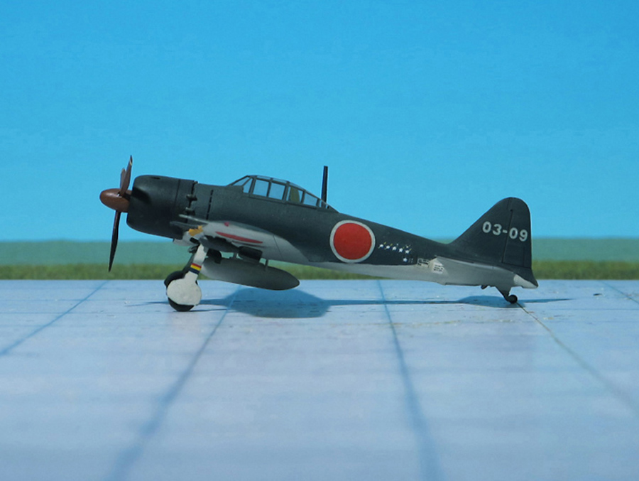
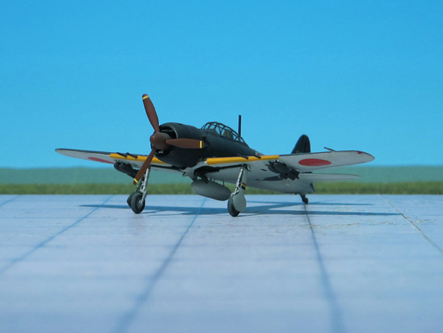
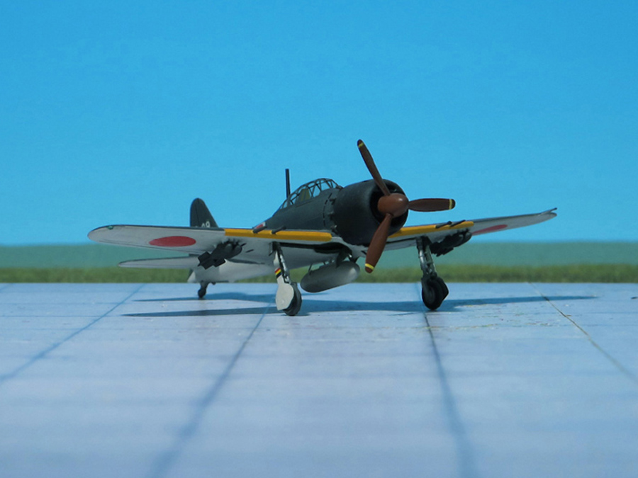
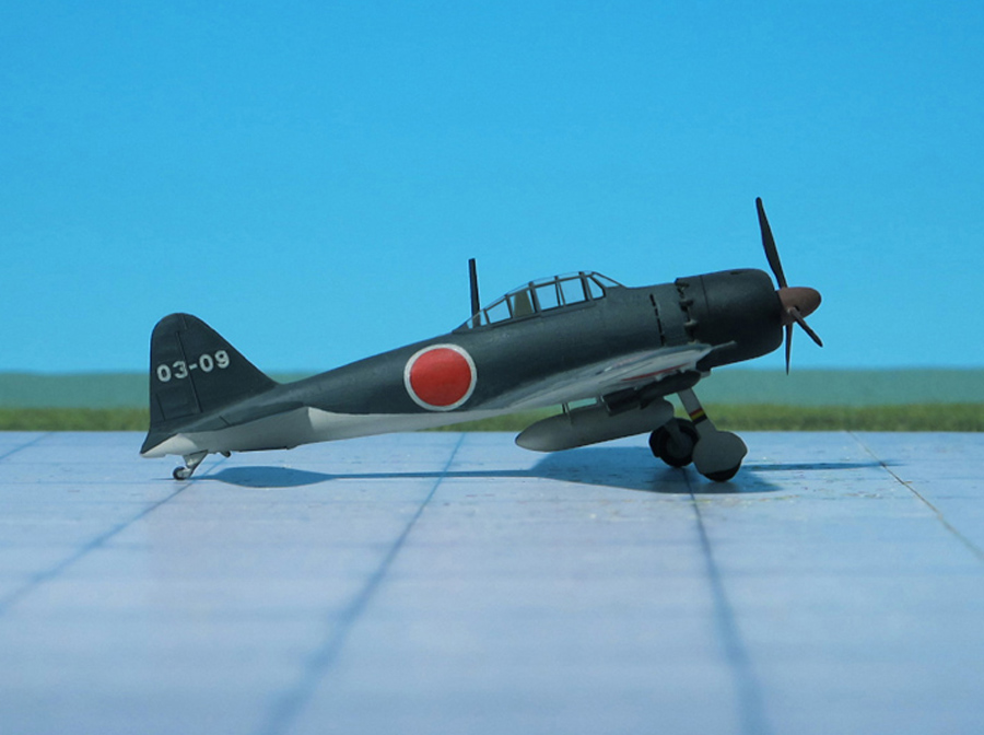
The Mitsubishi A6M5c, Model 52 Hei, featured an armament change: One 13.2 mm Type 3 machine gun was added in each wing outboard of the cannon, and the 7.7 mm gun on the left side of the cowl was deleted. Four racks for rockets or small bombs were installed outboard of the 13 mm gun in each wing. Engine changed to a Nakajima NK1F “Sakae21” although some sources state that the A6M5c had a more powerful “Sakae 31” engine. In addition, a 55 mm thick piece of armored glass was installed at the headrest and an 8 mm thick plate of armor was installed behind the seat. The mounting of the central 300 l (79 US gal) drop tank changed to a four-post design. Wing skin was thickened further. The first of this variant was completed in September 1944 (Ref.: 24).
Mitsubishi A6M5c ‘Rei-sen’ (“Zero”, “Zeke”)
Mitsubishi A6M5c ‘Rei-sen’ (“Zero”, “Zeke”)
Mitsubishi A6M5c ‘Rei-sen’ (“Zero”, “Zeke”)
Mitsubishi A6M5c ‘Rei-sen’ (“Zero”, “Zeke”)
Mitsubishi A6M5c ‘Rei-sen’ (“Zero”, “Zeke”)
Mitsubishi A6M5c ‘Rei-sen’ (“Zero”, “Zeke”)
Mitsubishi A6M5c ‘Rei-sen’ (“Zero”, “Zeke”)
Mitsubishi A6M5c ‘Rei-sen’ (“Zero”, “Zeke”)
Mitsubishi A6M5c ‘Rei-sen’ (“Zero”, “Zeke”)
Mitsubishi A6M5c ‘Rei-sen’ (“Zero”, “Zeke”)
Mitsubishi A6M5c ‘Rei-sen’ (“Zero”, “Zeke”)
Mitsubishi A6M5c ‘Rei-sen’ (“Zero”, “Zeke”)
Scale 1:72 aircraft models of World War II
Mit der weiteren Nutzung unserer Webseite erklären Sie sich damit einverstanden, dass wir Cookies verwenden um Ihnen die Nutzerfreundlichkeit dieser Webseite zu verbessern. Weitere Informationen zum Datenschutz finden Sie in unserer Datenschutzerklärung.