Category Archives: Projects

Projects

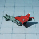
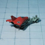
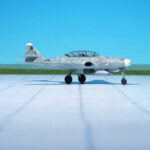
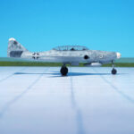
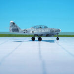
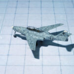
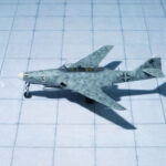
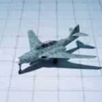
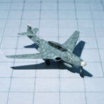
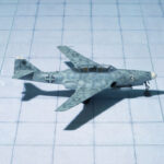
Horten Ho X, 3D-Print (my3dbase)

TYPE: Interceptor, Project

ACCOMMODATION:  Pilot only

POWER PLANT: One BMW 003 turbojet engine, rated at 950 kp thrust, later one Heinkel-Hirth HeS 011 turbojet engine, rated at 1.300 kp thrust

PERFORMANCE: 684 mph

COMMENT: Due to the rapidly deteriorating war conditions in Germany in the last months of WWII, the RLM (Reichs Luftfahrt  Ministerium, German Air Ministry) issued a specification for a fighter project that would use a minimum of strategic materials, be suitable for rapid mass production and have a performance equal to the best piston engined fighters of the time. The Volksjäger (People’s Fighter), as it became known as, was issued on September 8, 1944 to Arado, Blohm & Voss, Fiesler, Focke-Wulf, Junkers, Heinkel,  Messerschmitt and  Siebel. The new fighter also needed to weigh no more than 2000 kg have a maximum speed of 457 mph, a minimum endurance of 30 minutes, a takeoff distance of 500 m (1604′), an endurance of at least 30 minutes and it was to use the BMW 003 turbojet engine.
Although not chosen to submit a design, the Horten Brothers came up with the Ho X that met the specifications laid out by the RLM. Using a similar concept that they had been working on with their Horten IX (Ho 229) flying wing fighter,  the Ho X was to be constructed of steel pipes covered with plywood panels in the center section, with the outer sections constructed from two-ply wood beams covered in plywood. The wing featured two sweepbacks, approximately 60 degrees at the nose, tapering into a 43 degree sweepback out to the wingtips. Control was to be provided by combined ailerons and elevators at the wingtips, along with drag surfaces at the wingtips for lateral control. A single BMW 003E turbojet engine with 900 kp of thrust was housed in the rear of the aircraft, which was fed by two air intakes on either side of the cockpit.  One advantage to this design was that different jet engines could be accommodated, such as the Heinkel-Hirth He S 011 with 1300 kp of thrust, which was to be added later after its development was complete. The landing gear was to be of a tricycle arrangement and the  pilot sat in a pressurized cockpit in front of the engine compartment. Armament consisted of a single MK 108 30mm cannon or a single MK 213 30mm cannon)in the nose and two MG 131 13mm machine guns, one in each wing root.
In order to determine the center of gravity on various sweepback angles, scale models with a 3.05 meter wingspan were built. A full-sized glider was also under construction but was not completed before the war’s end. Further development would have been to add an 240 horsepower Argus As 10C piston engine in a pusher configuration and later the more powerful Heinkel-Hirth He S 011 with 1300 kp of thrust. Due to the ending of hostilities in 1945, the Horten Ho X was not completed (Ref.: 17).
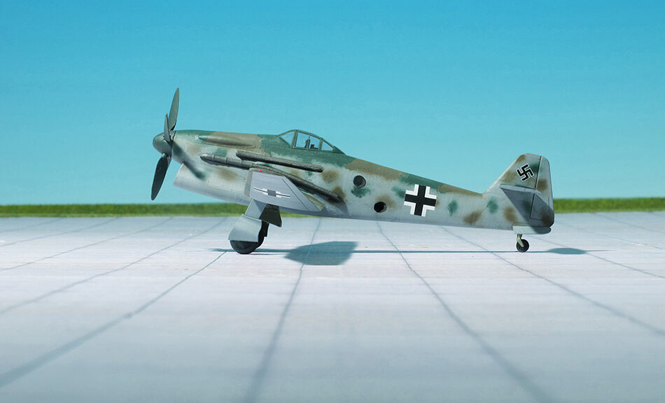
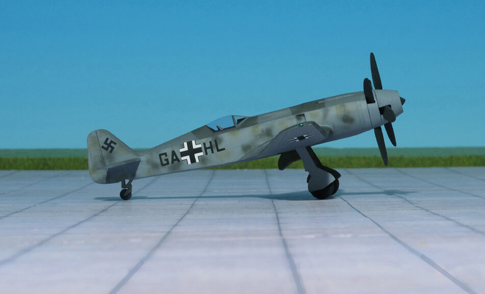
Focke-Wulf Single-Seat Fighter with BMW P.8011 (My3dbase.com)

TYPE: High-altitude Interceptor

ACCOMMODATION: Pilot in pressurized cockpit

POWER PLANT: One BMW P.8011 radial engine with two turbochargers, rated at 2.900 hp

PERFORMANCE: 451 mph in 26.215 ft

COMMENT: By the beginning of 1942, the Focke-Wulf Fw 190A was established in production and service, and most of the more serious shortcomings that has revealed themselves during the fighter’s gestation had been ironed out. A solution had still to be found out. However, the performance of the aircraft at high altitudes was inadequate. So one of the preproduction airframe was fitted with a nitrous oxide injection or GM 1 system for use above the rated altitude of the engine. The nitrous oxide, which was retained under pressure in liquid form in a tank aft of the cockpit, provided additional oxygen for the engine, but sometimes also acting as an antidetonant.
Flight testing proved disappointing. Effective combat altitude was boosted to some 26.000 ft, but insufficient nitrous oxide could be carried to increase power for more than brief periods, difficulties were experienced in lagging the pipelines, and the weight of the system, with its compressed air cylinders and heavily-lagged GM 1 tank, was almost as much as the total gun armament of the standard fighter.
Focke-Wulf was convinced that the desired performance could not be achieved with the BMW 801, and that the engine should be replaced by a liquid-cooled power plant. The design team with Prof. K. Tank favored the Daimler-Benz DB 603, but this engine was viewed with disfavor by the RLM, having been developed by Daimler-Benz without official sanction. Tank was informed that the improved performance now being sought should be achieved with developments of the BMW 801 air-cooled radial.
Meanwhile BMW was working on the BMW 802, a large air-cooled radial engine consistig of two rows of nine cylinders. It was essentially an 18-cylinder version of the 14-cylinder BMW 801. The BMW 802 emerged with an almost identical displacement to the American 18-cylinder Wright R-3350 Duplex Cyclone and somewhat larger than the British Bristol Centaurus. Although promising at first, development dragged on and the project was eventually cancelled.
Another idea to improve the performance was to bolt two BMW 801s back to back. Although seemingly a simple concept, the resulting, 83.5 litre displacement BMW 803 was in fact fantastically complicated. The power of the engine could only practically be used in extremely large propellers, or, as selected, a contra-rotating pair of propellers. This required a large gearbox on the front of the engine, which combined with the layout of the cylinders, left no room for airflow over the cylinders. This demanded the addition of liquid cooling.
Based on this concept of a twin-engine a further improvement led to the BMW P.8011. This engine was, able to produce 2.900 hp at take-off. The supercharger was replaced by two gas turbines enclosed in an aerodynamic engine cowling and driving two contra-rotating three-bladed propellers.
These engines were too heavy and powerful for the standard Focke-Wulf Fw 190 airframe. It was necessary to design a heavier airplane. The answer was a 125% scaled-up version of the Fw 190 with a wing of 42,7 ft span ad 371 sqft surface. The BMW P. 8011 was 38.7 ft long and the maximum weight was more than 11.900 lbs.
This new fighter was provided with an armored pressure cabin and used as high-altitude interceptor. Due to the war situation the project was cancelled in late 1944.
This monster fighter lacked any official designation and was only known as “Focke-Wulf Einsitzer mit BMW P.8011” (Focke-Wulf Single-seater with BMW P. 8011). By the end of 1944 in an article by General “Hap” Arnold, USAAF, published on 29 May 1944 in “Aviation News” refers it as Focke-Wulf Fw 290. But that is an error because the RLM Number “290” was given to the Junkers Ju 290 four-engine maritime control and transport aircraft (Ref.: 7, 24).

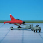
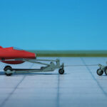
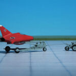
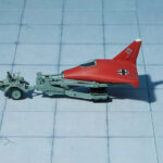
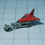
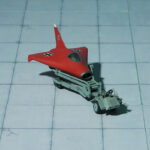
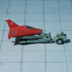
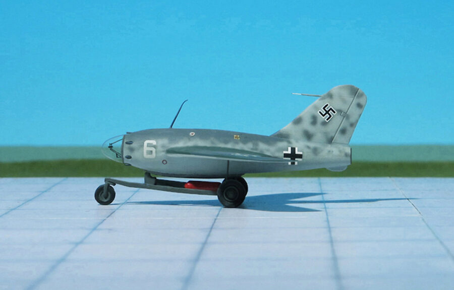
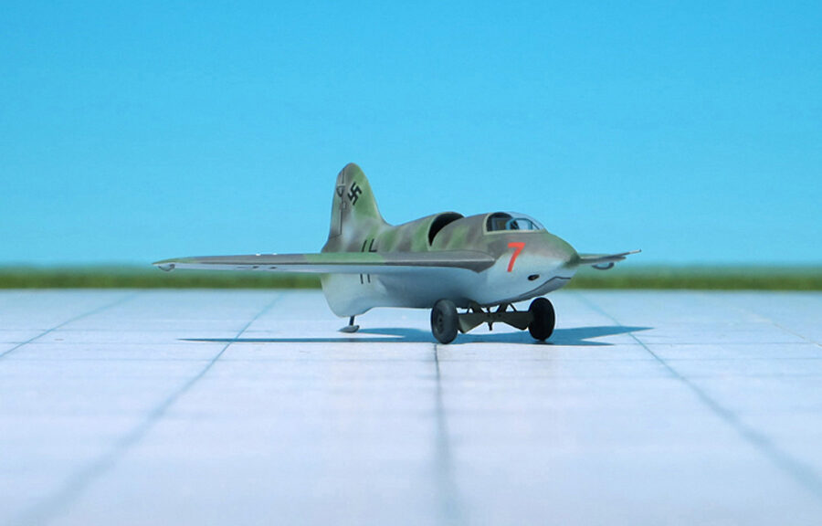
Lippisch Li P.01-117, (A+V-Models, Resin)

TYPE: Interceptor, Project

ACCOMMODATION: Pilot, in prone position

POWER PLANT: One BMW 109-510 or one Walter HWK 109-509 liquid-fuel rocket engine, each rated between 300 and 1,500 kp thrust

PERFORMANCE: 550 mph (estimated)

COMMENT: This Lippisch Li P.01-117 project dates from July and August 1941 after Alexander Lippisch and his design team moved to the Messerschmitt A.G. in Augsburg in early 1939. At that time a trio of Lippisch Li  P. 01 designs were conceptualized within three weeks – the P.01-117 on July 22, the P.01-118 on August 3 and the P.01-119 on August 4.
The first design P.01-117 featured a cockpit where the pilot laid on a couch, chin up and head forward, the second boasted a novel tilting seat arrangement to improve the pilot’s visibility during a steep near-vertical climb, and the third had a pressure cabin for high altitude operations. Each of them was to be powered by a BMW or Walter HWK rocket engine but only the P.01-118 also had a second rocket engine to provide greater endurance for level flight. From this point on, all mention of the P.01 ceased and the project continued as the Messerschmitt Me 263.
The Lippisch Li P.01-117 was a tailless aircraft, with a swept wing at approximately 35 degrees. The overall plan resembled the later Messerschmitt  Me 163 “Komet” rocket-powered fighter. The fuselage held the fuel tanks and a rocket engine was mounted in the rear fuselage. A pressurized cockpit was located in the aircraft’s extreme nose, and the pilot faced the front in a prone position and looked out through a blister of bulletproof glass. Up to six MG 151/20 20mm cannon were mounted around the nose of this aircraft. Take-off was accomplished by means of a releasable trolley, sometimes additionally boosted by two solid fuelled Schmidding 109-563 take-off rockets with 500 kp thrust each. Additional jettisonable solid-fuelled rockets could be attached to the fuselage. Landing was to be accomplished on a retractable skid, as was later done on the Messerschmitt Me 163. This design went no further than the preliminary design phase, but the Messerschmitt Me 163 went into production and was used operationally by the Luftwaffe (Ref.: 20).

Lippisch P.01-115, (Unicraft Models, Resin)

TYPE: Interceptor, Project

ACCOMMODATION: Pilot only

POWER PLANT: One BMW P-3304/109-002 turbojet engine and an undetermined Walter rocket engine, thrust of each engine unknown

PERFORMANCE: No data available

COMMENT: The Lippisch Li P.01-115 was another design under the Li P.01 series, all designed by Alexander Lippisch and his team while at Messerschmitt A.G.
Dated July 2, 1941, the Li P.01-115 had a similar plan form to the others in the P.01 series (which were similar to the Messerschmitt Me 163 rocket fighter). The fuselage held the armament, fuel and power plants. This was one of the first designs to feature a dual powered fighter. A small BMW P-3304/109-002 turbojet engine was located in the upper rear fuselage and was fed by an air intake on top of the fuselage. In addition, a BMW 109-510 rocket engine was mounted beneath the turbojet and provided takeoff and perhaps emergency power. The wings were swept back at 27 degrees, and only a single vertical tail and rudder was to be fitted. In this tailless configuration, the pilot sat in a cockpit in the front of the plane.  For take-off, a pair of wheels, each mounted onto the ends of a specially designed cross-axle, were needed due to the weight of the fuel, but the wheels, forming a take-off dolly under the landing skid, were released shortly after take-off. and landing was accomplished on a retractable skid. Two forward-firing fixed MG 151 15mm cannon located in the forward lower fuselage comprised the armament.
As with other designs in the Lippisch P.01 series, this design went no further than the drawing board stage. All work was later devoted to the Messerschmitt Me 163 “Komet” and later variant rocket fighters (Ref.: 20).

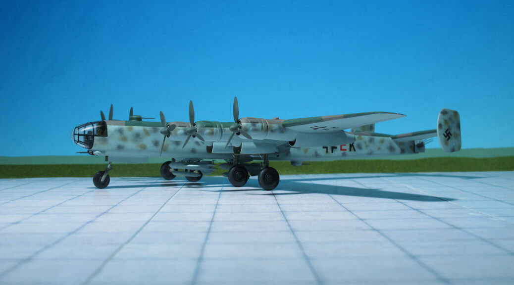
Focke-Wulf Ta 400, (Antares Models, Resin)

TYPE: Heavy bomber, Long-range reconnaissance aircraft

ACCOMMODATION: Crew of nine

POWER PLANT: Six BMW 801D radial engines, rated at 1,700 hp each plus two Junkers Jumo 004 turbojet engines, rated at 900 kp thrust each

PERFORMANCE: 450 mph (estimated)

COMMENT: The Focke-Wulf Ta 400 was a large six-engined heavy bomber design developed in Nazi Germany in 1943 by Focke Wulf Aircraft Company as a serious contender for the Amerika Bomber project. One of the first aircraft to be developed from components from multiple countries, it was also one of the most advanced Focke Wulf designs of World War II, though it never progressed beyond a wind tunnel model.
In response to the RLM guidelines of January 1942, Kurt Tank of the Focke-Wulf company designed the Ta 400 as a bomber and long-range reconnaissance aircraft, to be powered by six BMW 801D radial engines, to which two Junkers Jumo 004 turbojet engines were later added. Design work was begun in 1943, much of it being carried out by French technicians working for Focke-Wulf at the Arsenal de l’Aéronautique at Chatillon-sous-Bagneux near Paris, with contracts for design and construction of major components being awarded to German, French, and Italian companies in an attempt to speed the process and begin construction of prototypes as soon as possible.
The Ta 400 had a shoulder-mounted wing with 4° dihedral, with a long straight center section extending to the middle engine on each wing, and highly tapered outer wing panels. It had twin vertical stabilizers mounted at the tips of the tailplane. Like the American Boeing B-29 Superfortress, the Ta 400 was to have a pressurized crew compartment and tail turret, connected by pressurized tunnel, as well as multiple remote-controlled turrets. The crew was to be protected by a heavy defensive armament, including ten 20 mm MG 151 cannons; and the same Hecklafette quadmount tail-turret with two MG 131 machine guns, as the later model Heinkel He 177A series aircraft and Heinkel He 177B bombers would have used. Fuel supply was to have distributed across 32 fuel tanks. Another design feature was tricycle landing gear.
The maximum bomb load was to have been 24 t. With a gross weight of 80.27 tonnes, the Ta 400 with Daimler Benz DB 603 engines was estimated to have a range of 7,500 mi in the reconnaissance role, cruising at 202 mph. The two bomber versions would have 76.07 tonnes and 80.87 tonnes gross weights with estimated ranges of 2,800 mi and 6,600 mi respectively. The projected Jumo-powered aircraft would have had a maximum range of 8,700 mi for long range reconnaissance and 8,100 mi as a bomber.
As with the Heinkel He 277 competitor for the Amerikabomber contract, no prototype of the Ta 400 was ever built  It never progressed beyond a wind tunnel model, and performance, range and dimensions here are based solely on the designers’ estimates. The master aircraft designer Ernst Heinkel himself remarked in October 1943, while both designs were still being worked on, that he thought that only the Ta 400 could be a worthy competitor to his firm’s He 277, for the Amerika Bomber competition. The Ta 400 was essentially a backup design for the Messerschmitt Me 264. As the design required more materials and labor than the Me 264, the RLM became convinced that further development of the Ta 400 was a waste, and on October 1943 notified Focke-Wulf that the program would be terminated, but the minutes of a meeting in Italy between Tank and Italian aviation industrialists on April 1944 – just two days before the entire He 277 program was also cancelled – confirmed that work on the design was still ongoing and proposed the cooperation of Italian industry in the project (Ref.: 24).

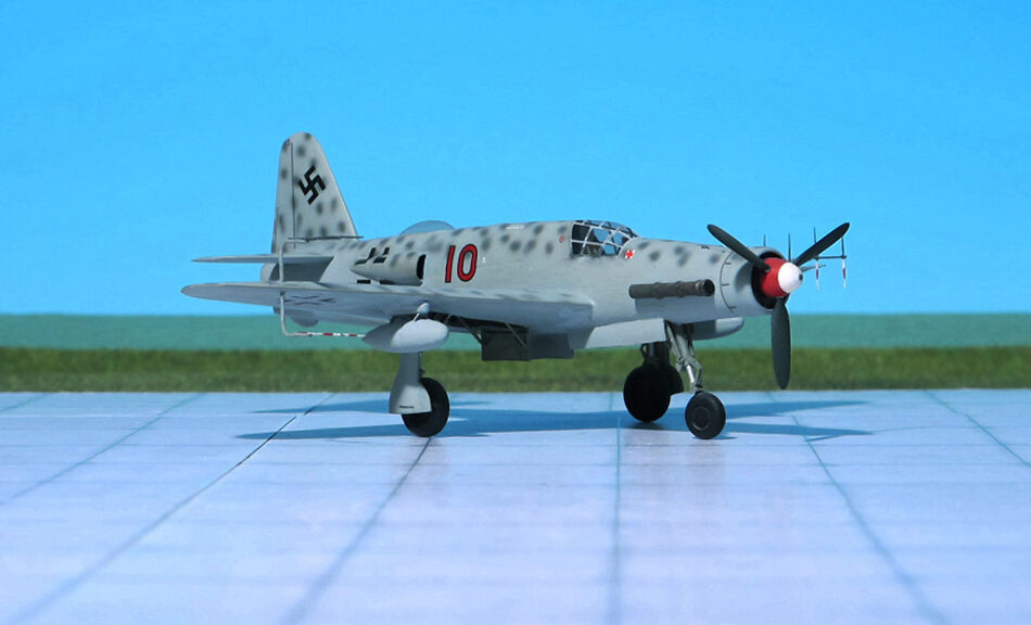
Dornier Do 435 , Dragon Models, Parts scratch-built)

Type: Heavy all-weather fighter, Project

ACCOMMODATION: Pilot and navigator/radar-operator

POWER PLANT: One Daimler-Benz DB 603G liquid-cooled engine, rated at 1,874 hp plus one Junkers Jumo 004C turbojet engine, rated at 950 kp thrust

PERFORMANCE: Not available

COMMENT: The Dornier Do 435 was a heavy all-weather fighter  projected by the Dornier aircraft manufacturer for the German Luftwaffe during World War II. The design based on the twin-engine Do 335 „Pfeil“ (Arrow) heavy fighter, Luftwaffe‘s fastest piston-engined aircraft of World War II.
In May 1942, Dornier submitted a design Do P.231/1 for a twin-engine single-seat „Schnellbomber“-like high-speed bomber/intruder with a 1,000 kg bombload. The performance of this project was predicted to be better than other twin-engine designs due to its unique push-pull configuration and the lower aerodynamic drag of the in-line alignment of the two engines.The proposed front engine was a Daimler-Benz DB 605E and drove a puller-type propeller while the second DB 605E was located in the rear part of the fuselage and drove a pusher-propeller.
This project was selected as the winner after beating rival designs from Arado, Junkers, and Blohm & Voss. A development contract was awarded, by the RLM issuing the Dornier firm the airframe approval number 8-335, for what after many manfications would become known as the Dornier Do 335 „Pfeil“ (Arrow). In autumn 1942, Dornier was told that the Schnellbomber Do 335 was no longer required, and instead a multi-role fighter based on the same general layout would be accepted. This delayed the prototype delivery as it was modified for the new role.
The first prototype Do 335 V1 flew on 26 October 1943. However, several problems during the initial flight of the Do 335 would continue to plague the aircraft through most of its short history. On May 1944, the RLM ordered maximum priority to be given to Do 335 production. The first preproduction Do 335 (A-0s) were delivered in July 1944. But only approximately 22 preproduction aircraft were thought to have been completed and flown before the end of the war.
Early in 1943, while the first prototype of the Dornier Do 335 was under construction the Dornier design team dicussed the possibility to increase the performance of this new heavy twin-engine fighter. With the availability of the brand new incomming  turbojet engines the original Dornier project Do P. 231/1 was redesigned and had the company’s internal designation Do P.231/3.  The design was a single seat fighter aircraft with conventional empennage. The nose-mounted Daimler-Benz DB 603 piston engine remained unchanged while the rear DB 603 engine was replaced by a non specified turbojet engine. The piston engine would be used for normal flight and cruising and the turbojet added for high-speed flight.
On May 1943 Dornier submitted a further development, the single-seat  Do P.323/2. The DB 603 was replaced by a 1,874 hp DB 603G and a tail-mounted Junkers Jumo 004 delivering app. 900 kp thrust was provided. The two air intakes for the turbojet were lokated at both sides of the mid fuselage. The air-flow duct was later positioned on the rear back of the fuselage (project Do P.232/3). While the development made progress the RLM decided to convert the design to a night-/bad weather fighter. The air-ducts were relocated to the fuselage sides and a navigator/radar-operator was seated in between on the upper surface in a glass-covered cockpit. A FuG 220 “Lichtenstein SN-2” radar with “Hirschgeweih” (Stag’s Antlers) aerial array was provided. The airframe was designated Dornier Do 435 and was in summer 1944 in an advanced project stage. For modification as prototype the Dornier Do 335 V4 was envisaged. But in autumn 1944 the RLM decided to stop all further work on the project. Nevertheless, Allied intelligence reports from early May 1945 mention spotting a Do 435 at the Dornier factory airfield at Löwenthal (Ref.: 24).

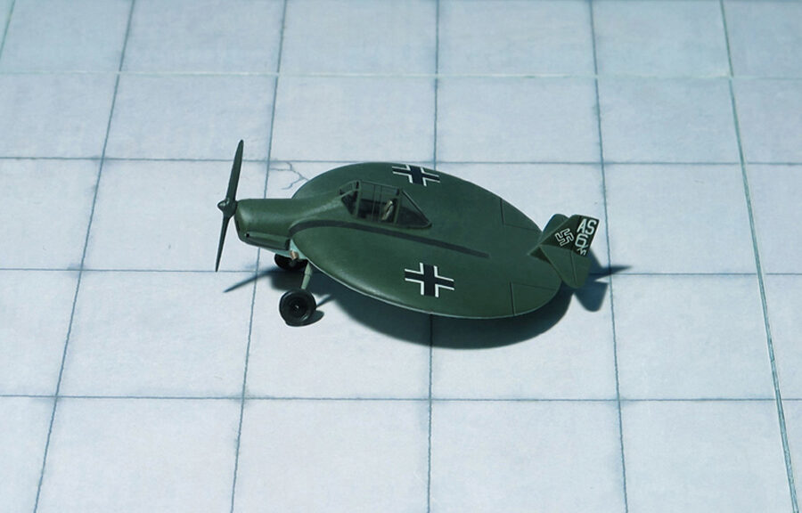
Sack AS-6 V1 (Special Hobby Models)

TYPE: Experimental circular wing aircraft

ACCOMMODATION: Pilot only

POWER PLANT: One Argus As 10C-3 liquid-cooled engine, rated at 240 hp

PERFORMANCE: Na data available

COMMENT: The Sack AS-6 was a German prototype circular-winged aircraft built privately during the Second World War. It did not see production.
The aircraft was designed by Arthur Sack, a farm owner and amateur engineer from a little town near Leipzig. In his attempts to create a circular-winged aircraft he built five model aircraft, each with little success. He entered his fifth model, with a 1.25 meter diameter wing and 1.5 horsepower engine, in a 1939 competition for remotely controlled models with combustion engines. The models were to take off and land at the same point. None of the entries managed to do so. Sack’s model was unable to take off from the ground but flew when released by hand.
At the end of 1940 Sack started design of the AS-6, a full-sized, manned aircraft and successor to the earlier models. Its wing diameter was four times larger than the last model. He built it privately in a shed at his farm, using a wood construction. The Argus As 10 engine as well as the main landing gear from a Messerschmitt Me 109 was sponsored by ATG, a company at Leipzig, that assembled Junkers bomber aircraft. In 1944 the AS-6 prototype was finished and its design documents provisionally approved. Arthur Sack enlisted the help of the chief test pilot of ATG to test the aircraft. Approximately a dozen tests revealed multiple failings, especially in the undercarriage, and managed little more than a hop off the ground. The tests continued at an airbase in Brandis by a pilot in a Messerschmitt Me 163B unit based there. As the AS-6 did not appear on an inventory of seized items when US forces captured the airbase it is assumed that the plane was destroyed to prevent capture (Ref.: 24).

It is to note that the US Navy also planned to realize a disc-shaped Short Take-off/Landing (STOL) aircraft. In the late 1930s the Vought Company was working on an experimental twin engine, circular winged aircraft, the  V-173 Flying Pancake. After successful and promising flights the US Navy placed an order for two prototypes of a new carrier-based fighter aircraft, larger, heavier and more powerful than the V-177. Two prototypes oft he Chance Vought XF5U-1 Flying Flapjack were built made only ground runs and never lifted into the air. Due tot he end of WW II and with jet aircraft coming into service, the Navy finally canceled the project in 1947. Possibly a turbojet powered variant, the Vought Jet skimmer, was on the drawing board. Exact data are not available.

Dornier Do 635 (Dragon Models, Parts scratch-built

TYPE: Long-range reconnaissance aircraft

ACCOMMODATION: Crew of two

POWER PLANT: Four Daimler-Benz DB 603E liquid-cooled engines, rated at 1,777 hp each

PERFORMANCE: 447 mph

COMMENT: The Dornier Do 635 was a WW II long-range reconnaissance aircraft of the German Luftwaffe proposed by Dornier Company, as two Dornier Do 335 fuselages joined by a common center wing section.
In 1944, designers of Dornier Flugzeugwerke proposed the RLM a long-range reconnaissance aircraft with a range of 2.480 mi under the designation Dornier Do 335Z (Z for Zwilling ; “Twin”). Similar to the Heinkel He 111Z, a combination of two Heinkel He 111 bombers joined by a common center wing section, two Dornier Do 335B fuselages were connected by a center wing section. The pilot was seated in the left fuselage, the radio operator/navigator sitting in the right fuselage. Armament was not envisaged. The RLM confirmed the design provided the range was increased to app. 3.720 mi. Further modifications changed the design from the original Do 335 into a completely new aircraft; the new RLM designation was now Dornier Do 635. Four prototypes were ordered and begin of production was planned for June 1945.
On order of the RLM and representatives of the Luftwaffe the cooperation with Dornier was cancelled and all further development was transferred to Heinkel Flugzeugwerke.
Reason might be that Heinkel’s team had much experience with the Heinkel He 111Z and its twin fuselage combination.  The designation of the project was internally changed to Heinkel He P.1070, officially Heinkel He 535 (or He 635, depending on literature). Again, profound changes were required. In order to increase range three external fuel tanks under the outer and center wings were provided, the wing span was reduced and the fuselage length was increased.
All these changes did not satisfy the RLM, so the design was revised again. The crew compartment was now solely positioned in the left fuselage and enlarged to seat three crew members: pilot, copilot and observer/navigator. Wing span was increased again, the center wing section was shortened to bring both fuselages closer together and the inner tail planes were provided as a common sector.
Meanwhile, a lot of time was wasted due to permanent changes in the requirements of the design. Finally, all further development was transferred to Junkers Flugzeugwerke. Prof. Hertel and his team refined the design once again, now under the designation Junkers Ju 635. The aim was to simplify the aircraft for easier production and an increase of range to app. 7.200 mi.
As its predecessor the Junkers design used two modified Dornier Do 335 fuselages, joined by a center wing section of constant chord, the outer wing panels were tapered back. Four Daimler-Benz DB 603E-1 engines supplied the power, one in each forward fuselage pulling and two in each rear fuselage driving a pusher propeller via a long drive shaft. Fuel was carried in ten internal wing tanks, four in the fuselages and possibly one in each fuselage bay. The port fuselage bay carried two Rb 50/30 cameras and the starboard bay contained five 60 kg marker bombs. A crew of three was envisioned, although this could be increased to four eventually. The pilot and the radio operator sat in the port fuselage and a second pilot sat in the starboard fuselage. The fourth crew member (navigator) was also to sit in the starboard fuselage. The landing gear was to consist  of two nose wheels under each fuselage nose, two main wheels which were fitted with mud guards to protect the rear radiator intakes, and a jettisonable fifth wheel located beneath the center wing, which was fitted with a parachute for recovery. The main wheels were modified from the Junkers Ju 352 transports wheels. Two Walter HWK 109-500 RATO (Rocket Assisted Take Off) units could be fitted to assist take off. No armament was included due to the fact that this was a long-range reconnaissance aircraft and thus all weight was reserved for fuel and speed.
Four prototypes and six preproduction aircraft were orderd, the first example planned to take-off on February 1945. By early 1945, wind-tunnel models had been tested and cockpit mockups had been constructed. But by February 1945 due to the worsening war situation all further work on the Junkers Ju 635 was stopped.
The model shown here is the first design of the Dornier Do 635 (Ref.: 17, 24).

Junkers Ju 488 V401 (Kora Models, Resin)

TYPE: Heavy strategic bomber

ACCOMMODATION: Crew of three

POWER PLANT: Four BMW 801TJ or BMW 802 radial engines, rated at 2,500 hp each

PERFORMANCE: 429 mph at 23,620 ft

COMMENT: The Junkers Ju 488 was Germany’s last real attempt to create a four-engined, long range bomber. In early 1944, Junkers design department at Dessau made a proposal to simply and quickly produce a heavy bomber, using a minimum of new building jigs or parts. Basically, the Ju 488 was to be constructed out of existing Junkers aircraft. The Ju 388K was to supply the pressurized crew cabin, the Ju 188E supplied the rear fuselage, the ventral pannier was to come from the Ju 88A-15 and Ju 388K series, outer wing sections from the Ju 388K and finally the entire twin fin tail section from the Ju 288C. Added to this collection were a new center fuselage section and a parallel wing center section, to carry the four engines.
The Ju 488 V401 and V402 were to be entirely of metal construction, with the exception of the ventral pannier, which was constructed of wood. The fuselage had an internal bomb bay and five fuel tanks located behind the fuselage and above the bomb bay. The mid-fuselage mounted wing was tapered on the outer wing panels and featured a two spar, all metal construction, with a total of eight fuel tanks within the wing. Four BMW 801TJ 14 cylinder radial engines (driving four bladed propellers) were mounted in individual nacelles, with each nacelle containing a single main landing gear leg, which retracted to the rear. One interesting design workaround was that the outer engines had to be mounted lower on the wing, because the wing dihedral would have left the landing gear a little short from reaching the ground. No defensive armament was to be fitted to either the V401 or V402.
Proceeding in parallel with the first two 488 prototypes’ construction, a new, larger aircraft was being designed. This was to be the production model Junkers Ju 488A, and four prototypes (V403-406) were ordered. This new version deleted the wooden ventral pannier and the wing was moved further to the rear. The BMW 801TJs were to be replaced by four Jumo 222A-3 or B-3 liquid cooled 24 cylinder four row radial engines. Perhaps the biggest change was the lengthened fuselage, which was to use a welded steel tube construction with a sheet metal covering towards the front portion of the aircraft, and a fabric covering for the rear. An extra fuel tank could now be carried within the fuselage, for a maximum total of 15.066 liters (3.980 gallons). Defensive armament consisted of a remote controlled tail barbette with two MG 131 13 mm machine guns and a single remote controlled dorsal turret with two MG 151 20 mm cannon, both controlled from the pressurized cockpit via a periscope.
Work was begun on the Junkers Ju 488 V401 and V402 prototypes in the former Latécoère factory at Toulouse in early 1944. The plan was for the fuselage and the new wing center section to be built in Toulouse, all other components would come from the Junkers Dessau and Bernburg factories. It was hoped to have the Ju 488 in operational service by mid-1945. Construction was well advanced when the decision was made in July of 1944 to move the existing work done to date to Bernburg by train, due to the rapidly advancing Allied invasion forces. On the night of July 1944, resistance fighters succeeded in destroying the Ju 488 V401 fuselage and center wing section to the extent they could not be salvaged. After the last of the German forces evacuated the city in late August 1944, the V402 forward fuselage section was found covered and abandoned on a railway siding. No record seems to exist as to the final disposition of this last remaining Ju 488 piece. The entire Ju 488 program was discontinued in November 1944, when it was realized that a new large bomber aircraft was not needed at this stage in the war. An attempt was made to offer the Ju 488 design to the Japanese, but they were not interested (Ref.: 17).
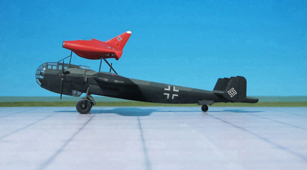
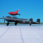
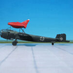
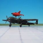
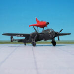
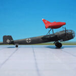
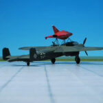
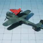
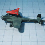
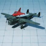
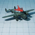
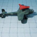
Arado Ar 234C-2 with Fieseler Fi 103 (V-1), (Dragon Models)

ARADO Ar 234C-2 BLITZ

TYPE: Turbojet driven bomber, Mistel (Mistletoe) component
ACCOMMODATION: Pilot only
POWER PLANT: Four BMW 003A-2 turbojet engines, rated at 800 kp thrust each
PERFORMANCE: 460 mph at 20,000 ft
COMMENT: The Arado Ar 234 Blitz (Lightning) was the world’s first operational turbojet-powered bomber, built by the German Arado company during World War II.
Produced in limited numbers it was used almost entirely for aerial reconnaissance. In its few uses as a bomber it proved to be nearly impossible to intercept. It was the last German Luftwaffe aircraft to fly over the UK during the war, in April 1945
The Ar 234 was built in various versions: Ar 234A with two turbojet engines, Ar 234B with two turbojet engines or for engines in separat nacelles and Ar 234C with four engines mounted in a  pair of twin-engine nacelles and a purely rocket-engine-driven Ar 234R. Of each of these various versions sub-types were built or planned.
The Arado Ar 234C was equipped with four lighter weight BMW 003A turbojet engines mounted in a pair of twin-engine nacelles based on basis of the eighth prototype. The primary reason for changing the engienes was to free up the Junkers Jumo 004 turbojets for use by the Messerschmitt Me 262, but the change improved overall thrust to nearly 3.2 tonnes with all four BMW turbojets at full take-off power, especially useful for take-off and climb-to-altitude performance. An improved cockpit design, with a slightly bulged outline for the upper contour integrating a swept-back fairing for the periscope, used a simplified window design with fewer glazed panels for ease of production. The four BMW jet engines gave about 20% greater airspeed than the Ar 234B series airframes, and the faster climb to altitude meant more efficient flight and increased range.
Although an operational test squadron was being prepared, only 14 C-series airframes had been completed by the end of the war, of which fewer than half had engines. Some were found at the end of the war sitting in the open, complete but for empty engine nacelles.Comprehensive flight testing of the new sub-type had yet to begin when Germany surrendered. Three basic variants of the C-series were planned for initial construction, with several more laid out as detailed proposals. Some of these would have had a pair of the higher thrust, but heavier Heinkel/Hirth HeS 011turbojet engines, while others were intended to feature swept or “crescent”-type wings.
There were plans, not put into practice, to use the Arado 234C turbojet bomber to launch V-1s either by towing them aloft or by launching them from a “piggy back” position (in the manner of the Mistel (Mistletoe), but in reverse) atop the aircraft. In the latter configuration, a pilot-controlled, hydraulically operated dorsal trapeze mechanism would elevate the missile on the trapeze’s launch cradle about 2.4 m clear of the Ar 234’s upper fuselage. This was necessary to avoid damaging the mother craft’s fuselage and tail surfaces when the pulsejet ignited, as well as to ensure a “clean” airflow for the Argus motor’s intake.

FIESELER Fi 103 V-1 FLYING BOMB

TYPE: Unmanned Flying bomb
ACCOMMODATION
: None
POWER PLANT
: One Argus As 109-014 pulsejet, rated at 330 kp thrust
PERFORMANCE: 400 mph at 3000 ft
COMMENT:
The V-1 flying bomb (Vergeltungswaffe 1, Vengeance Weapon 1) was an early cruise missle and the only production aircraft to use a pulsejet for power. Its official RLM (Reichsluftwsffenministerium, Reich Aviation ministry) designation was Fi 103 was also known to the Allies as the buzz bomb or doodlebug and in Germany as Kirschkern (cherry stone) or Maikäfer (maybug).The V-1 was deployed for the terror bombing of London. It was developed at Peenemünde Army Research Center in 1939 by the German Luftwaffe at the beginning of the WW II. Because of its limited range, the thousands of V-1 missiles launched into England were fired from launch favilities along the French and Dutch coasts.
The V-1 was designed with a fuselage constructed mainly of welded sheet steel and wings built of plywood. The simple Schmidt/Argus-built pulsejet engine pulsed 50 times per second, and the characteristic buzzing sound gave rise to the colloquial names buzz bomb” or doodlebug.
The Argus pulsejet‘s major components included the nacelle, fuel jets, flap valve grid, mixing chamber Venturi, tail pipe and spark plug. Compressed air forced gasoline from the 640 l fuel tank through the fuel jets, consisting of three banks of atomizers with three nozzles each. Argus’ pressurized fuel system negated the need for a fuel pump.  These nine atomizing nozzles were in front of the air inlet valve system where it mixed with air before entering the chamber. A throttle valve, connected to altitude and ram pressure instruments, controlled fuel flow. Schmidt’s spring-controlled flap valve system provided an efficient straight path for incoming air. The flaps momentarily closed after each explosion, the resultant gas compressed in the Venturi chamber, and its tapered portion accelerated the exhaust gases creating thrust. The operation proceeded at a rate of 42 cycles per second. The engine made its first flight aboard a Gotha Go 145 biplane on 30 April 1941.
The V-1 guidance system used a simple autopilot developed to regulate altitude and airspeed. A pair of gyroscopes controlled yaw and pitch, while azimuth was maintained by a magnetic compass. Altitude was maintained by a barometric device.Two spherical tanks contained compressed air  that drove the gyros, operated the pneumatic servo-motors controlling the rudder and elevator, and pressurized the fuel system. The warhead consisted of 850 kg of Amatol, 52A+ high-grade blast-effective explosive with three fuses. An electrical fuse could be triggered by nose or belly impact. Another fuse was a slow-acting mechanical fuse allowing deeper penetration into the ground, regardless of the altitude. The third fuse was a delayed action fuse, set to go off two hours after launch.
Almost 30,000 V-1s were built; by March 1944, they were each produced in 350 hours (including 120 for the autopilot), at a cost of just 4% of a V-2, which delivered a comparable payload. Approximately 10,000 were fired at England; 2,419 reached London (Ref.: 7, 24).