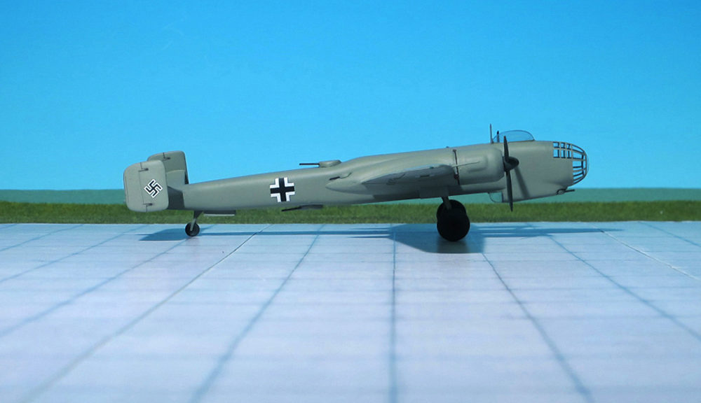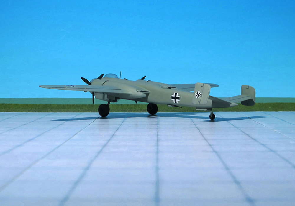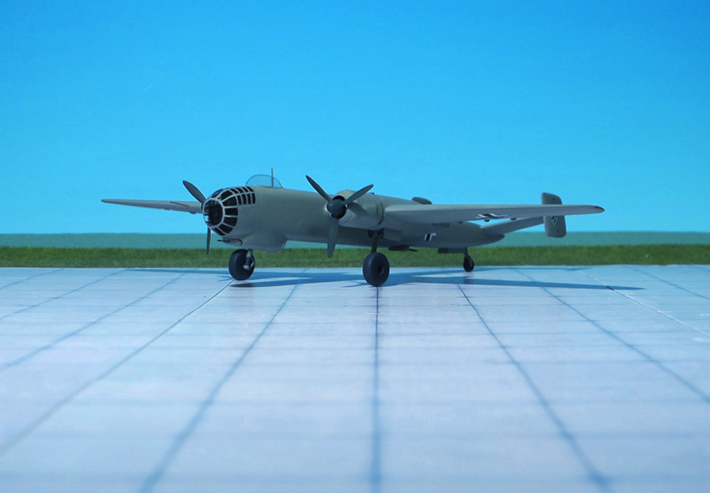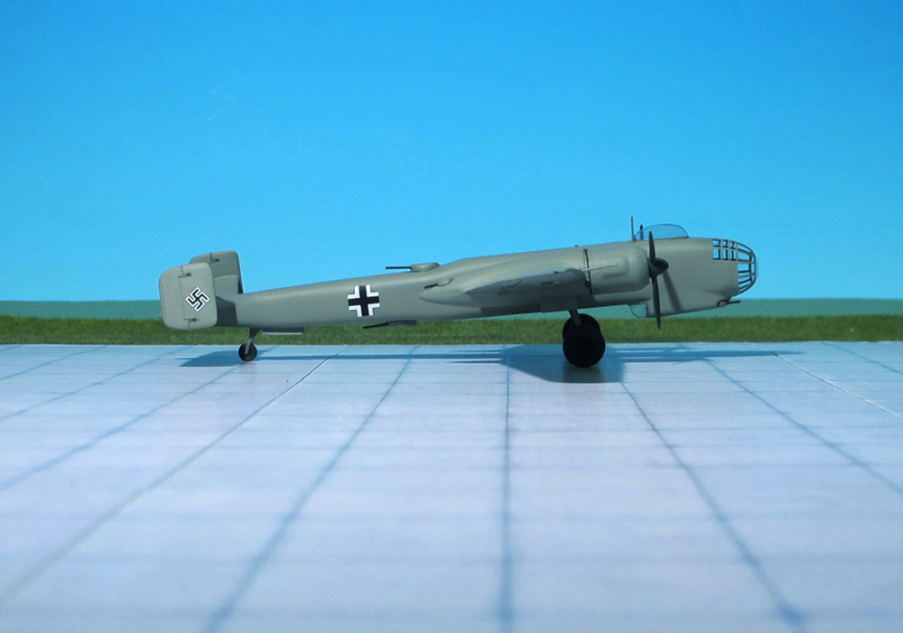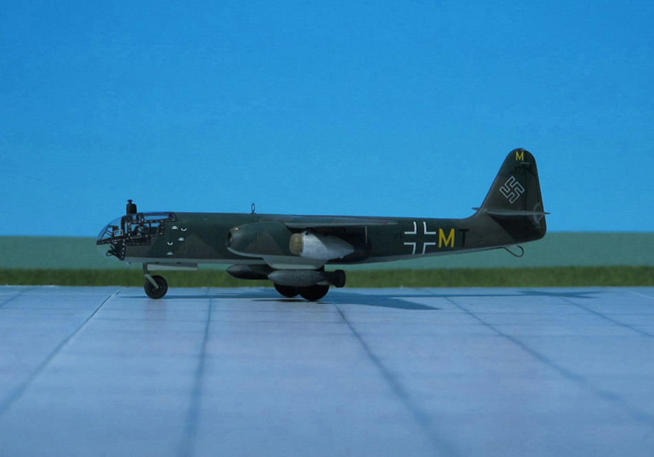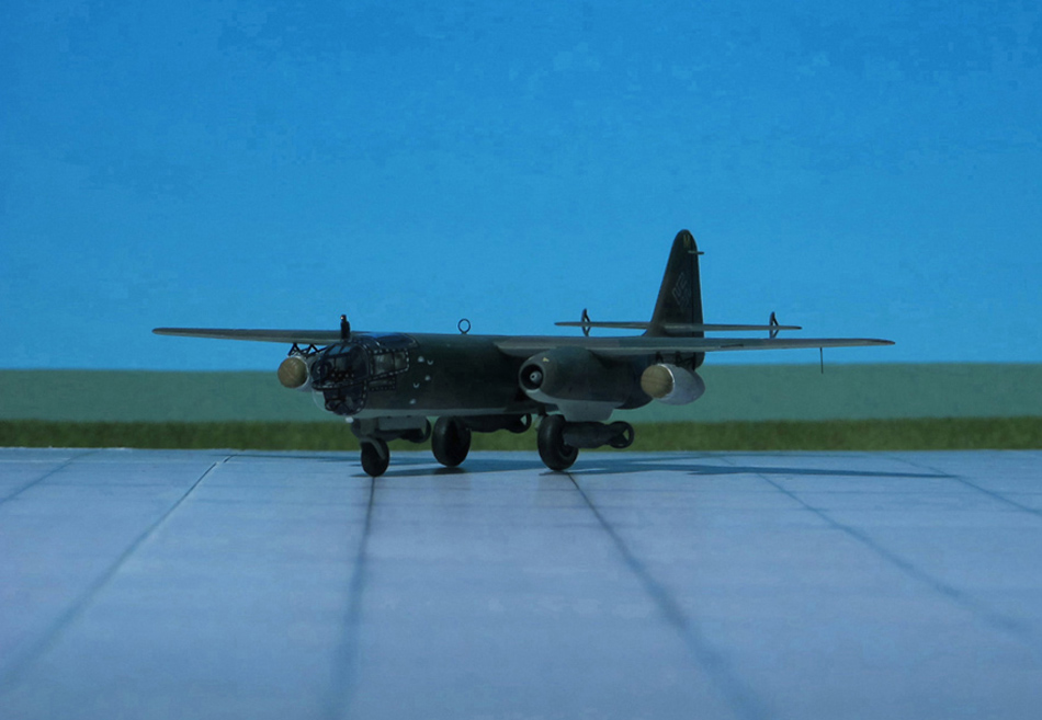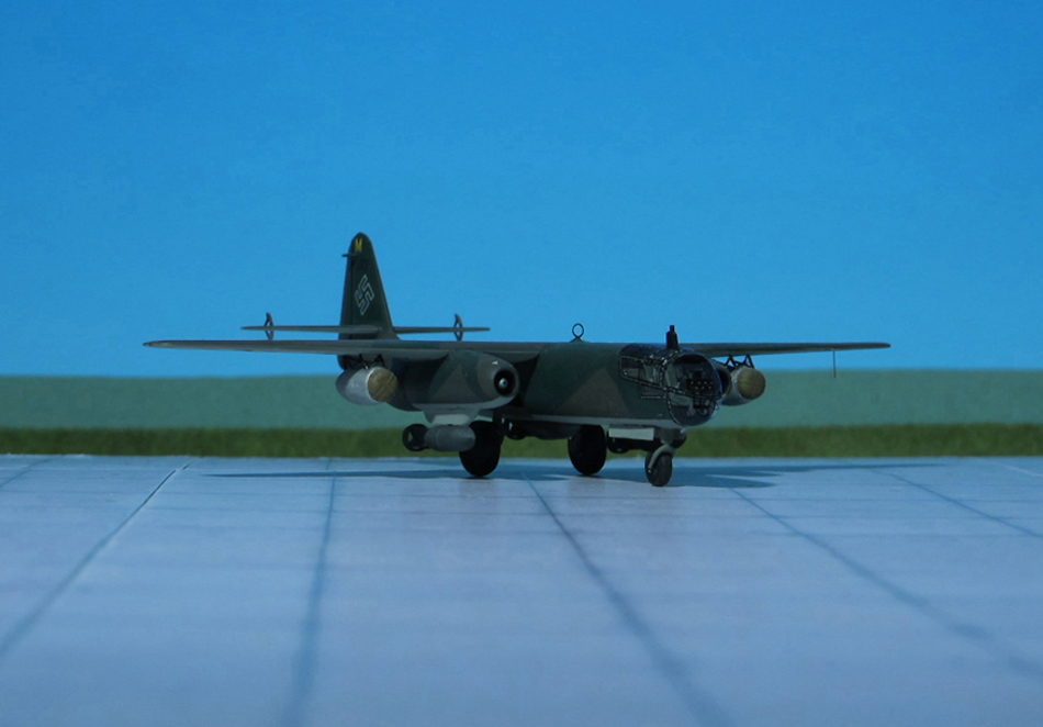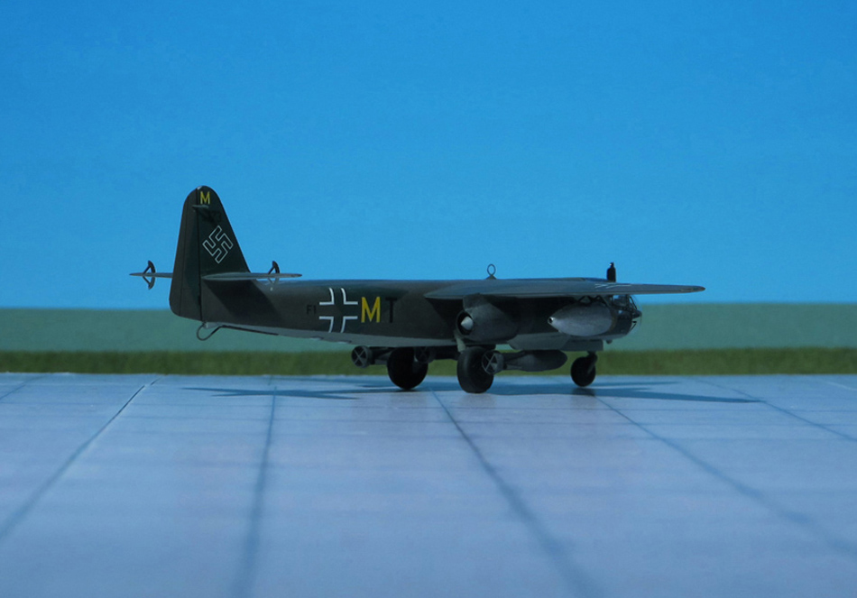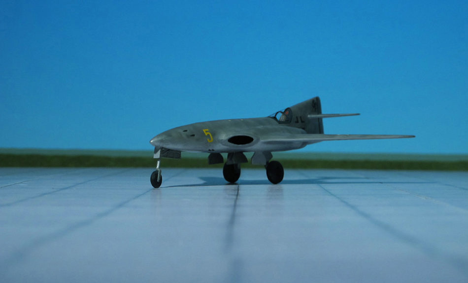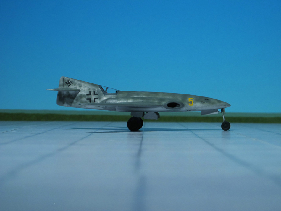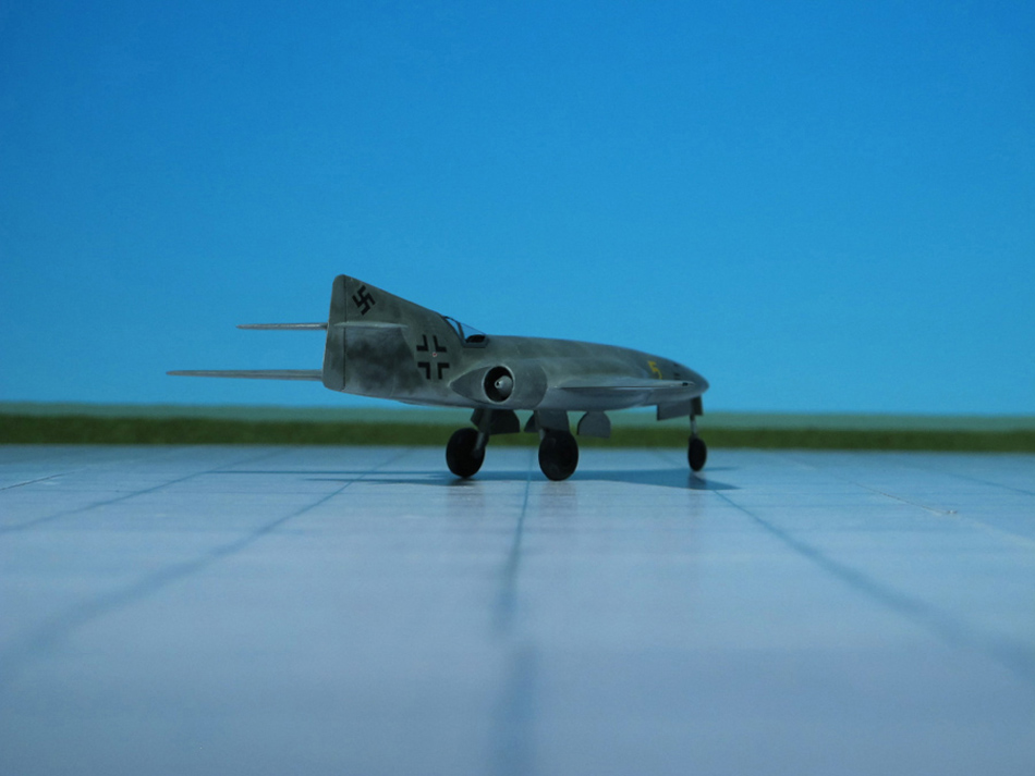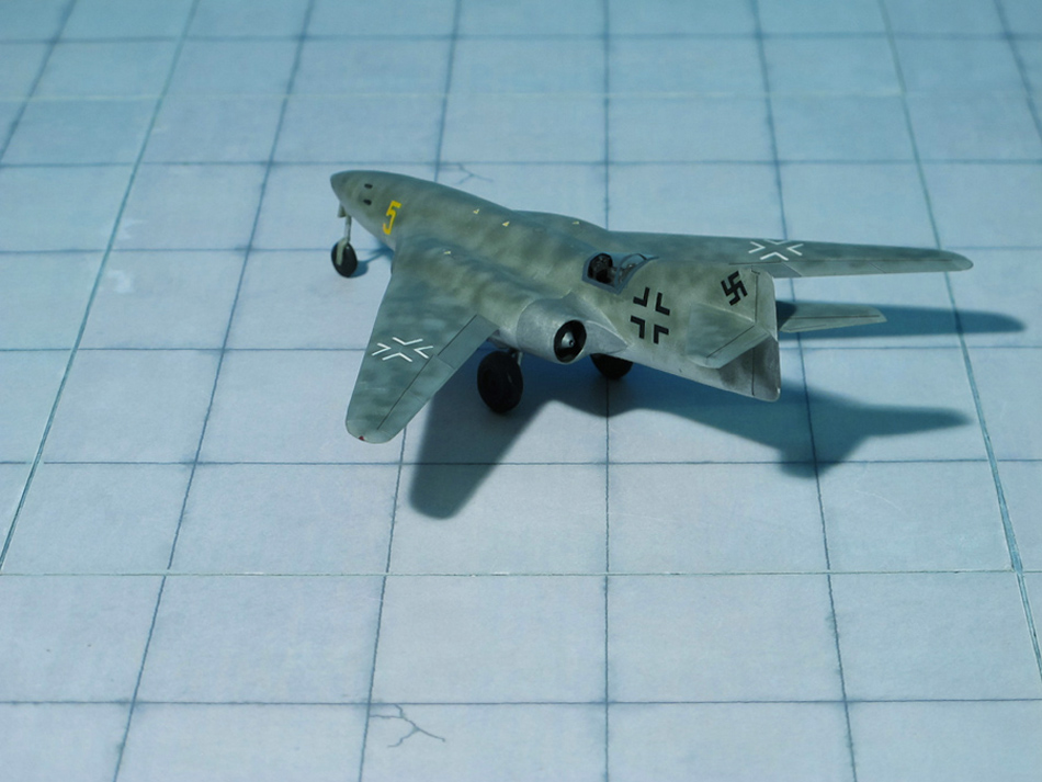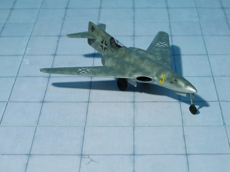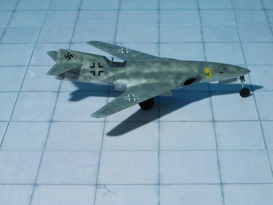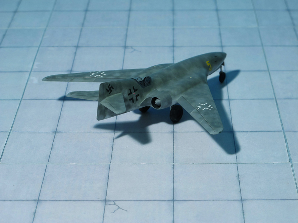
TYPE: Rocket powered high-altitude reconnaissance aircraft
ACCOMMODATION: Pilot only in prone position in pressurized cockpit
POWER PLANT: One Walter HWK 109-509 bi-fuel liquid rocket engine, rated at 1,650 kp at 40,000 ft
PERFORMANCE: 435 mph at 75,459 ft
COMMENT: Beginning in 1940, the DFS (Deutsches Forschungsinstitut für Segelflug, German Research Institute for Sailplanes) started an ambitious program to achieve supersonic flight. Since the only engines powerful enough and available at the time were rocket engines, it was realized that the solution was to have the assault on the sound barrier take place at a high altitude. It was decided to divide the program into three sections:
The first part was concerned with developing and testing of the pressurized cockpit section, the method of pilot escape in case of emergency and performance testing of rocket engines at high altitudes.
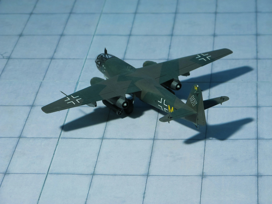
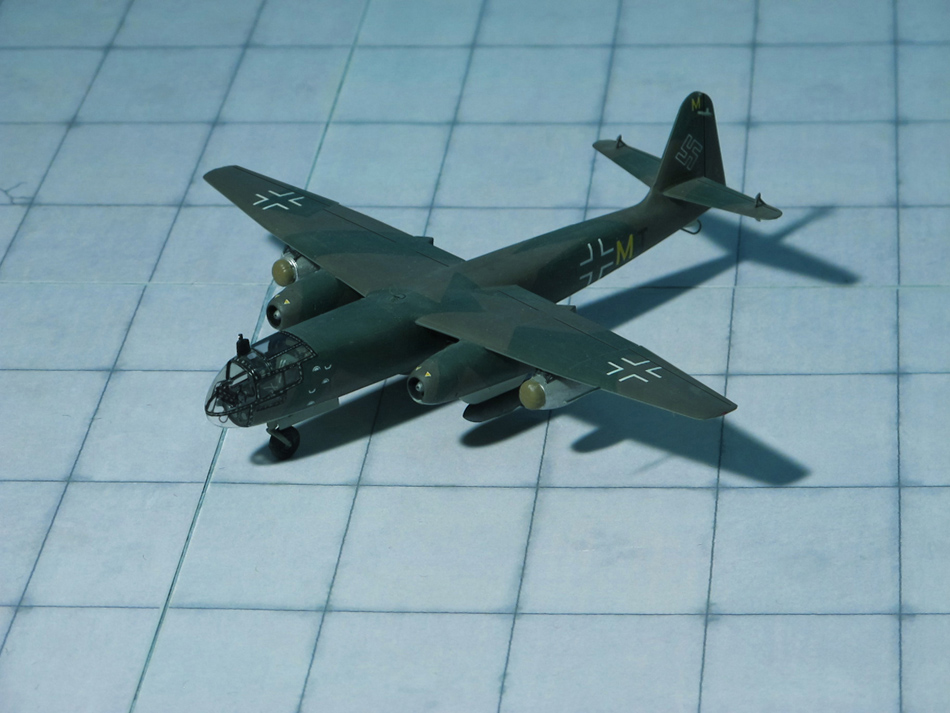
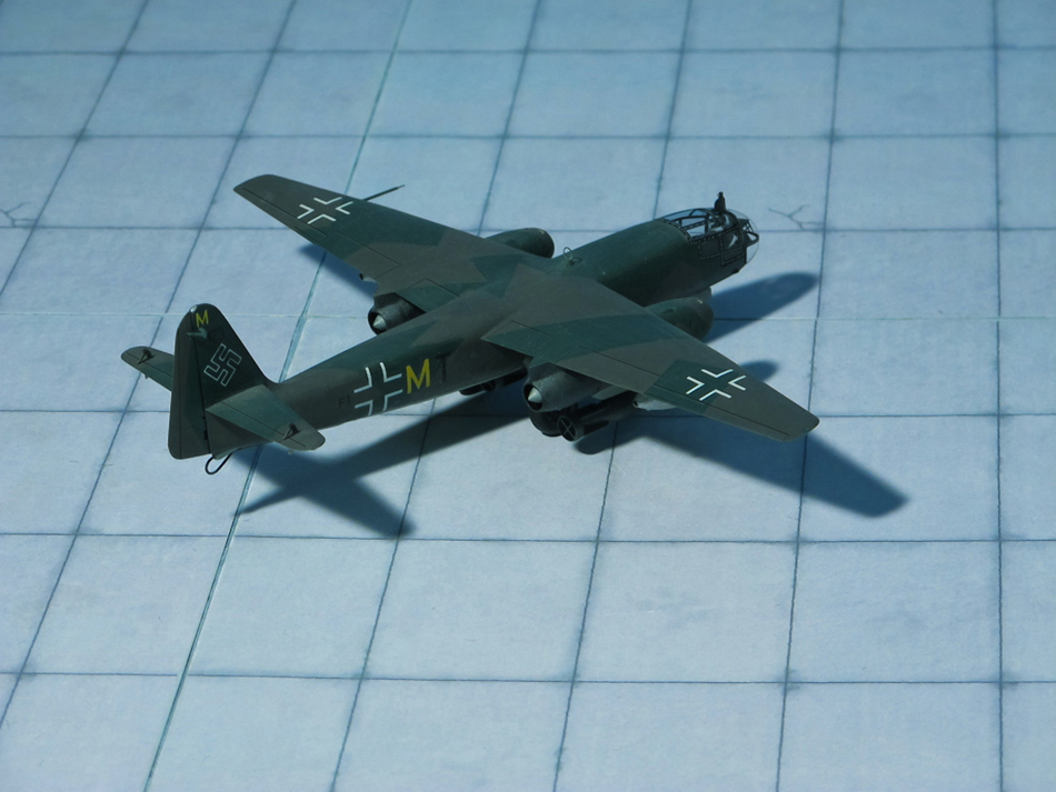
The second part was to discover the performance of various sweptback wing configurations. The DFS acquired the Heinkel P.1068 designs for a four-engined turbojet bomber with various wing sweep angles.
The third and last part was to actually build a supersonic aircraft with information learned in the above two steps, which was eventually to become the DFS 346.
The DFS decided to design a new aircraft (although much was learned in an earlier design, the DFS 54) to investigate the first part of their three-step program. Thus, in 1941, the RLM assigned the number 228 to the aircraft, and requested that the DFS 228 also be designed for high-altitude reconnaissance duties as well as research work.
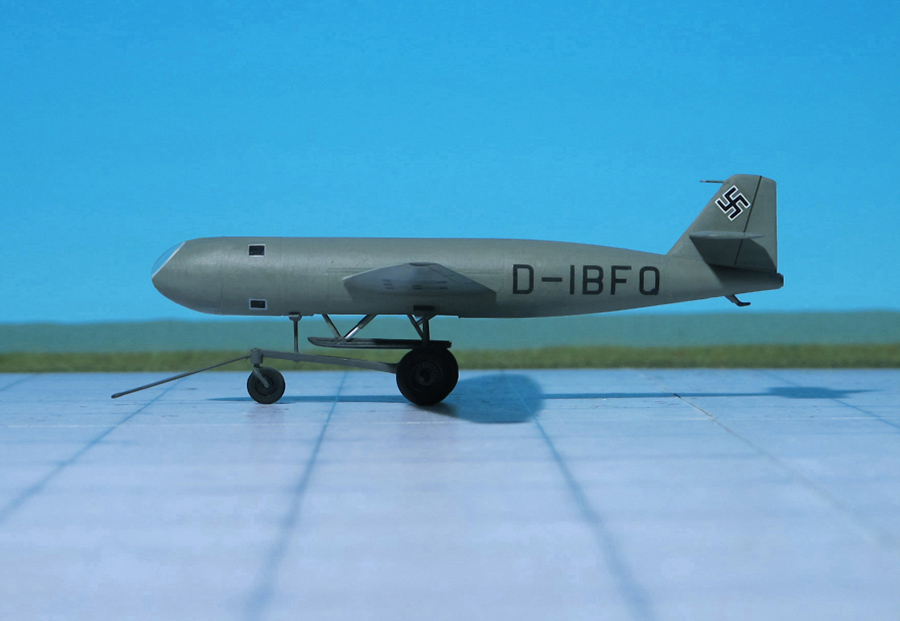
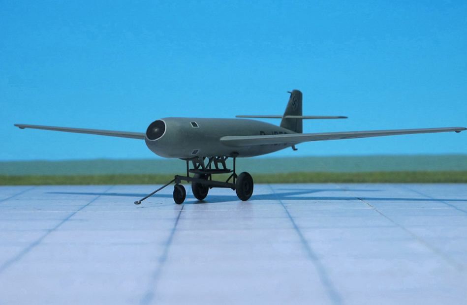
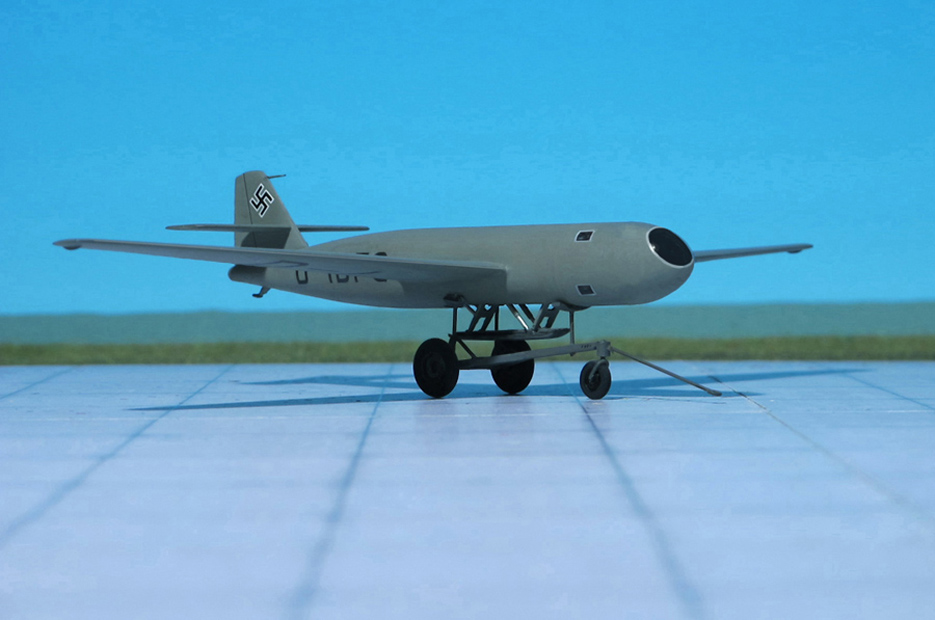
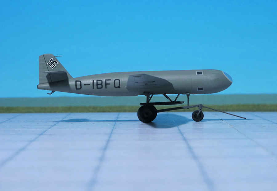
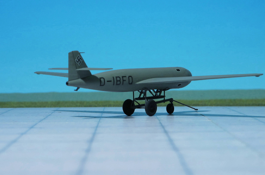
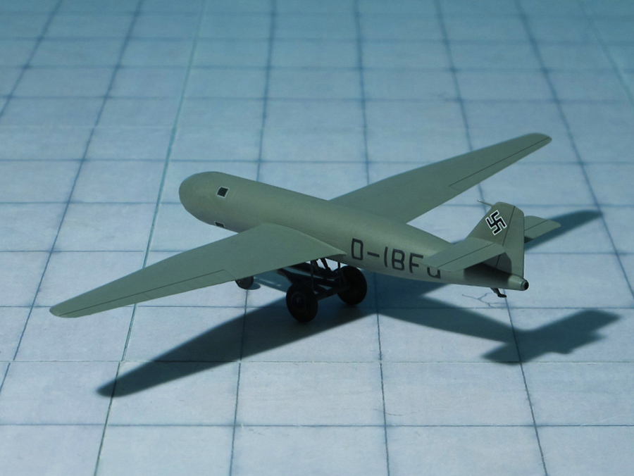
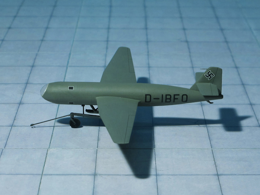
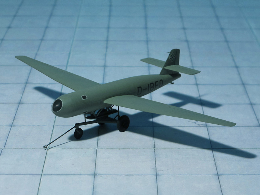
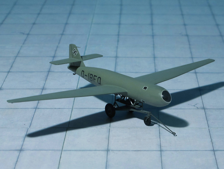
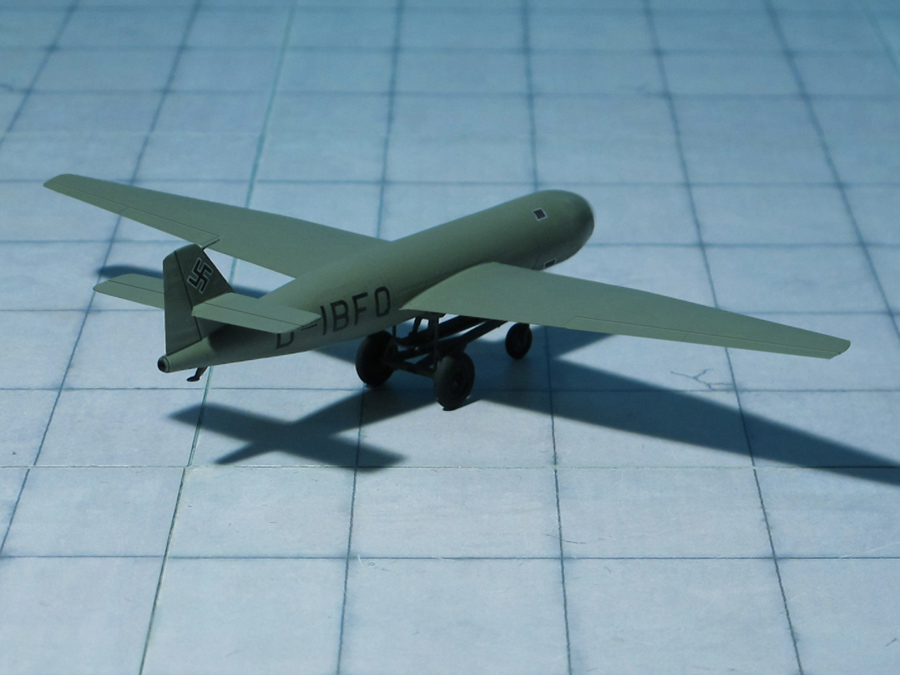
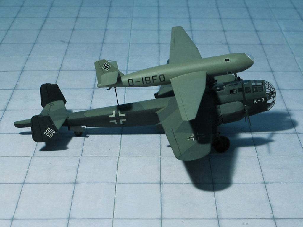
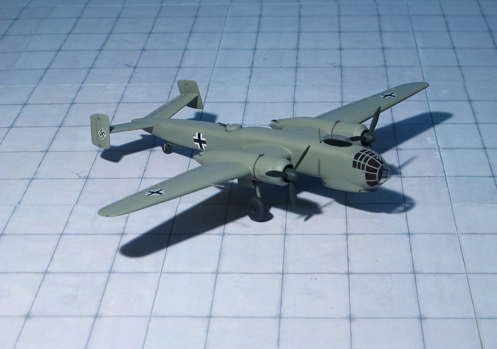
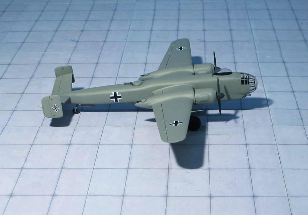
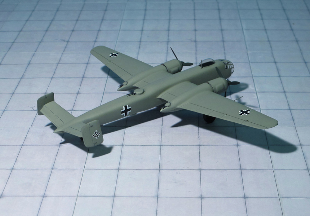
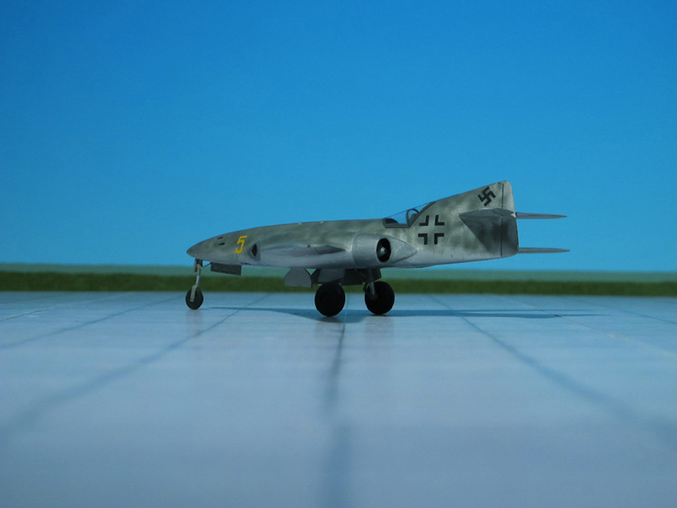
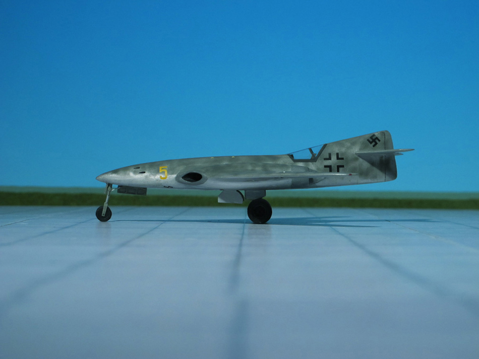
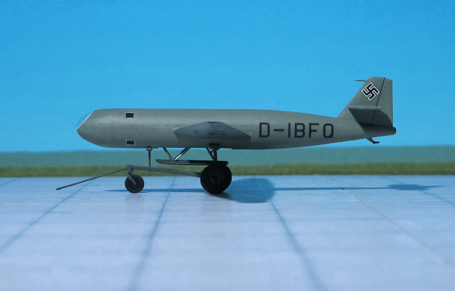
The first prototype of the DFS 228 (coded D-IBFQ) was completed in 1943 by the DFS, although the control sections and landing skid were built by Schmetz Company. The fuselage of the DFS 228 V1 consisted of three circular sections: the nose section containing the cockpit; a center section which contained the landing skid, fuel tanks and a Zeiss infra-red camera; and the tail section with the Walter HWK 509A-1 or A-2 rocket engine. The wing was attached at the mid-fuselage point, and featured 4.5 degrees of dihedral. Wooden construction was used for the entire wing, with a single laminated wooden spar running from wingtip to wingtip, wooden ribs and a plywood covering. Wide-span divided ailerons were fitted to the wing (the inner section acted as landing flaps), and lift spoilers were also fitted to the upper and lower wings. A conventional tail unit was used, also with all wooden construction. Landing was done on a retractable skid. Since the DFS 228 was to operate in extremely high altitudes, a completely pressurized cockpit was designed. Although it was thought at first that the pressure cabin could be of wooden construction, a metal compartment was built after the wooden one failed to hold sufficient pressure. The nose section was double-walled constructed with aluminum foil insulation. The V1 prototype had a conventional seated pilot’s position, but the V2 and later aircraft were to have a prone pilot position, due to the difficulty of of sealing such a large compartment with the pilot seated upright. All glazed areas were made of double layered Plexiglas and were provided with warm air circulation between layers to prevent frosting of the Plexiglas.
After pressure sealing problems became apparent on the V1 cockpit, it was decided to go with a prone pilot. An adjustable horizontal couch was provided for the pilot to lay on; all controls, oxygen supplies and cockpit equipment mounted directly to the steel tube structure which was then attached directly to the main fuselage bulkhead at the back of the cockpit. This also had the added advantage of keeping the pressurized area small. Thus it was easier to keep sealed. The new cockpit arrangement was incorporated in to the DFS 228 V2 and later aircraft.
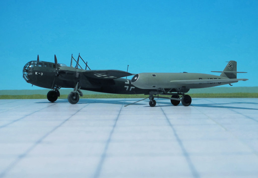
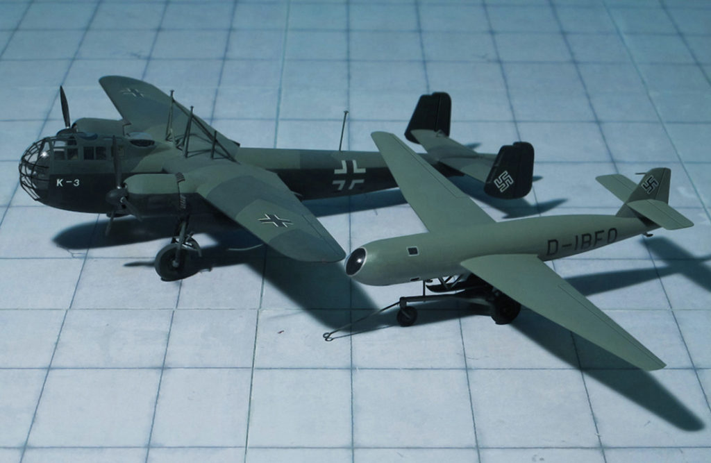
A very interesting flight plan was arranged for the operational recognizance DFS 228. It was to be mounted above (or could be towed behind) a carrier aircraft (usually a Do 217K), where it was then carried to approximately 32.808 feet. Upon release, the DFS 228 would then ignite its rocket engine until an altitude of about 75.460-82.021 feet was reached. By this time, the DFS 228 would be over its photographic target area and after its reconnaissance mission was fulfilled, the aircraft would then make a long glide back to base.
In the case of an emergency at high altitudes, the complete pressurized nose section (with all life support equipment attached) could be jettisoned by firing four explosive bolts, or it could take place automatically when the cockpit pressure dropped below a minimum level. An automatic parachute would then deploy to stabilize and slow the descent. When a safe altitude was reached, the pilot was ejected by compressed air, and would then descend to the ground using his personal parachute. This escape procedure was successfully tested by the Soviets after the war, with a captured DFS 346, which had a similar escape system.
DFS 228 V1 flight trials were made at Hörsching, southwest of Linz, by the DFS and also by Erprobungsstelle Rechlin in late 1944. Over 40 test flights were made, and although powered flight was to take place in February 1945, none were actually made using rocket power, and none exceeded 32.808 feet. It was in these tests that the upright pilot’s position was found to be unsuitable for proper cockpit pressurization. The decision was made to go with the prone position cockpit, and was included into the DFS 228 V2, which was built and also flight tested.
The main faults found with the 228 were that it suffered from poor aileron effectiveness at high altitudes and that the elevators were very sensitive. Other than the early pressurization problems, the general handling was satisfactory and the problems would not hamper the intended role of the aircraft. A potential problem could have arisen with the use of the Walter HWK 509A1 or A-2 rocket engines, due to the fact that the flight profile meant for the rocket engine to be intermittently operated, and the possibility existed of valves and pumps freezing up at the extreme altitudes and low temperatures in which the flight was to take place. Of course, newer rocket engines were continually being developed, and perhaps some sort of heating system or the possibility of using M-Stoff and A-Stoff (methanol and oxygen) for fuels, which could have operated at much lower temperatures, could have been developed.
Although powered flight had not been attempted at the time of Germany’s collapse, the construction of a pre-production batch of 10 DFS 228A-0 aircraft had begun at Griesheim, near Darmstadt.
The DFS 228 V2 was destroyed at Hörsching in May 1945, only the forward section had parts worth salvaging. The DFS 228 V1 survived the war, and was surrendered at Ainring in the US Zone of Occupation. On June 18, 1945, it was taken by road to the US Air Technical Intelligence Unit at Stuttgart. It was later sent to the RAE Farnborough in June 1946, and although allegedly was sent to the scrap pile in 1947, another report has the DFS 229 V1 being sent to Slingsby Sailplanes Ltd. at Kirkbymoorside in Yorkshire. Strangely enough, Slingsby offered a design for their T44, a stratospheric research sailplane which incorporated several DFS 228 features, including the detachable pressurized cockpit section (Ref.: 17).