TYPE: Carrier-based reconnaissance aircraft, land-based night fighter
ACCOMMODATION: Crew of two
POWER PLANT: One Nakajima NK9B Homare 11 air-cooled radial engine, rated at 1,991 hp
PERFORMANCE: 380 mph at 20,000 ft
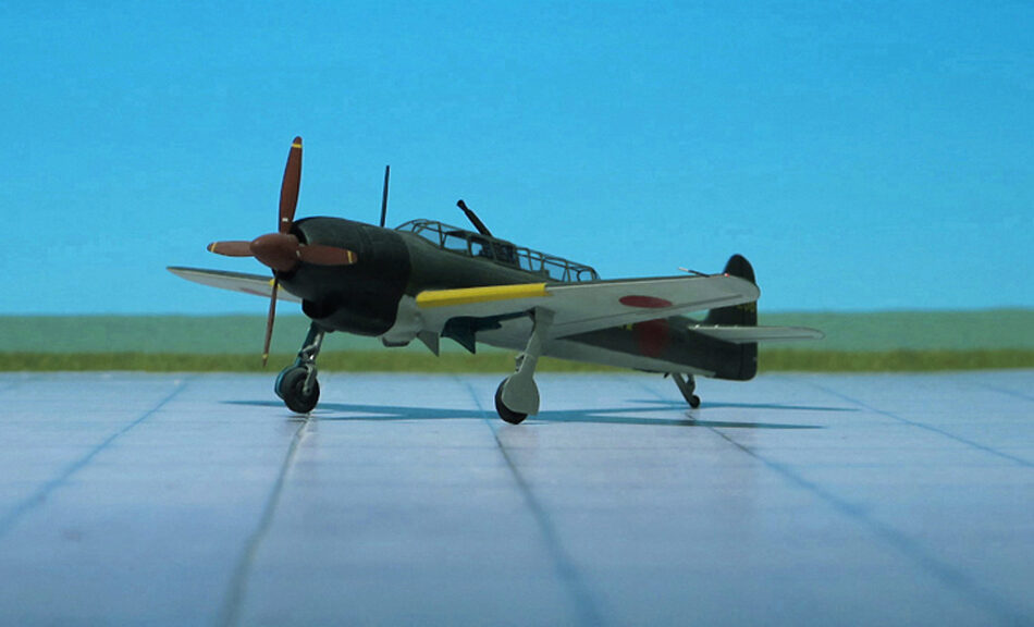
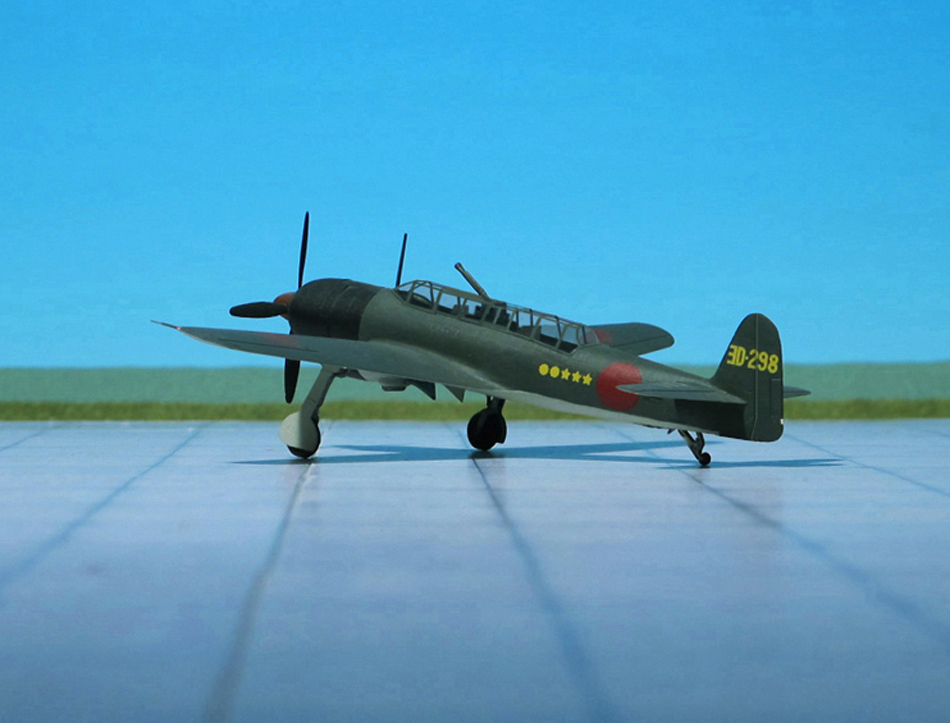
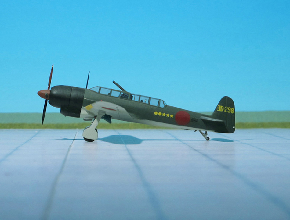
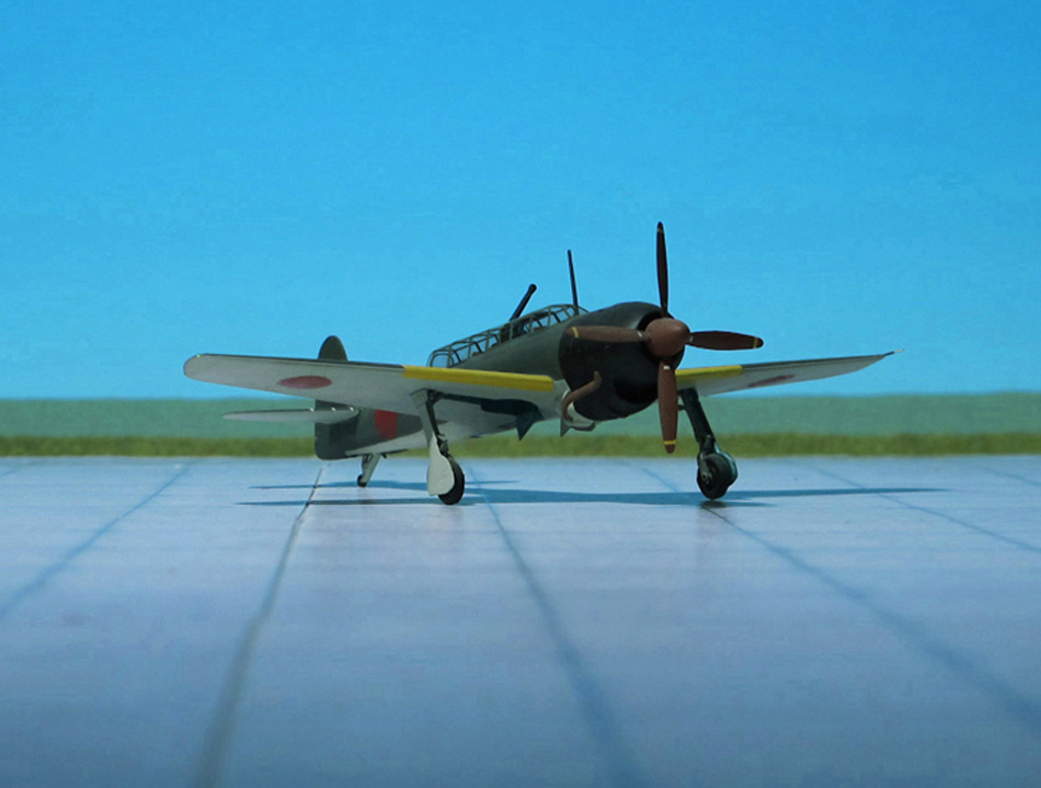
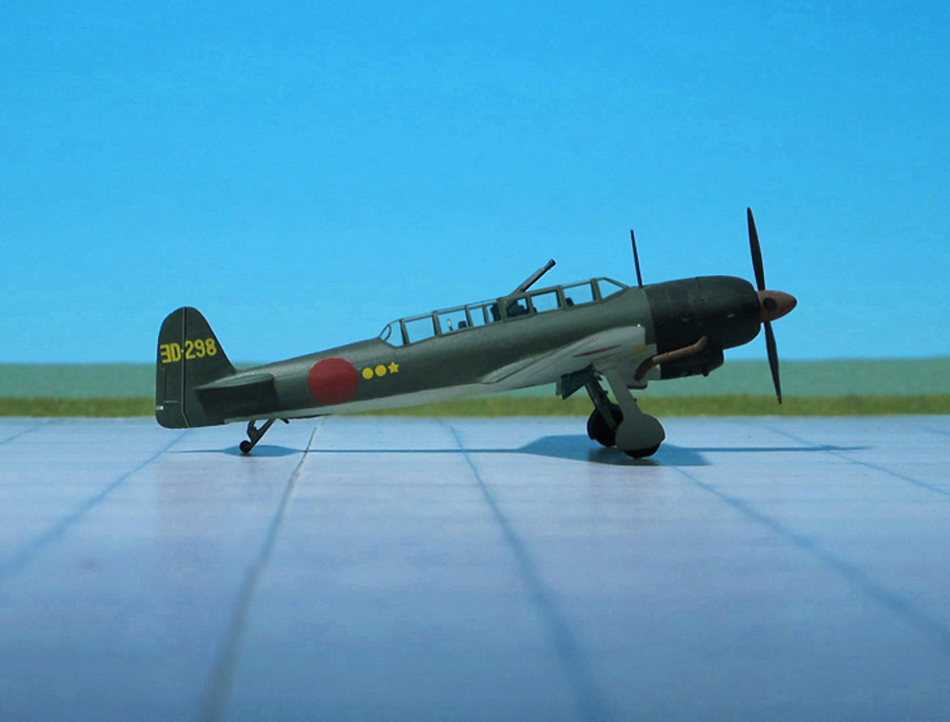
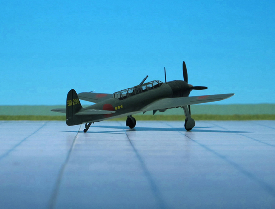
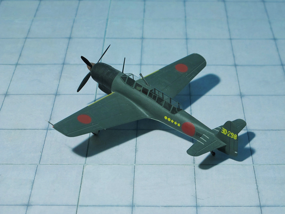
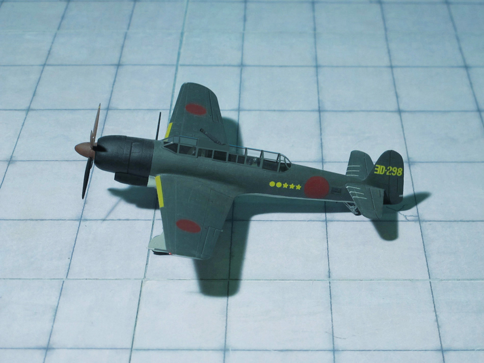
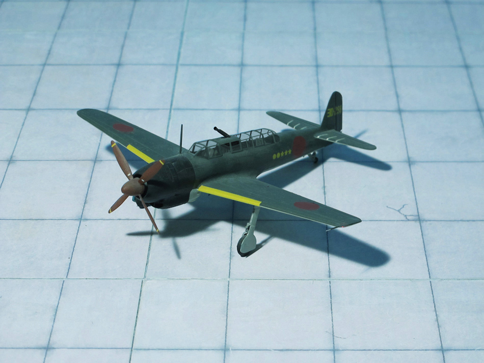
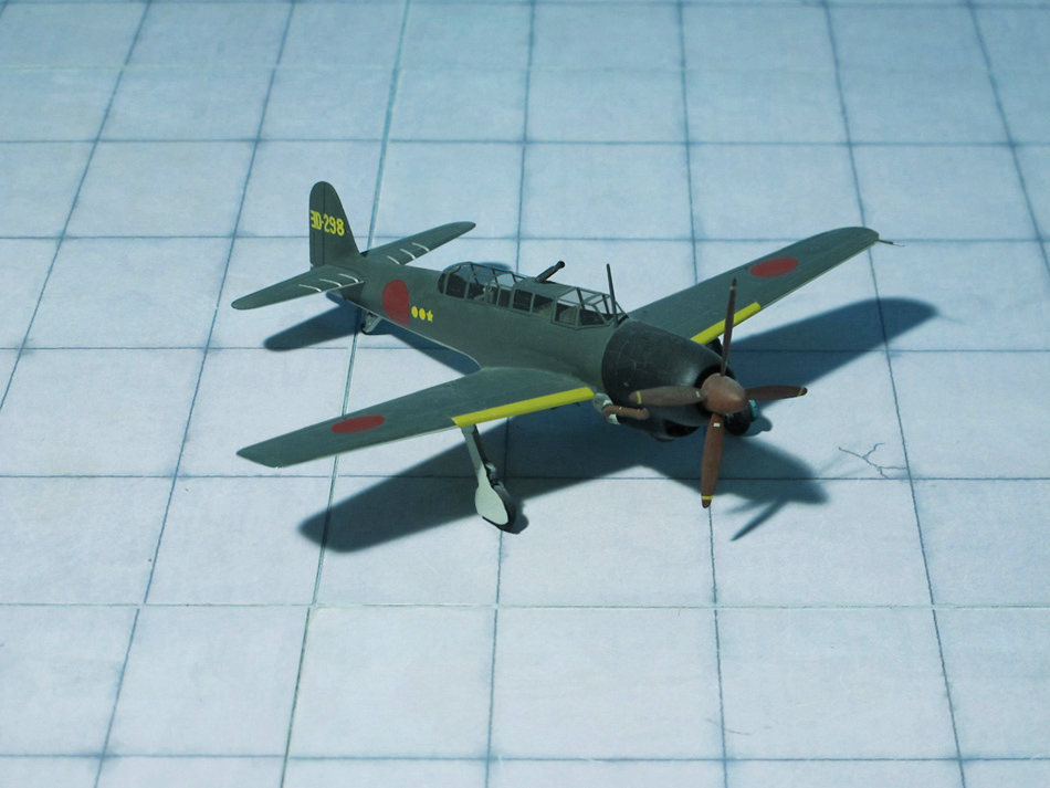
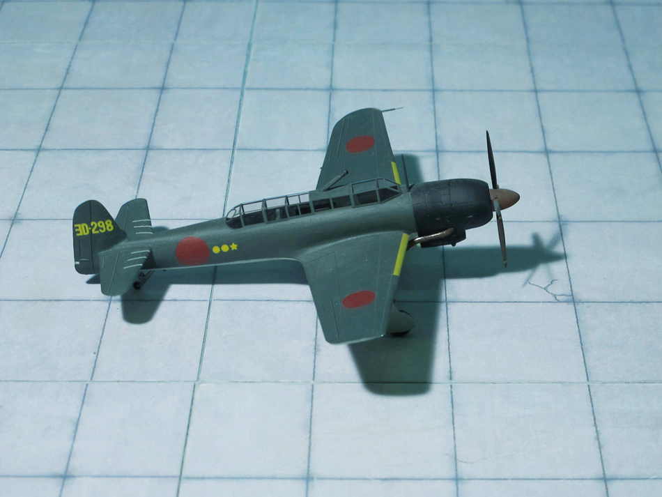
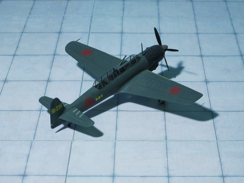
COMMENT: The Nakajima C6N Saiun ( “Iridecent Cloud“) was a carrier-based reconnaissance aircraft used by the Imperial Japanese Navy Air Service in World War II. Advanced for its time, it was the fastest carrier based aircraft put into service by Japan during the war. The Allied reporting name was Myrt.
The Nakajima C6N originated from a 1942 Imperial Japanese Navy specification for a carrier-based reconnaissance plane with a top speed of 403 mph at 19,700 ft and a range of 2,500 nautical miles. Nakajima’s initial proposal, designated N-50, was for a craft with two 1,000 hp engines housed in tandem in the fuselage, driving two propellers mounted on the wings. With the development of the 2,000 hp class Nakajima Homare engine, the dual powerplant configuration was abandoned and Nakajima decided on a more conventional single-engine layout. Unfortunately the new Homare’s power output was less than expected, and the design had to be optimized in other areas. The resulting aircraft was designed around a long and extremely narrow cylindrical fuselage just large enough in diameter to accommodate the engine. The crew of three sat in tandem under a single canopy, while equipment was similarly arranged in a line along the fuselage. The C6N’s low-mounted laminar flow wing housed fuel tanks and was fitted with both Fowler and slit flaps and leading-edge slats which lowered the aircraft’s landing speed to ease use aboard aircraft carriers. Like Nakajima’s earlier B6N Tenzan torpedo bomber, the vertical stabilizer was angled slightly forward to enable tighter packing on aircraft carrier decks.
The C6N’s first flight was on May 1943, with the prototype demonstrating a speed of 397 mph. Performance of the Homare engine was disappointing, especially its power at altitude, and a series of 18 further prototypes and pre-production aircraft were built before the Saiun was finally ordered into production in February 1944.
Although designed for carrier use, by the time it entered service in September 1944 there were few carriers left for it to operate from, so most C6Ns were flown from land bases. Its speed was exemplified by a telegraph sent after a successful mission: “No Grummans can catch us.” The top speed of the Grumman F6F Hellcats was indeed of the same level, so overtaking a Saiun was out of the question.
A total of 463 aircraft were produced. A single prototype of turbocharged development mounting a 4-blade propeller was built; this was called the C6N2 Saiun-kai. Several examples of a night fighter version C6N1-S with oblique-firing (Schräge Musik configuration) single 30 mm (or dual 20 mm) cannon were converted from existing C6N1s. As Allied bombers came within reach of the Japanese home islands, a first class night fighter was required. This led Nakajima to develop the C6N1-S by removing the observer and replacing him with two 20 mm cannons. The C6N1-S’s effectiveness was hampered by the lack of air-to-air radar, although it was fast enough to enjoy almost complete immunity from interception by Allied fighters. The 30 mm version was only used to attack Boeing B-29 Superfortress once, on August 1, 1945. The destructive power of the Type 2 cannon extended to twisting the skin of the Saiun’s lightweight fuselage.
A torpedo carrying C6N1-B was also proposed, but was not needed after most of Japan’s aircraft carriers were destroyed.
Despite its speed and performance, on 15 August 1945 a C6N1 happened to be the last aircraft to be shot down in World War II. Just five minutes later, the war was over and all Japanese aircraft were grounded (Ref. 24).
POWER PLANT: One BMW P.8011 radial engine with two turbochargers, rated at 2.900 hp
PERFORMANCE: 451 mph in 26.215 ft
COMMENT: By the beginning of 1942, the Focke-Wulf Fw 190A was established in production and service, and most of the more serious shortcomings that has revealed themselves during the fighter’s gestation had been ironed out. A solution had still to be found out. However, the performance of the aircraft at high altitudes was inadequate. So one of the preproduction airframe was fitted with a nitrous oxide injection or GM 1 system for use above the rated altitude of the engine. The nitrous oxide, which was retained under pressure in liquid form in a tank aft of the cockpit, provided additional oxygen for the engine, but sometimes also acting as an antidetonant.
Flight testing proved disappointing. Effective combat altitude was boosted to some 26.000 ft, but insufficient nitrous oxide could be carried to increase power for more than brief periods, difficulties were experienced in lagging the pipelines, and the weight of the system, with its compressed air cylinders and heavily-lagged GM 1 tank, was almost as much as the total gun armament of the standard fighter.
Focke-Wulf was convinced that the desired performance could not be achieved with the BMW 801, and that the engine should be replaced by a liquid-cooled power plant. The design team with Prof. K. Tank favored the Daimler-Benz DB 603, but this engine was viewed with disfavor by the RLM, having been developed by Daimler-Benz without official sanction. Tank was informed that the improved performance now being sought should be achieved with developments of the BMW 801 air-cooled radial.
Meanwhile BMW was working on the BMW 802, a large air-cooled radial engine consistig of two rows of nine cylinders. It was essentially an 18-cylinder version of the 14-cylinder BMW 801. The BMW 802 emerged with an almost identical displacement to the American 18-cylinder Wright R-3350 Duplex Cyclone and somewhat larger than the British Bristol Centaurus. Although promising at first, development dragged on and the project was eventually cancelled.
Another idea to improve the performance was to bolt two BMW 801s back to back. Although seemingly a simple concept, the resulting, 83.5 litre displacement BMW 803 was in fact fantastically complicated. The power of the engine could only practically be used in extremely large propellers, or, as selected, a contra-rotating pair of propellers. This required a large gearbox on the front of the engine, which combined with the layout of the cylinders, left no room for airflow over the cylinders. This demanded the addition of liquid cooling.
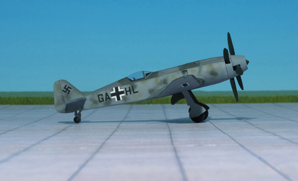
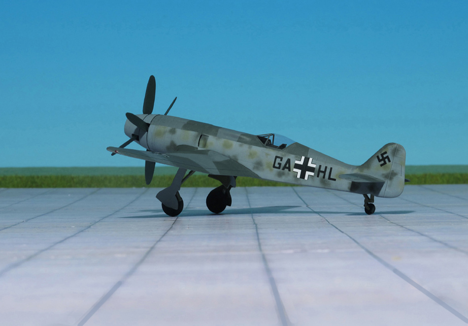
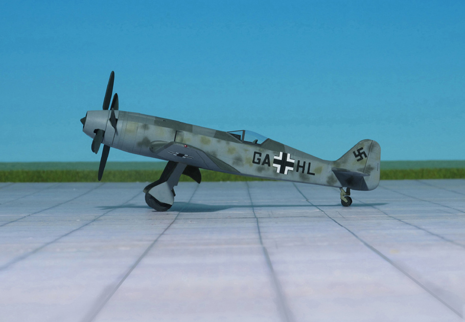
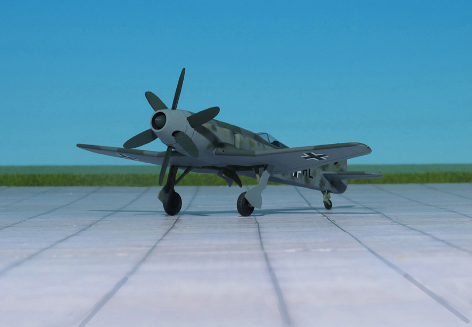
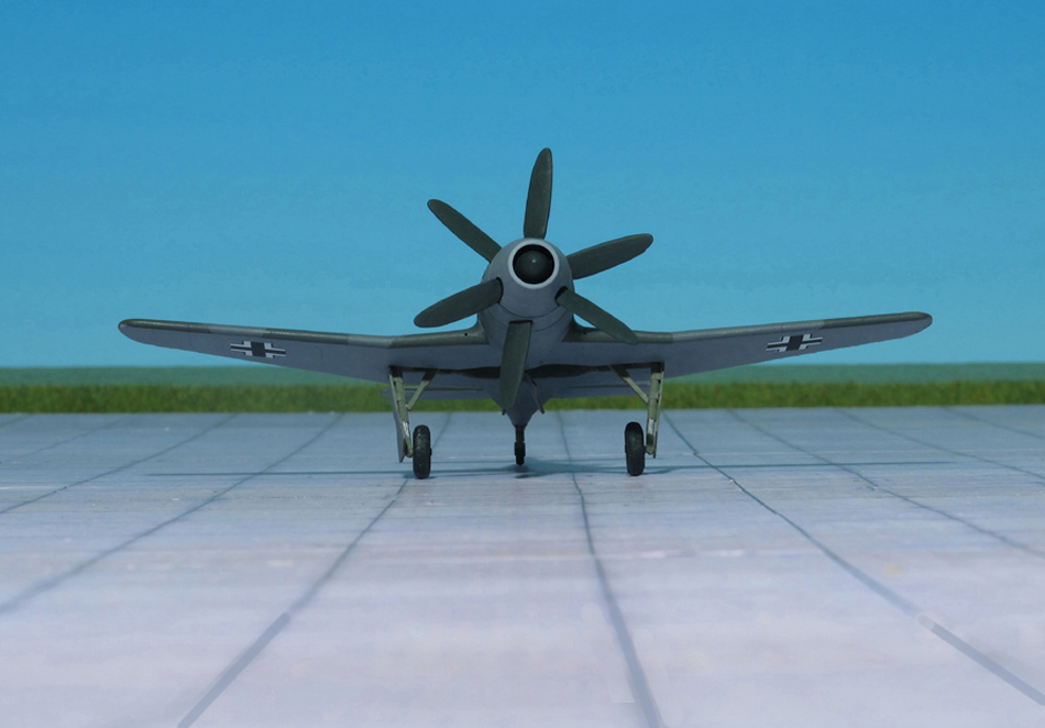
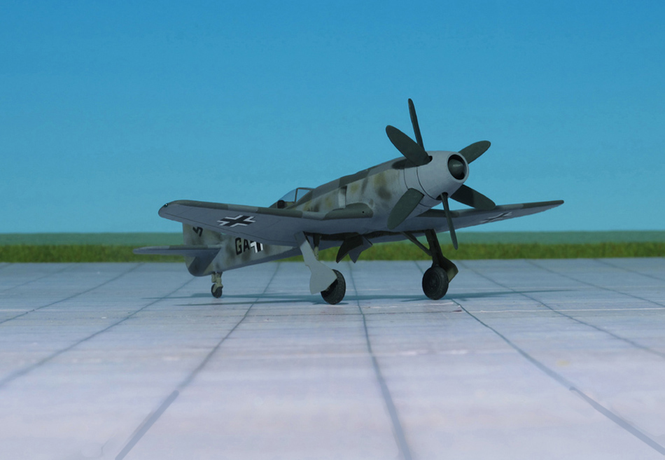
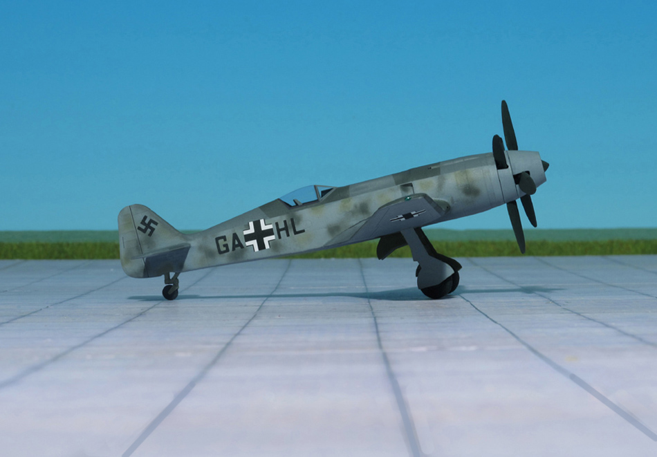
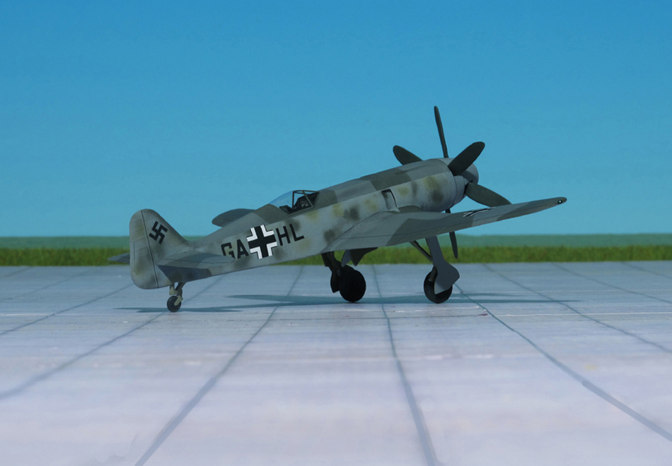
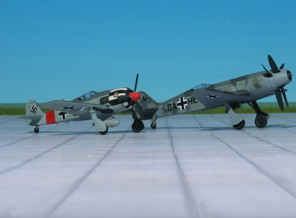
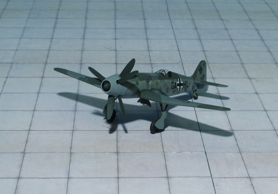
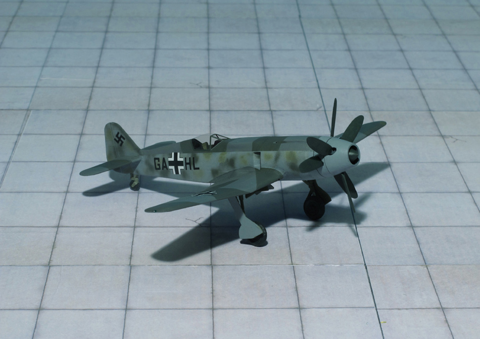
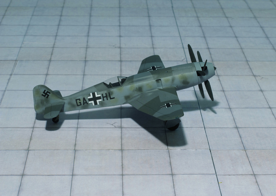
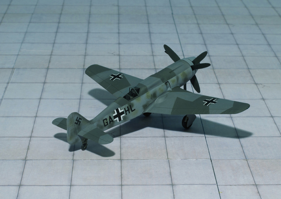
Based on this concept of a twin-engine a further improvement led to the BMW P.8011. This engine was, able to produce 2.900 hp at take-off. The supercharger was replaced by two gas turbines enclosed in an aerodynamic engine cowling and driving two contra-rotating three-bladed propellers.
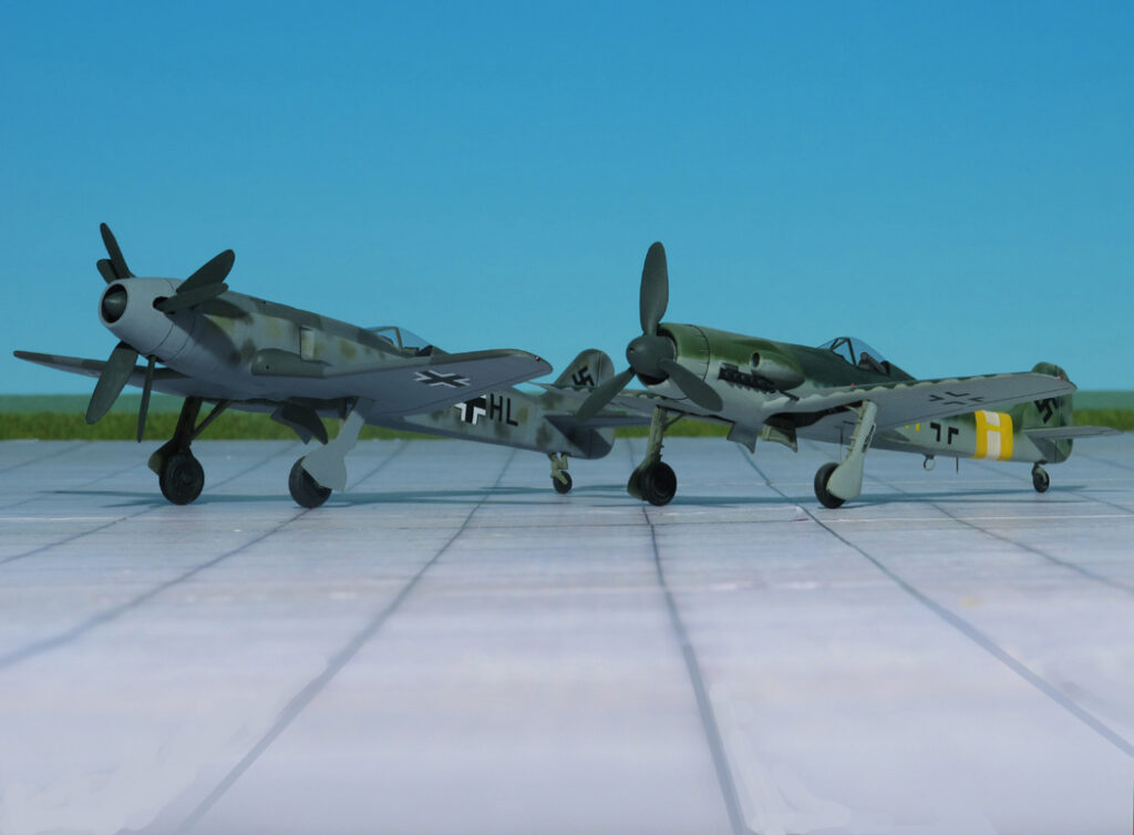
These engines were too heavy and powerful for the standard Focke-Wulf Fw 190 airframe. It was necessary to design a heavier airplane. The answer was a 125% scaled-up version of the Fw 190 with a wing of 42,7 ft span ad 371 sqft surface. The BMW P. 8011 was 38.7 ft long and the maximum weight was more than 11.900 lbs.
This new fighter was provided with an armored pressure cabin and used as high-altitude interceptor. Due to the war situation the project was cancelled in late 1944.
This monster fighter lacked any official designation and was only known as “Focke-Wulf Einsitzer mit BMW P.8011” (Focke-Wulf Single-seater with BMW P. 8011). By the end of 1944 in an article by General “Hap” Arnold, USAAF, published on 29 May 1944 in “Aviation News” refers it as Focke-Wulf Fw 290. But that is an error because the RLM Number “290” was given to the Junkers Ju 290 four-engine maritime control and transport aircraft (Ref.: 7, 24).
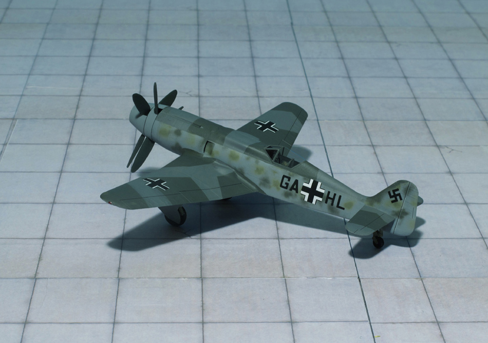
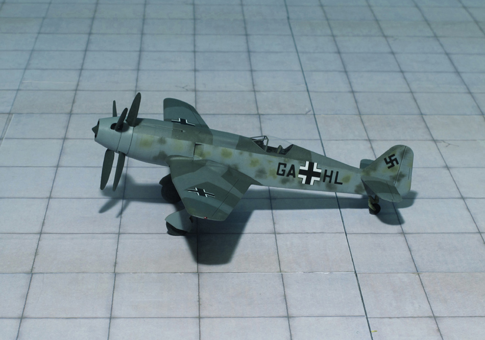
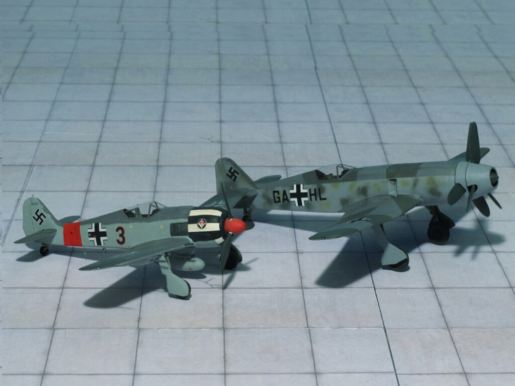
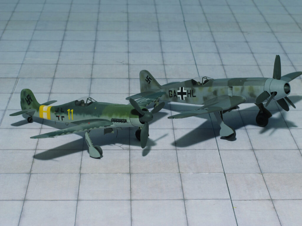
Focke-Wulf Single-Seat Fighter with BMW P.8011
Focke-Wulf Single-Seat Fighter with BMW P.8011
Focke-Wulf Single-Seat Fighter with BMW P.8011
Focke-Wulf Single-Seat Fighter with BMW P.8011
Focke-Wulf Single-Seat Fighter with BMW P.8011
Focke-Wulf Single-Seat Fighter with BMW P.8011
Focke-Wulf Single-Seat Fighter with BMW P.8011
Focke-Wulf Single-Seat Fighter with BMW P.8011 and Focke-Wulf Fw 190A-7/R2
Focke-Wulf Single-Seat Fighter with BMW P.8011 and Focke-Wulf Ta 152C-1
Focke-Wulf Single-Seat Fighter with BMW P.8011
Focke-Wulf Single-Seat Fighter with BMW P.8011
Focke-Wulf Single-Seat Fighter with BMW P.8011
Focke-Wulf Single-Seat Fighter with BMW P.8011
Focke-Wulf Single-Seat Fighter with BMW P.8011
Focke-Wulf Single-Seat Fighter with BMW P.8011
Focke-Wulf Single-Seat Fighter with BMW P.8011and Focke-Wulf Fw 190A-7/R2
Focke-Wulf Single-Seat Fighter with BMW P.8011and Focke-Wulf Ta 152C-1
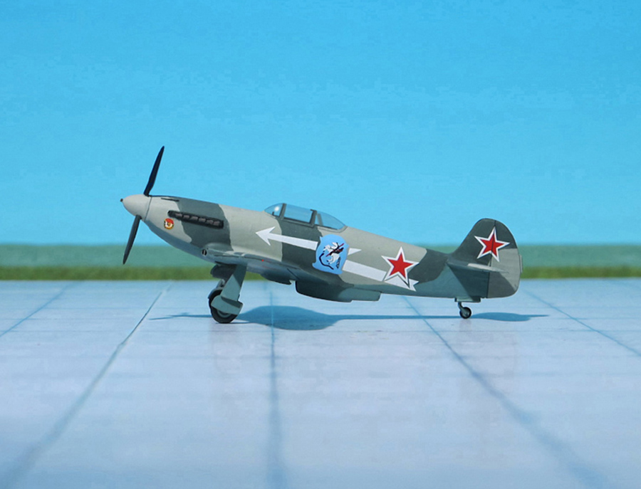
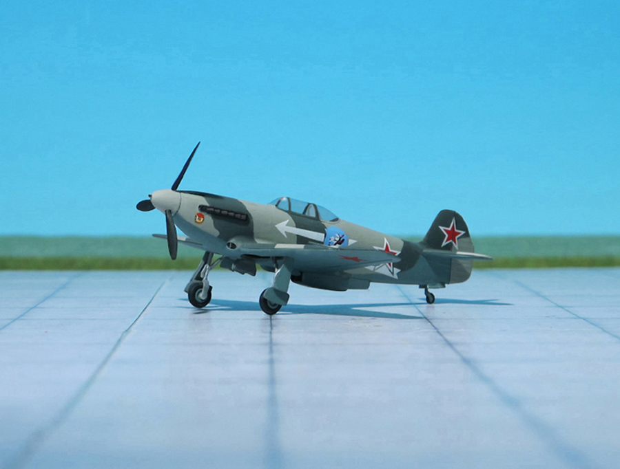
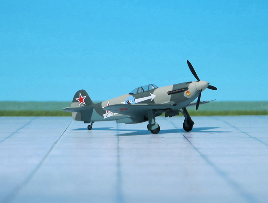
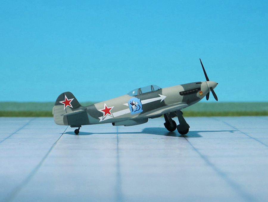
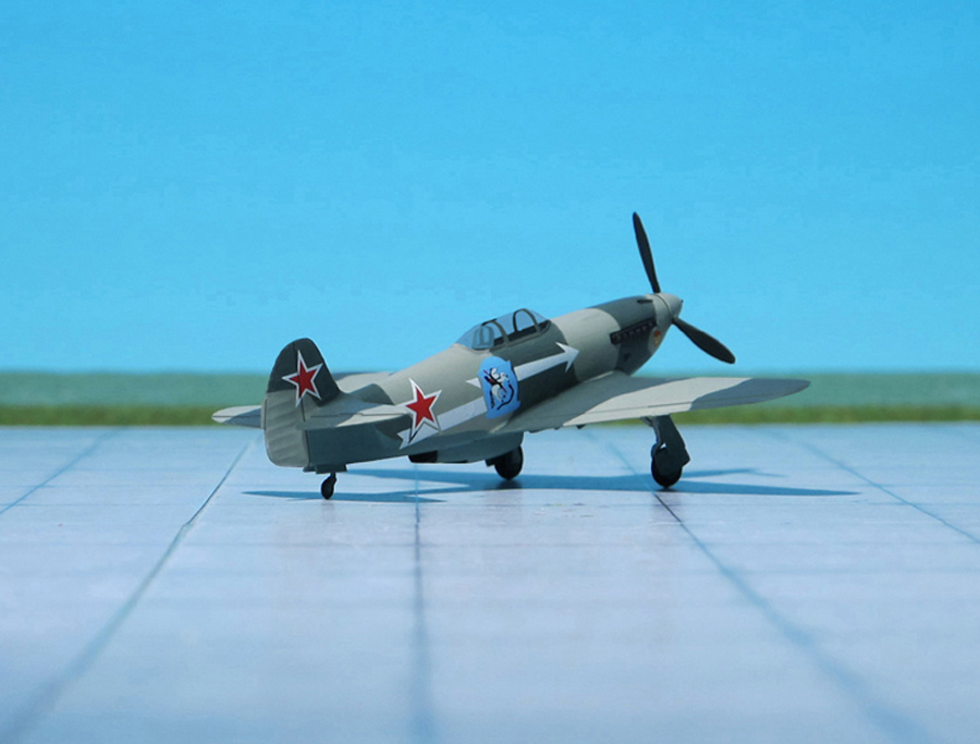
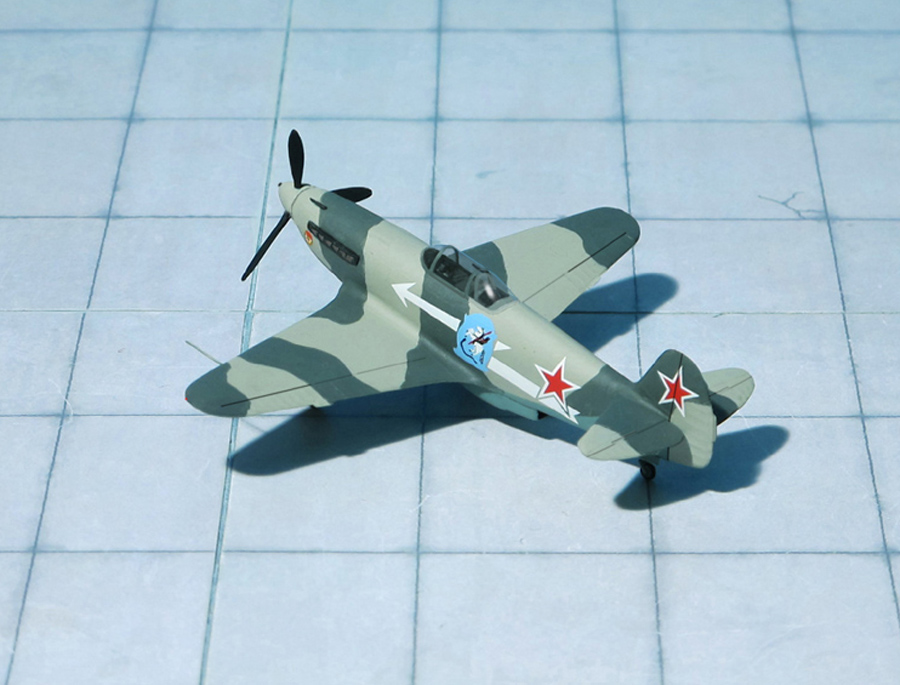
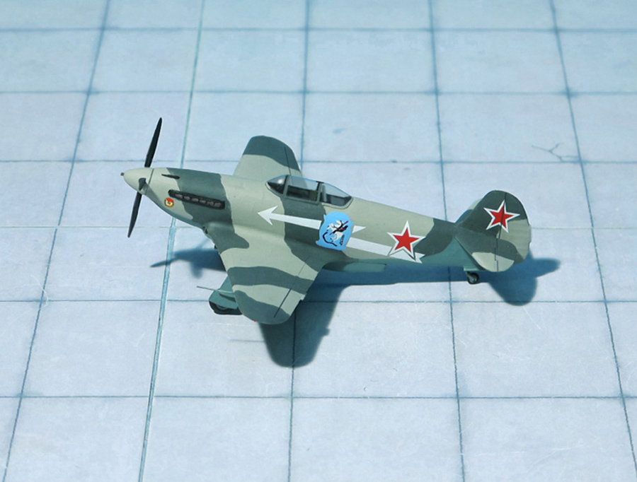
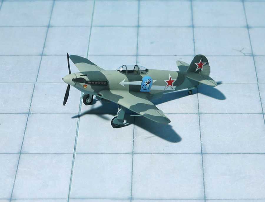
POWER PLANT: One Klimov VK-105PF2 liquid-cooled piston engine, rated at 1,290 hp
PERFORMANCE: 401 mph at 13,500 ft
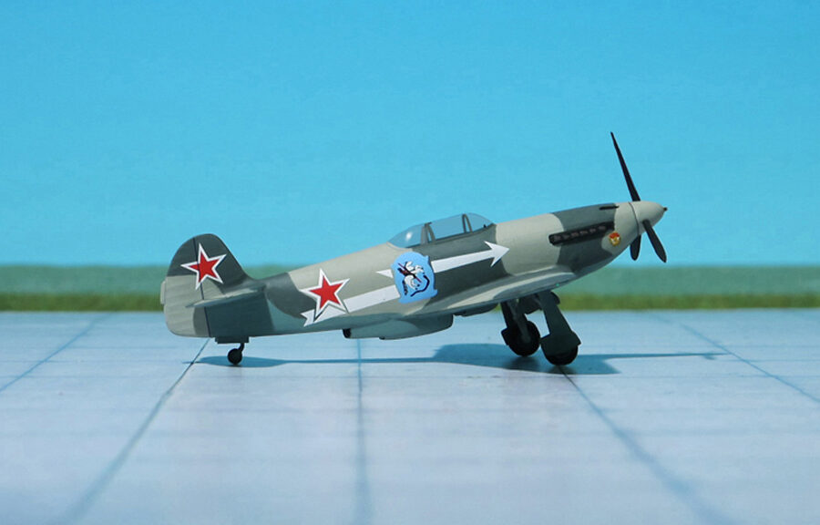
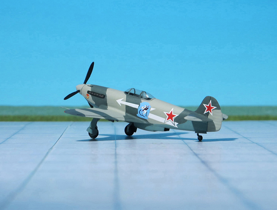
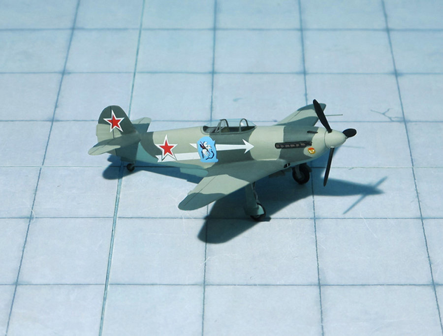
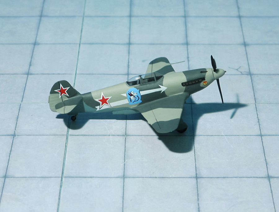
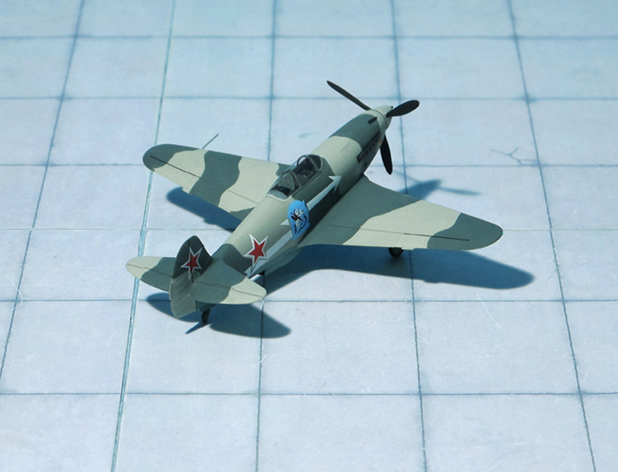
COMMENT: The Yakovlev Yak-3 was a single-engine single-seat World War II Soviet front line fighter aircraft. Robust and easy to maintain, it was much liked by pilots and ground crew alike. It was one of the smallest and lightest major combat fighters fielded by any combatant during the war. Its high power-to-weight ratio gave it excellent performance. It proved a formidable dogfighter.
In 1943, a group of designers headed by Alexander Sergeyevich Yakovlev designed the Yak-3, a further development of the proven Yak-1 aimed at improving survivability, flight characteristics and firepower, which required a lower weight, a higher-power engine and therefore, faster speed.
The first of two prototypes had a slatted wing to improve handling and short-field performance while the second prototype had a wooden wing without slats in order to simplify production and save aluminium. The second prototype crashed during flight tests and was written off. Although there were plans to put the Yak-3 into production, the scarcity of aviation aluminium and the pressure of the Nazi invasion led to work on the first Yak-3 being abandoned in late 1941.
In between 1942 and 1943, Yakovlev built the Yak-1M, a prototype that would ultimately lead to the Yak-3, coupled with the VK-105PF2, the latest iteration of the VK-105 engine family, where “P” indicated support for an autocannon that fires between the engine banks, through the hollow propeller shaft – mounting. It incorporated a wing of similar design but with smaller surface area (17.15 to 14.85 m2 , and had further aerodynamic refinements, like the new placement of the oil radiator, from the chin to the wing roots (one of the visual differences with the Yak-1, Yak-7, Yak-9). A second Yak-1M (originally meant as a “backup”) prototype was constructed later that year, differing from the first aircraft in that it had plywood instead of fabric covering of the rear fuselage, mastless radio antenna, reflector gunsight and improved armour and engine cooling.
The first 197 Yak-3 were lightly armed with a single 20 mm SHVAK cannon and one 12.7 mm UBS synchronized machine guin, with subsequent aircraft receiving a second UBS for a weight of fire of 2.72 kg (6.0 lb) per second using high-explosive ammunition. All armament was installed close to the axis of the aircraft with a cannon mounted in the engine “vee” firing through the propeller boss, synchronised machine guns in the fuselage, helping accuracy and leaving wings unloaded.
Lighter and smaller than Yak-9 but powered by the same engine, the Yak-3 was a forgiving, easy-to-handle aircraft loved by both novice and experienced pilots and ground crew as well. It was robust, easy to maintain, and a highly successful dog-fighter. It was used mostly as a tactical fighter, flying low over battlefields and engaging in dogfights below 13,000 ft.
Unresolved wartime problems with the Yak-3 included plywood surfaces coming unstuck when the aircraft pulled out of a high-speed dive. Other drawbacks of the aircraft were short range and poor engine reliability. The pneumatic system for actuating landing gear, flaps and brakes, typical for all Yakovlev fighters of the time, was troublesome. Though less reliable than hydraulic or electrical alternatives, the pneumatic system was preferred owing to the weight saving (Ref.: 24).
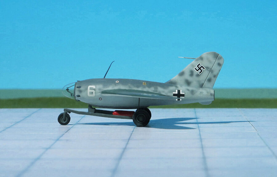
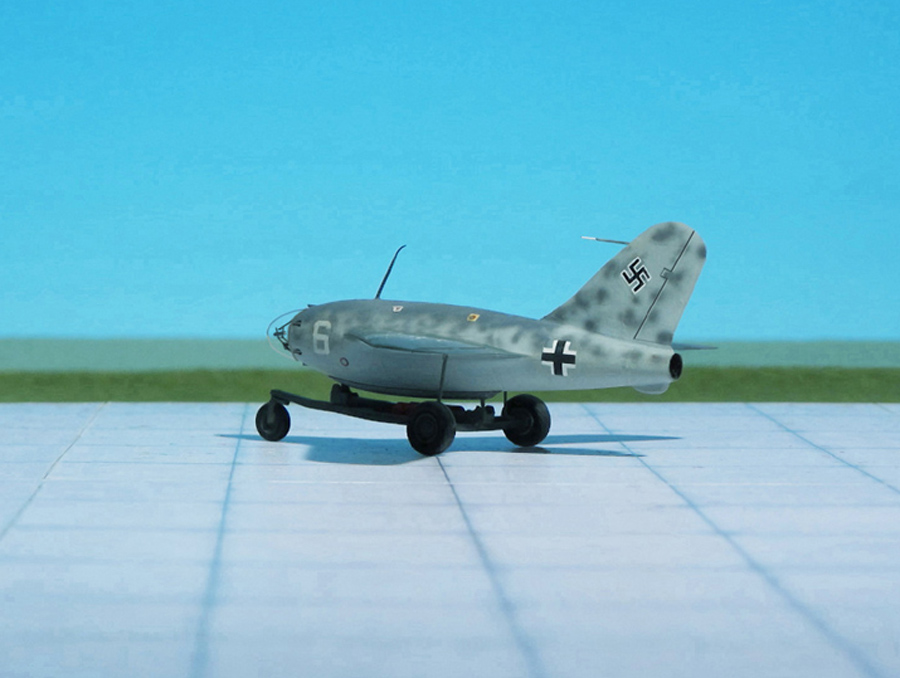
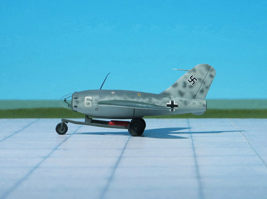
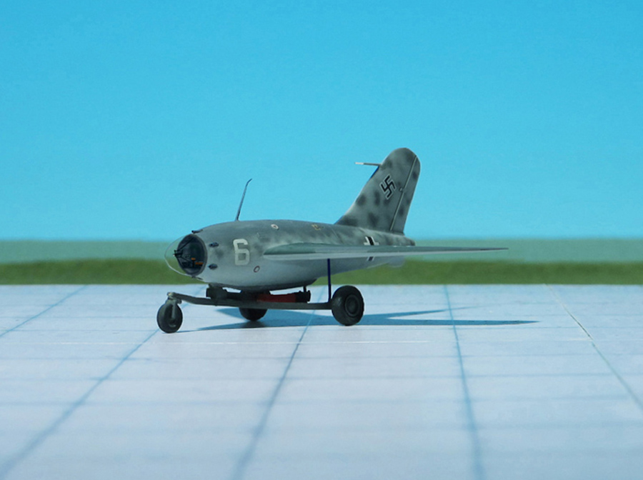
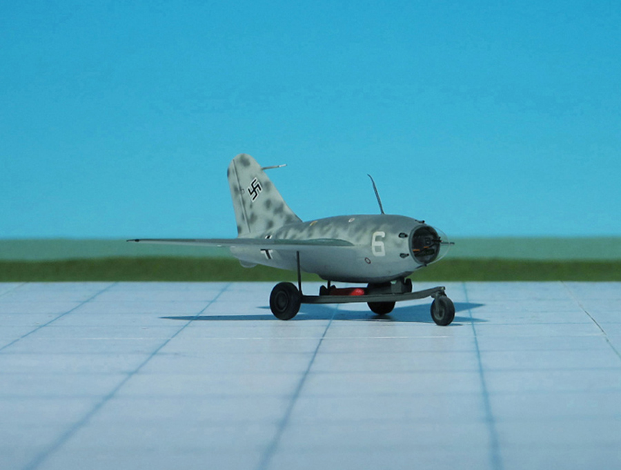
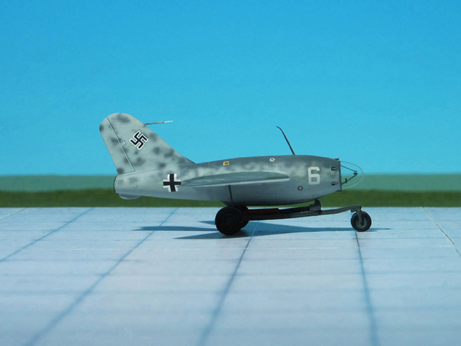
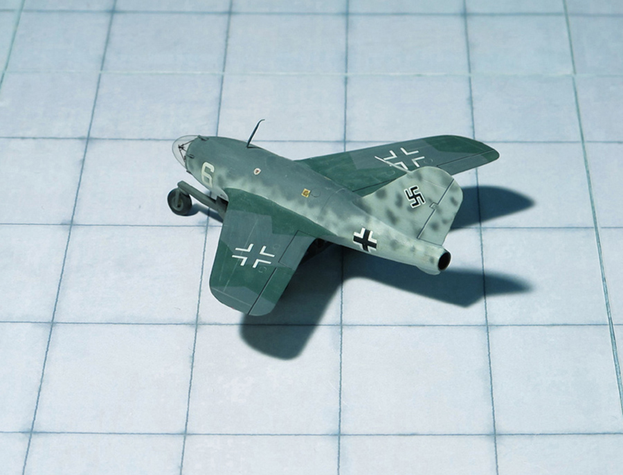
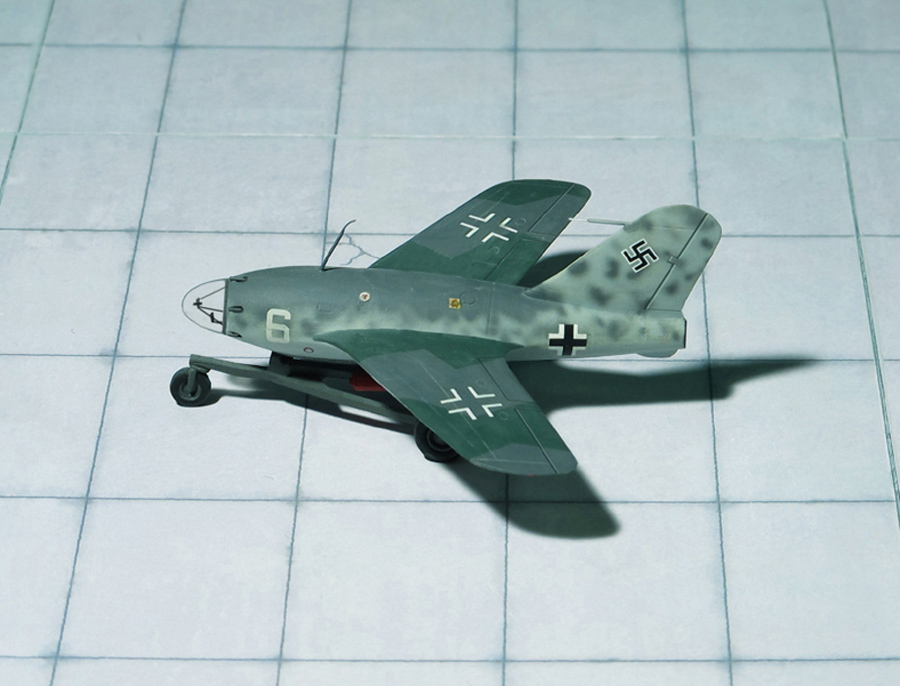
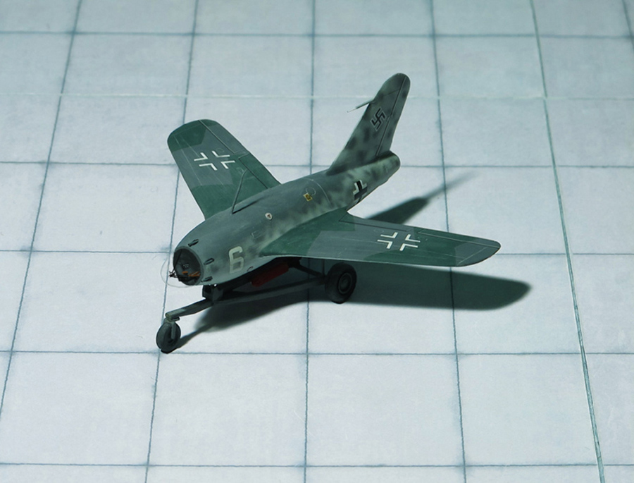
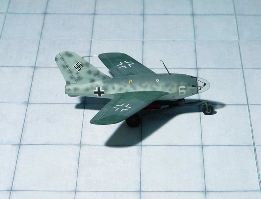
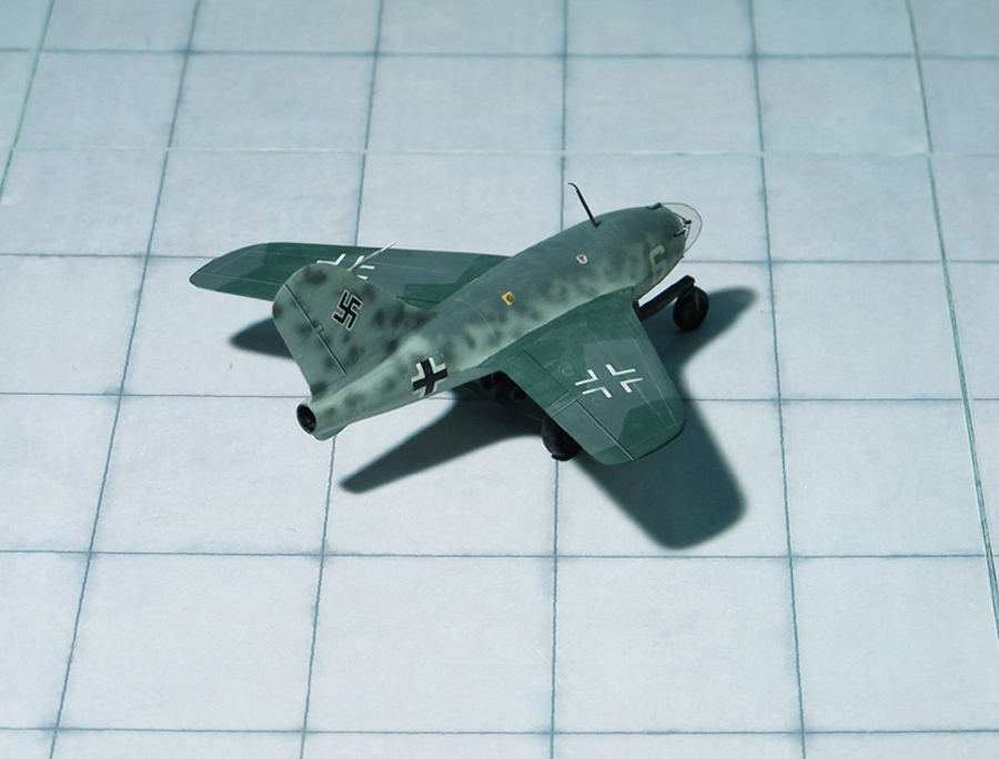
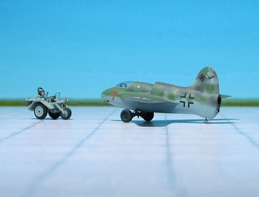
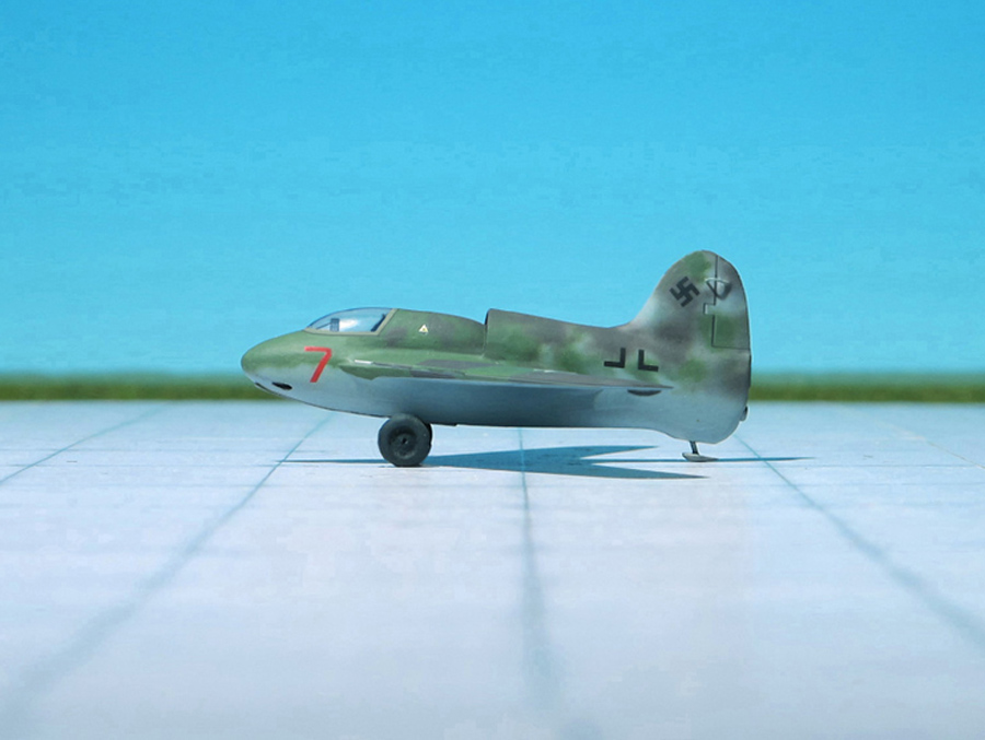
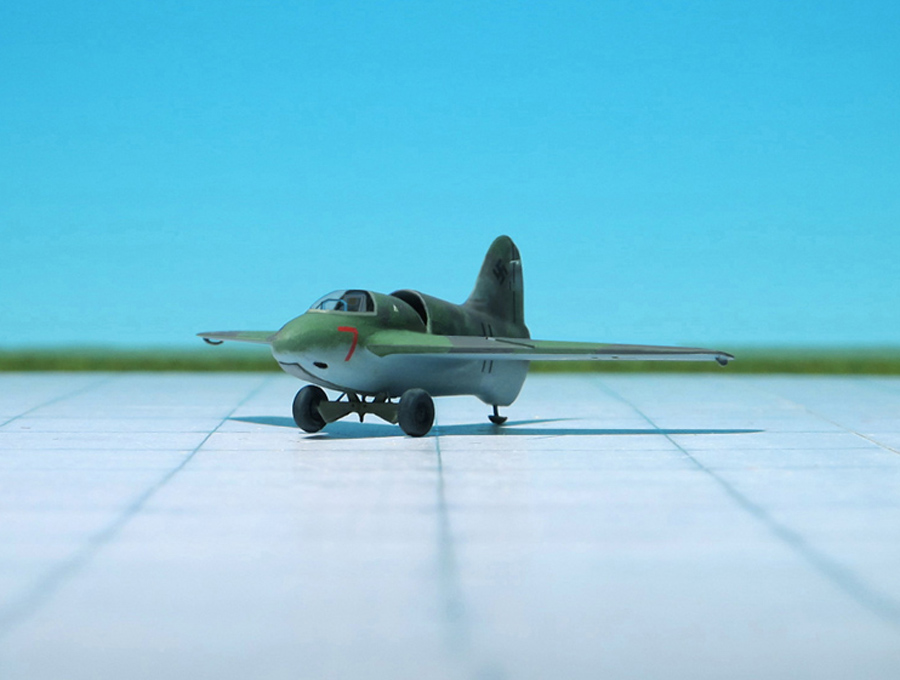
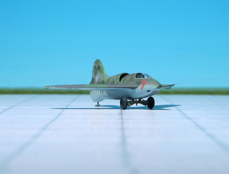
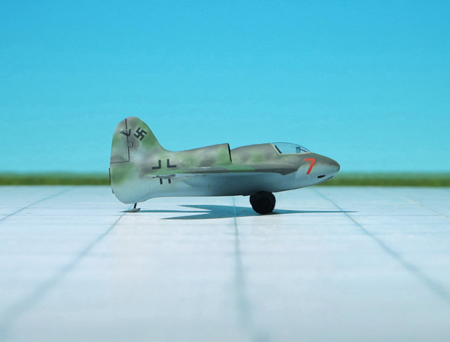
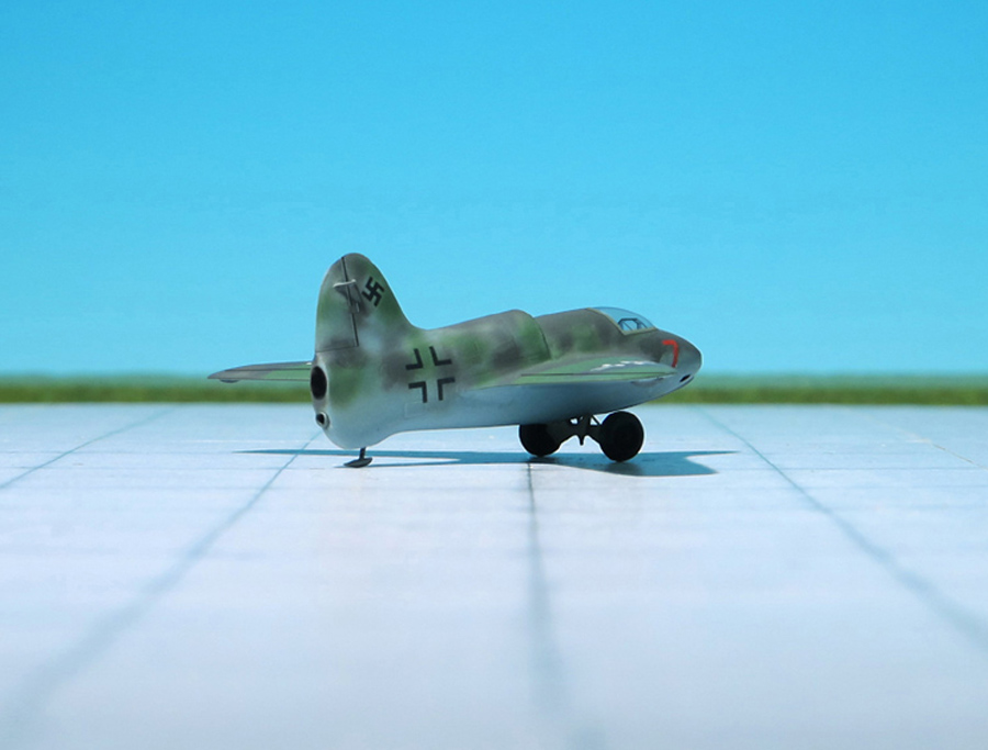
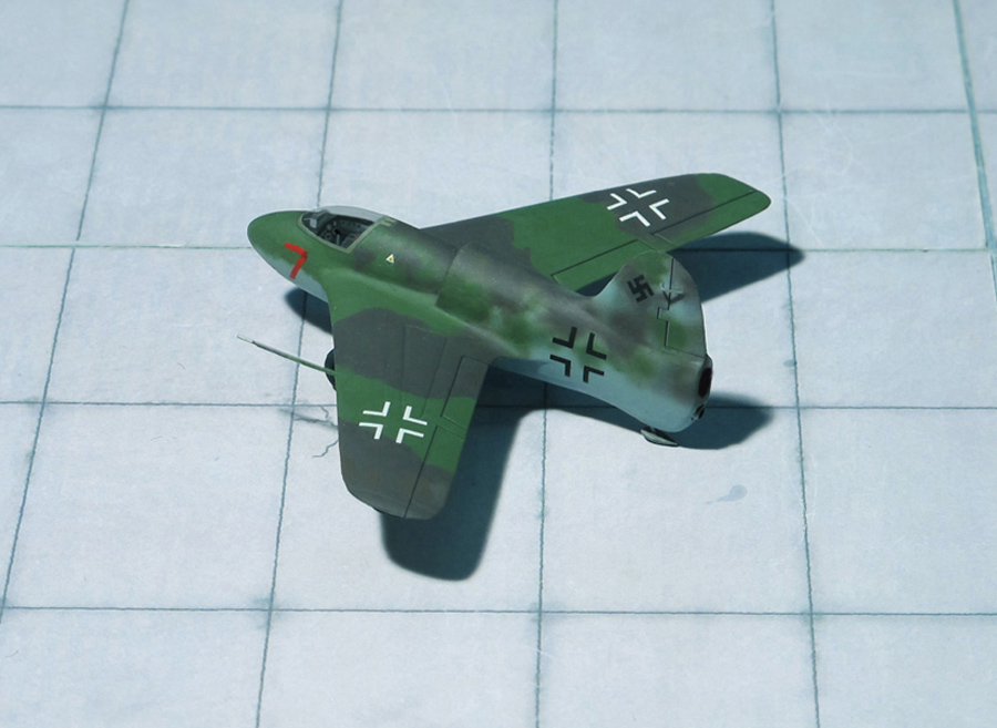
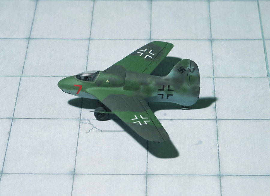
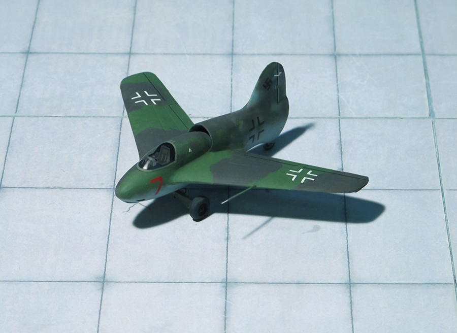
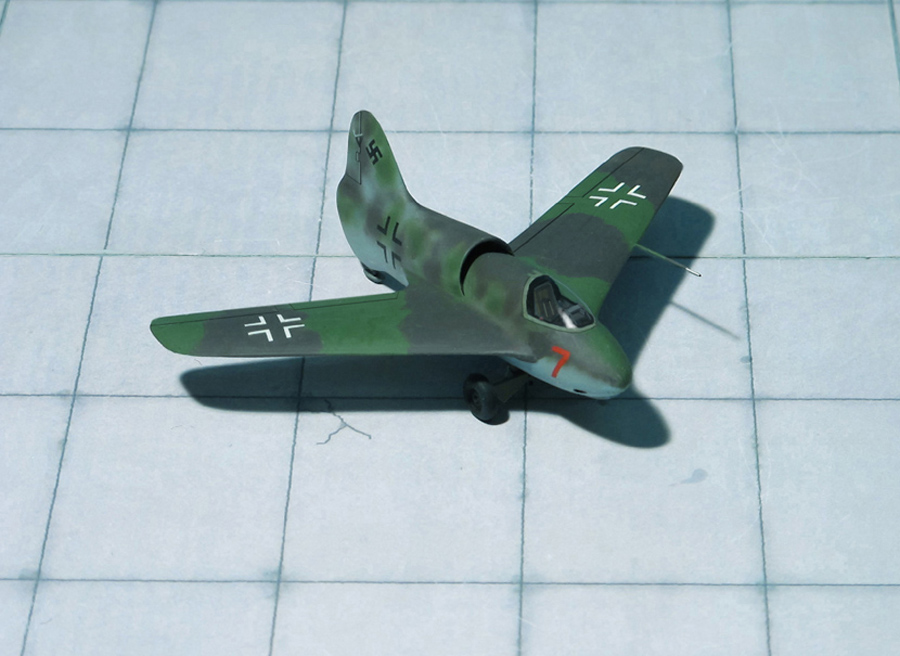
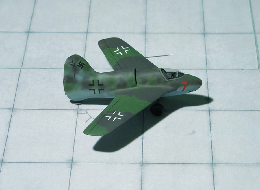
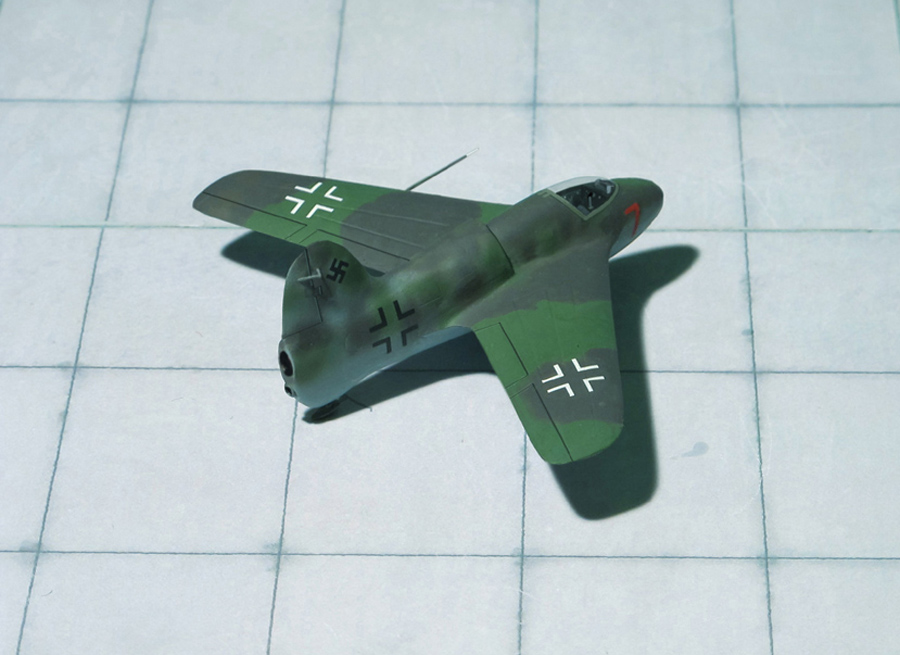
POWER PLANT: One BMW 109-510 or one Walter HWK 109-509 liquid-fuel rocket engine, each rated between 300 and 1,500 kp thrust
PERFORMANCE: 550 mph (estimated)
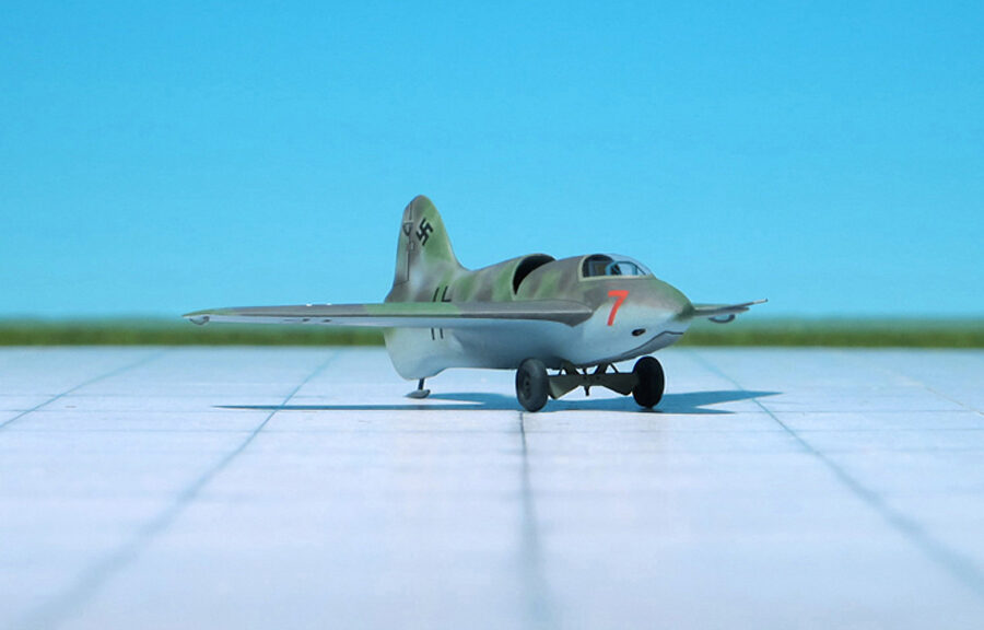
COMMENT: This Lippisch Li P.01-117 project dates from July and August 1941 after Alexander Lippisch and his design team moved to the Messerschmitt A.G. in Augsburg in early 1939. At that time a trio of Lippisch Li P. 01 designs were conceptualized within three weeks – the P.01-117 on July 22, the P.01-118 on August 3 and the P.01-119 on August 4.
The first design P.01-117 featured a cockpit where the pilot laid on a couch, chin up and head forward, the second boasted a novel tilting seat arrangement to improve the pilot’s visibility during a steep near-vertical climb, and the third had a pressure cabin for high altitude operations. Each of them was to be powered by a BMW or Walter HWK rocket engine but only the P.01-118 also had a second rocket engine to provide greater endurance for level flight. From this point on, all mention of the P.01 ceased and the project continued as the Messerschmitt Me 263.
The Lippisch Li P.01-117 was a tailless aircraft, with a swept wing at approximately 35 degrees. The overall plan resembled the later Messerschmitt Me 163 “Komet” rocket-powered fighter. The fuselage held the fuel tanks and a rocket engine was mounted in the rear fuselage. A pressurized cockpit was located in the aircraft’s extreme nose, and the pilot faced the front in a prone position and looked out through a blister of bulletproof glass. Up to six MG 151/20 20mm cannon were mounted around the nose of this aircraft. Take-off was accomplished by means of a releasable trolley, sometimes additionally boosted by two solid fuelled Schmidding 109-563 take-off rockets with 500 kp thrust each. Additional jettisonable solid-fuelled rockets could be attached to the fuselage. Landing was to be accomplished on a retractable skid, as was later done on the Messerschmitt Me 163. This design went no further than the preliminary design phase, but the Messerschmitt Me 163 went into production and was used operationally by the Luftwaffe (Ref.: 20).
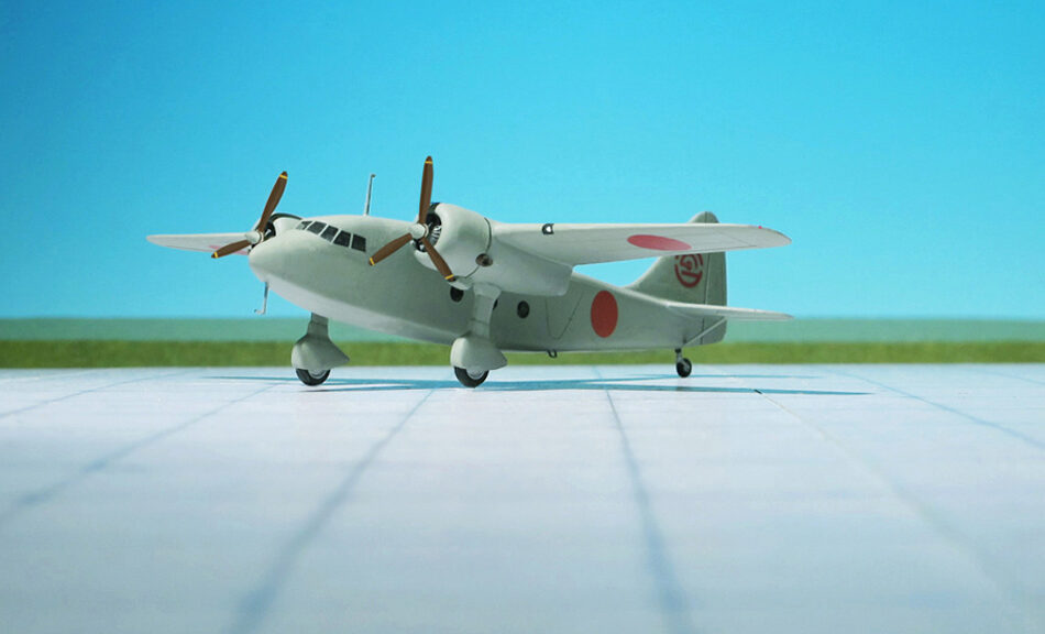
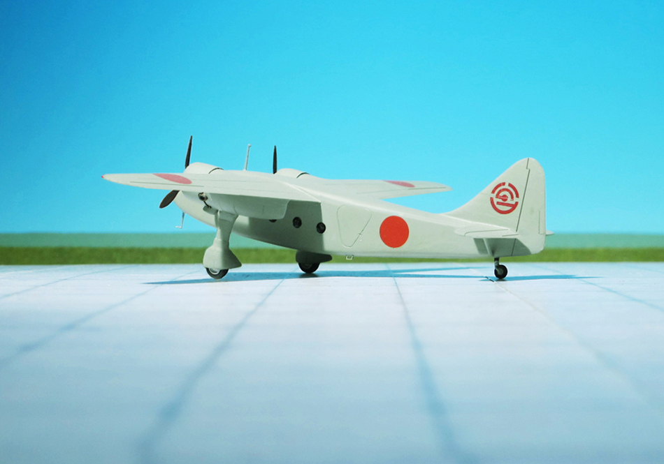
ACCOMMODATION: Crew of three plus eight passengers
POWER PLANT: Two Hitachi Ha-13a radial engine , rated at 450 hp each
PERFORMANCE: 186 mph
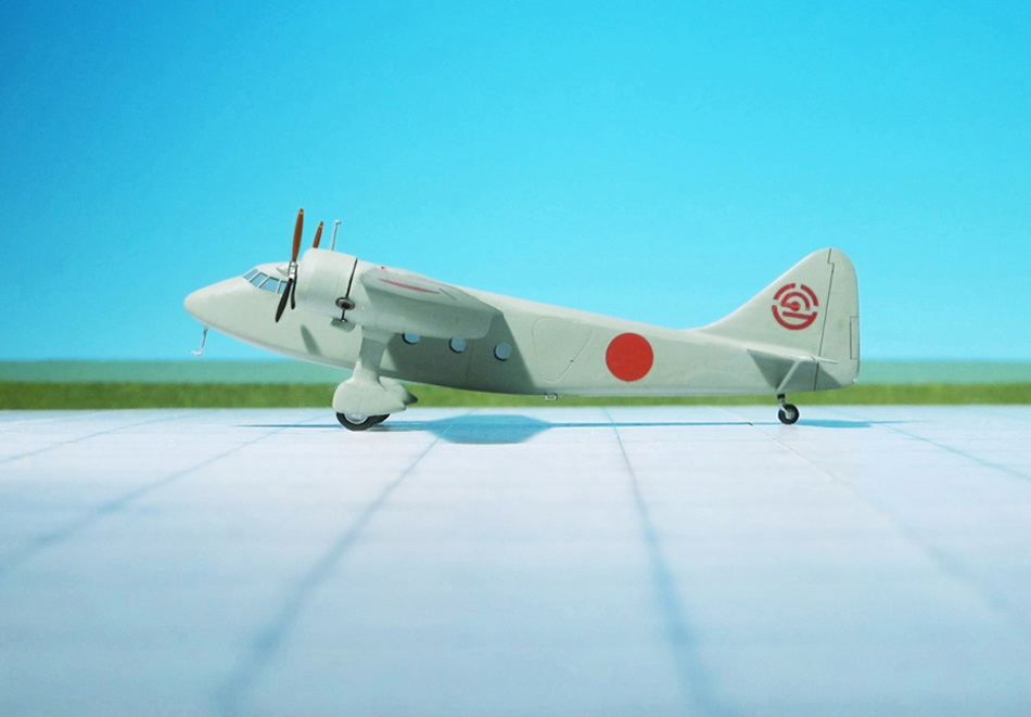
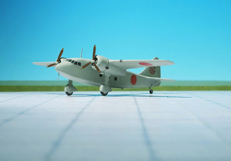
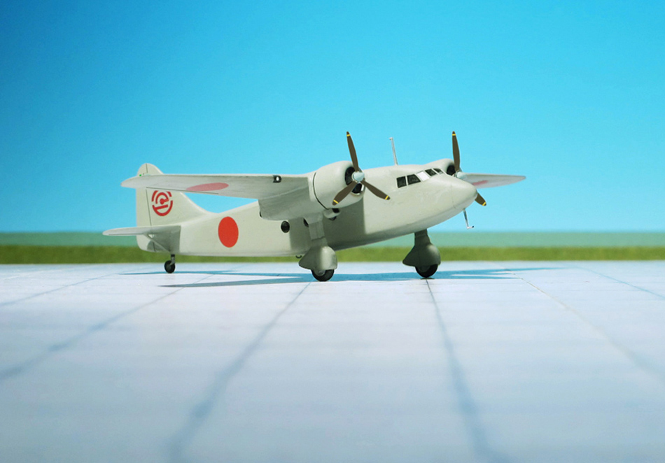
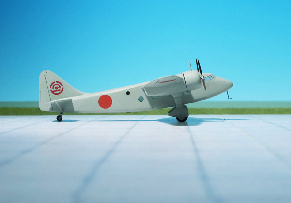
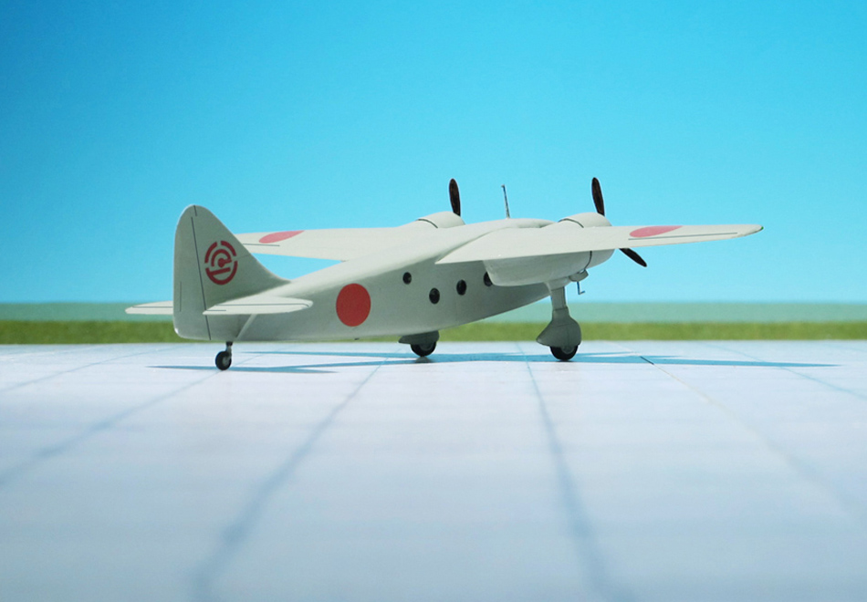
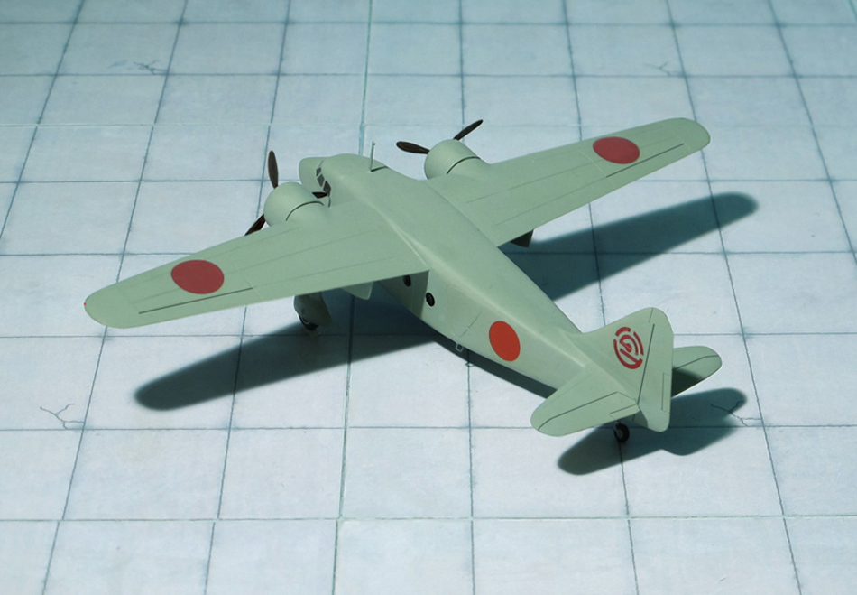
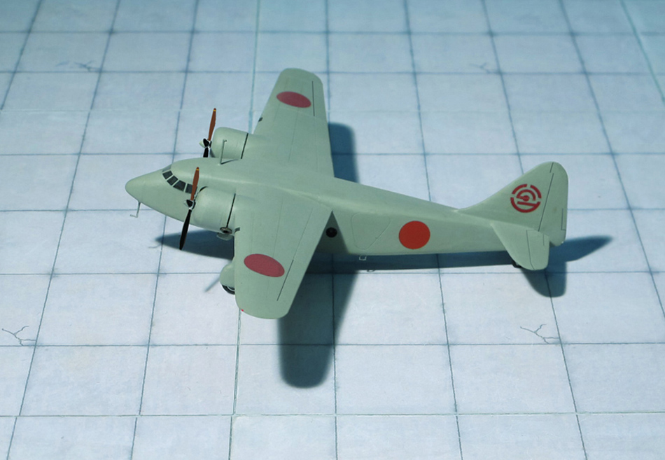
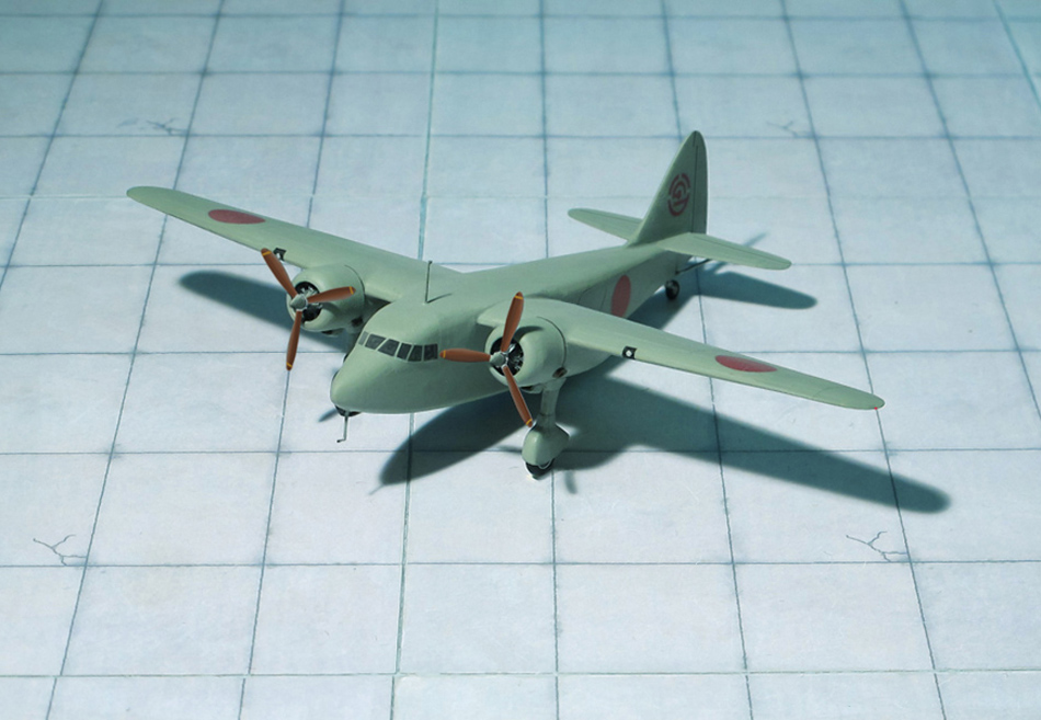
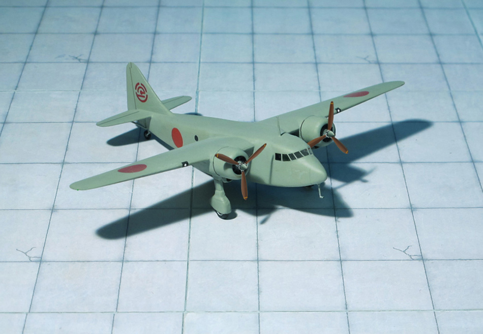
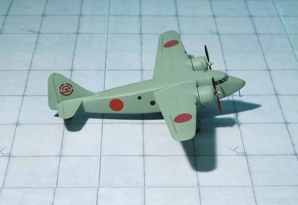
COMMENT: The Kokusai Ki-59 was an early 1940s light transport monoplane built by Nippon Kokusai Koku Kogyo K.K. for the Imperial Japanese Army as a development of the Teradako-ken TK-3 which had first flown in 1938.
The Teradako-ken TK-3 was a prototype eight-to-ten passenger light transport monoplane built by Nippon Koku Kogyo Kabushiki Kaisha as a short-range transport for civil use at the request of Imperial Japanes Airways to replace its aging fleet of Airspeed Envoys and Fokker Super Universals. The first of two prototypes flew in June 1938, but was unable to meet the required performance requirements and the project was cancelled. In 1939, the Imperial Japanese Army revived the project to meet its urgent requirement for a light transport and liaison aircraft and instructed Nippon to develop the design as the Ki-59.
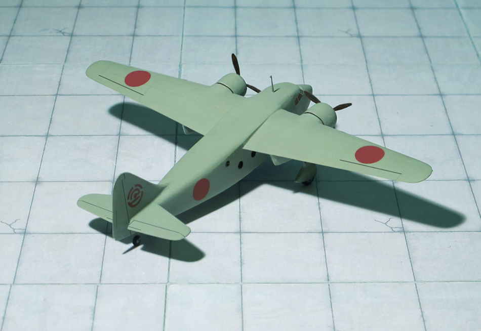
The Ki-59 was a high-wing cantilever monoplane with a fixed tailwheel landing gear and conventional single vertical tail surfaces. It was powered by two 450 hp Hitachi Ha-13a radial engines and other modifications to the design were made to meet Army requirements. The Ki-59 was ordered into production in 1941 with the designation Army Type 1 Transport, and an additional 59 units were produced. After the start of World War II, the aircraft was given the Allied reporting name „Theresa“. Despite the more powerful engines and modifications sponsored by the Japanese Army, the Ki-59 remained a poor performer and saw little service before being replaced by the more capable Tachikawa Ki-54. A small number were transferred to Manchukuo National Airways.
Near the end of 1941 one Ki-59 was modified into a glider with the removal of the engines and the landing gear replaced by underfuselage skids. It was designated the Ku-8-I or Army Experimental Glider. This was further developed as the Ku-8-II or Army Type 4 Large Transport Glider which became the only operationally used Japanese assault glider. It was named „Gander“ by the Allies (Ref.: 24).
Kokusai Ki-59 („Theresa“), Hamamatsu Army Bomber School
Kokusai Ki-59 („Theresa“), Hamamatsu Army Bomber School
Kokusai Ki-59 („Theresa“), Hamamatsu Army Bomber School
Kokusai Ki-59 („Theresa“), Hamamatsu Army Bomber School
Kokusai Ki-59 („Theresa“), Hamamatsu Army Bomber School
Kokusai Ki-59 („Theresa“), Hamamatsu Army Bomber School
Kokusai Ki-59 („Theresa“), Hamamatsu Army Bomber School
Kokusai Ki-59 („Theresa“), Hamamatsu Army Bomber School
Kokusai Ki-59 („Theresa“), Hamamatsu Army Bomber School
Kokusai Ki-59 („Theresa“), Hamamatsu Army Bomber School
Kokusai Ki-59 („Theresa“), Hamamatsu Army Bomber School
Kokusai Ki-59 („Theresa“), Hamamatsu Army Bomber School
POWER PLANT: One BMW P-3304/109-002 turbojet engine and an undetermined Walter rocket engine, thrust of each engine unknown
PERFORMANCE: No data available
COMMENT: The Lippisch Li P.01-115 was another design under the Li P.01 series, all designed by Alexander Lippisch and his team while at Messerschmitt A.G.
Dated July 2, 1941, the Li P.01-115 had a similar plan form to the others in the P.01 series (which were similar to the Messerschmitt Me 163 rocket fighter). The fuselage held the armament, fuel and power plants. This was one of the first designs to feature a dual powered fighter. A small BMW P-3304/109-002 turbojet engine was located in the upper rear fuselage and was fed by an air intake on top of the fuselage. In addition, a BMW 109-510 rocket engine was mounted beneath the turbojet and provided takeoff and perhaps emergency power. The wings were swept back at 27 degrees, and only a single vertical tail and rudder was to be fitted. In this tailless configuration, the pilot sat in a cockpit in the front of the plane. For take-off, a pair of wheels, each mounted onto the ends of a specially designed cross-axle, were needed due to the weight of the fuel, but the wheels, forming a take-off dolly under the landing skid, were released shortly after take-off. and landing was accomplished on a retractable skid. Two forward-firing fixed MG 151 15mm cannon located in the forward lower fuselage comprised the armament.
As with other designs in the Lippisch P.01 series, this design went no further than the drawing board stage. All work was later devoted to the Messerschmitt Me 163 “Komet” and later variant rocket fighters (Ref.: 20).
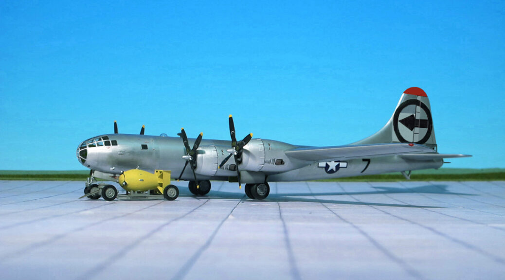
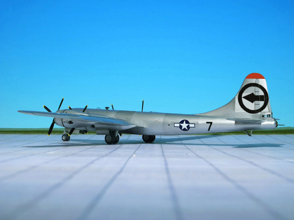
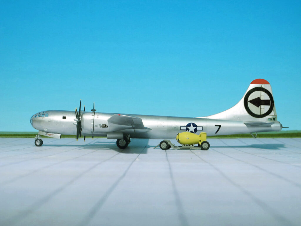
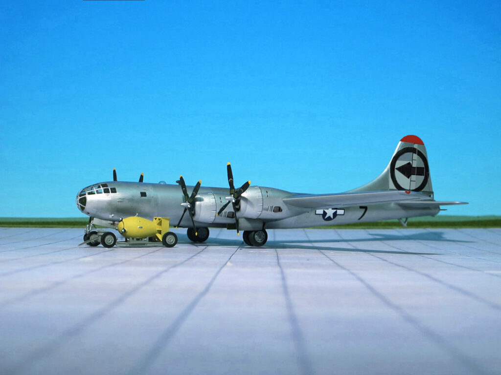
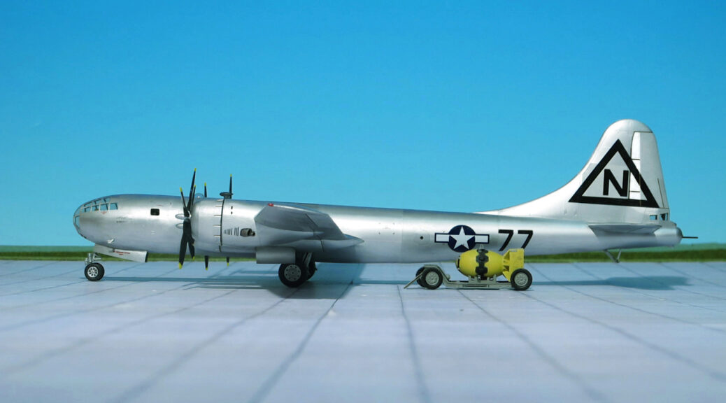
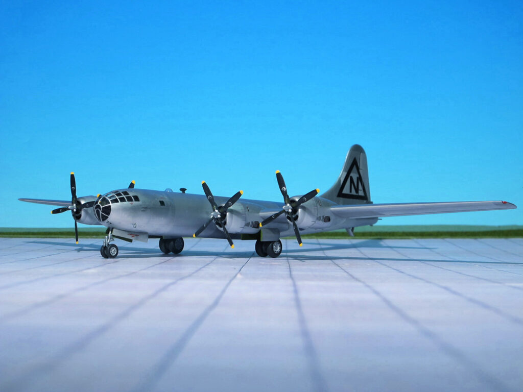
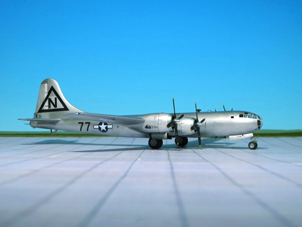
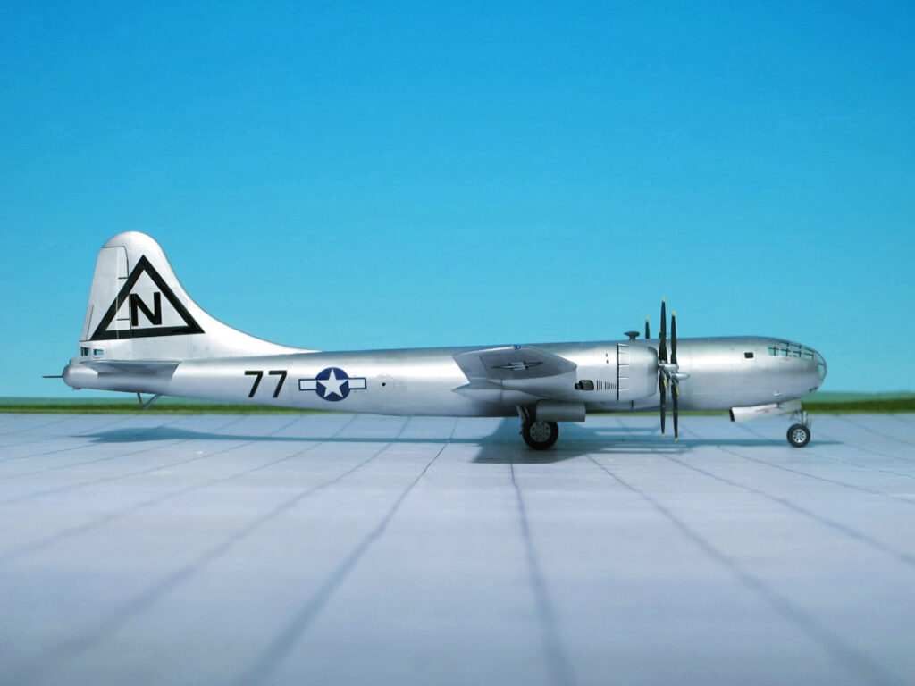
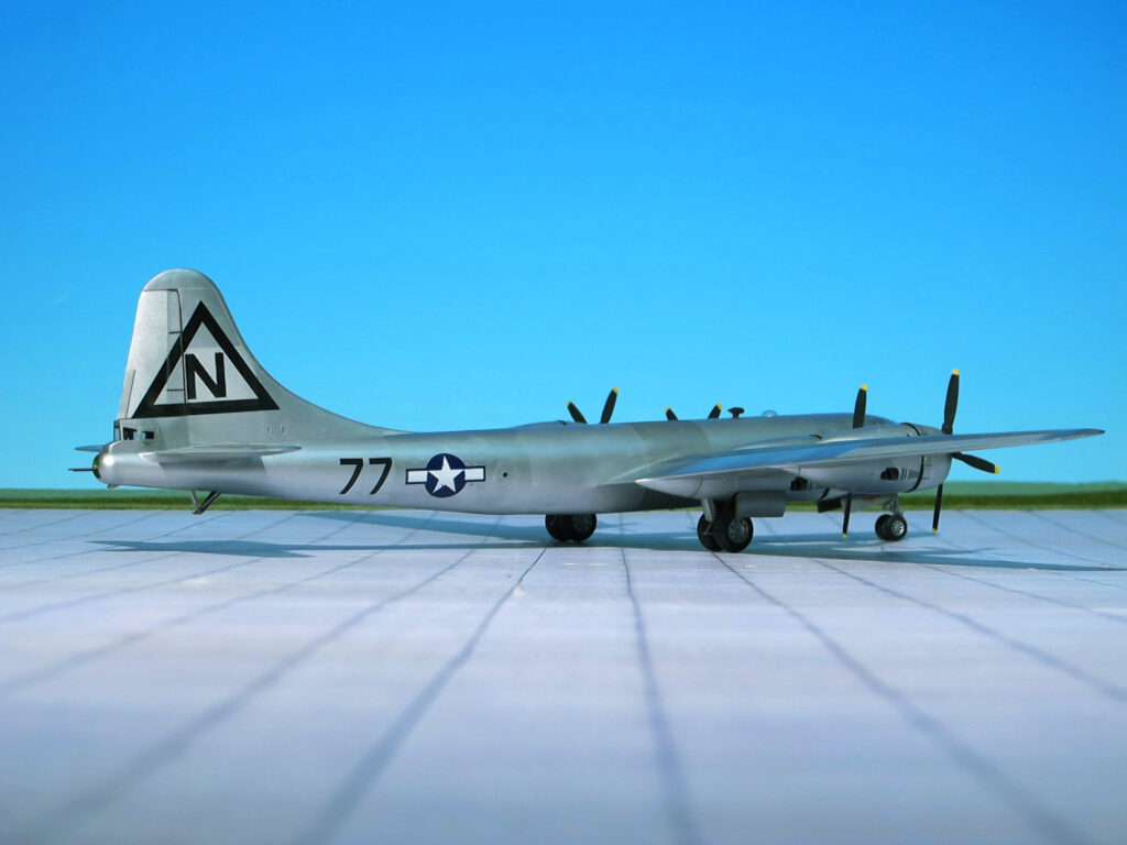
Bockscar, sometimes called Bock’s Car, is the name of the United States Army Air Force (USAAF) Boeing B-29 bomber that dropped a Fat Man, a plutonium implosion-type nuclear weapon, over the Japanese city of Nagasaki during World War II in the second – and most recent – nuclear attack in history. Bockscar, B-29-36-MO 44-27297, Victor number, (unit-assigned identification number) # 7, was built by the Glenn L. Martin Company at its bomber plant in Bellevue, Nebraska and one of 15 Silverplate B-29, a Block 35 aircraft, after modification re-designated “Block 36”. It was delivered to the United States Army Air Forces on 19 March 1945 and in April assigned to the 393rd Bombardment Squadron, 509th Composite Group to Wendover Army Air Field, Utah, and was named after Captain Frederick C. Bock.
Silverplate involved extensive modifications to the B-29 to carry nuclear weapons. The bomb bay doors and the fuselage section between the bomb bays were removed to create a single 33-foot bomb bay. British suspensions and bracing were attached for both shape types, with the gun-type (Little Boy) suspension anchored in the aft bomb bay and the implosion type (Fat Man) mounted in the forward bay. Weight reduction was also accomplished by removal of gun turrets and armor plating. These B-29s also had an improved engine, the Wright R-3350-41. The Silverplate aircraft represented a significant increase in performance over the standard variants.
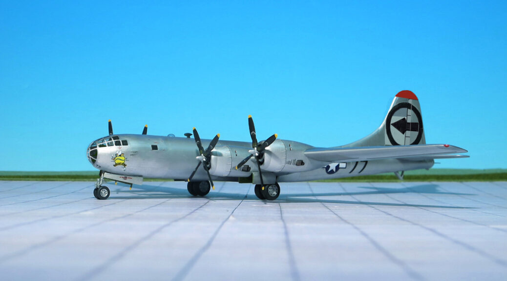
Captain Frederick C. Bock and crew C-13, flew to Wendover Army Air Field in April. The name chosen for the aircraft, and and the nose art painted on it after the mission, was a pun on the name of the aircraft commander. It left Wendover on 11 June 1945 for Tinian, where it arrived 16 June. It was originally given a circle outline around an arrowhead pointing forward tail marking as used by the 509th Composite Group. Bockscar was used in 13 training and practice missions from Tinian, and three combat missions in which it dropped Pumpkin bombs on industrial targets in Japan, in which Bock’s crew bombed Niihama, Musashimo and Koromo.
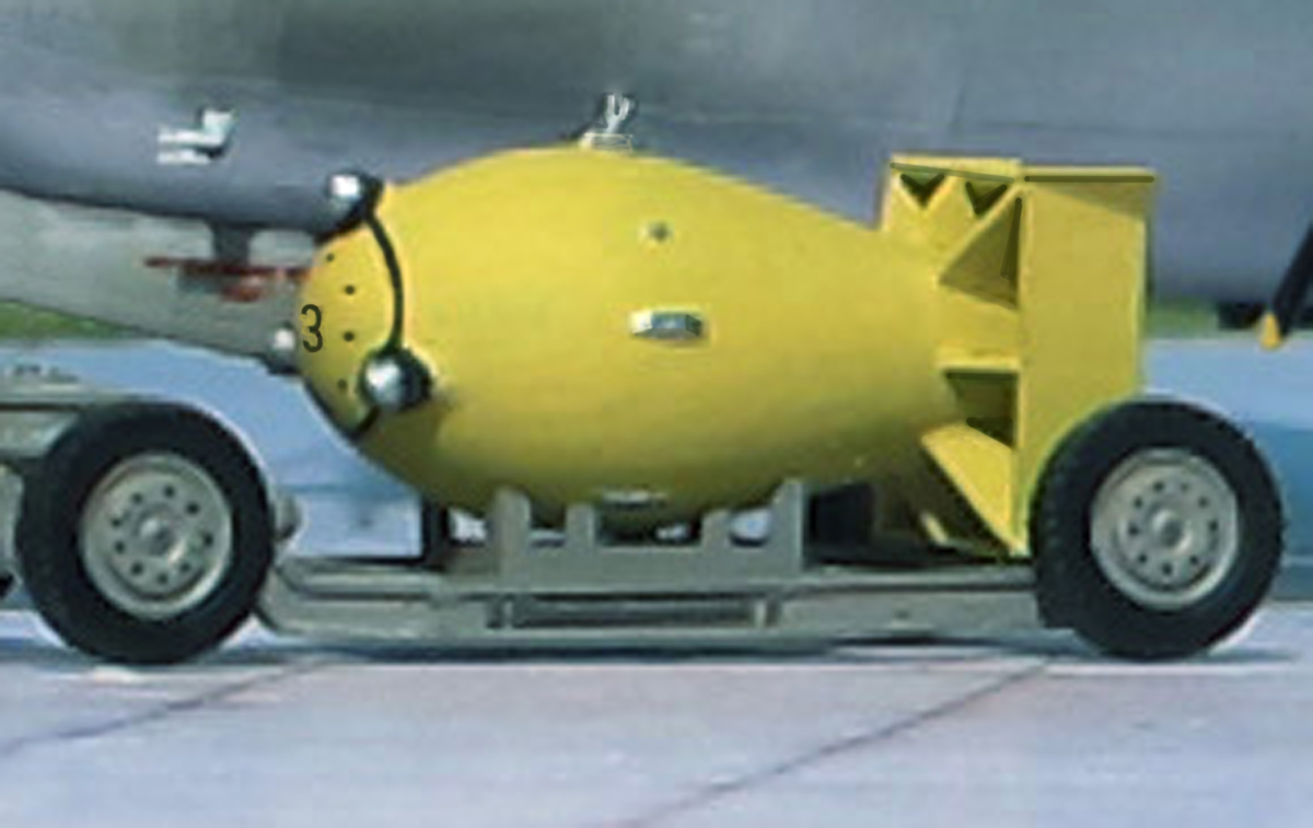
Pumpkin bomb
PUMPKIN BOMBS
„Pumpkin bombs“ were conventional aerial bombs developed by scientists of the Manhattan Project and used by the United States Army Air Forces against Japan during WW II. It was a close replication of the „Fat Man“ plutonium bomb with the same ballistic and handling characteristics, but it used non-nuclear conventional high explosives. It was mainly used for testing and training purposes, which included combat missions flown with pumpkin bombs by the 509th Composite Group. The name “pumpkin bomb” was the term used in official documents from the large, fat ellipsoidal shape of the munition casing instead of the more usual cylindrical shape of other bombs, intended to enclose the „Fat Man’s“ spherical “physics package” (the plutonium implosion nuclear weapon core).
„Pumpkin bombs“ were produced in both inert and high-explosive variants. The inert versions were filled with a cement-plaster-sand mixture that was combined with water to 1.67 to 1.68 grams per cubic centimetre, the density of the composition high-explosive versions. The filler of both variants had the same weight (2,900 kg) and weight distribution as the inner spherical “physics package” of the „Fat Man“ plutonium bomb.
A total of 486 live and inert training bombs were eventually delivered, the 509th Composite Group dropped a total of 49 bombs on 14 Japanese targets (Ref. 24).
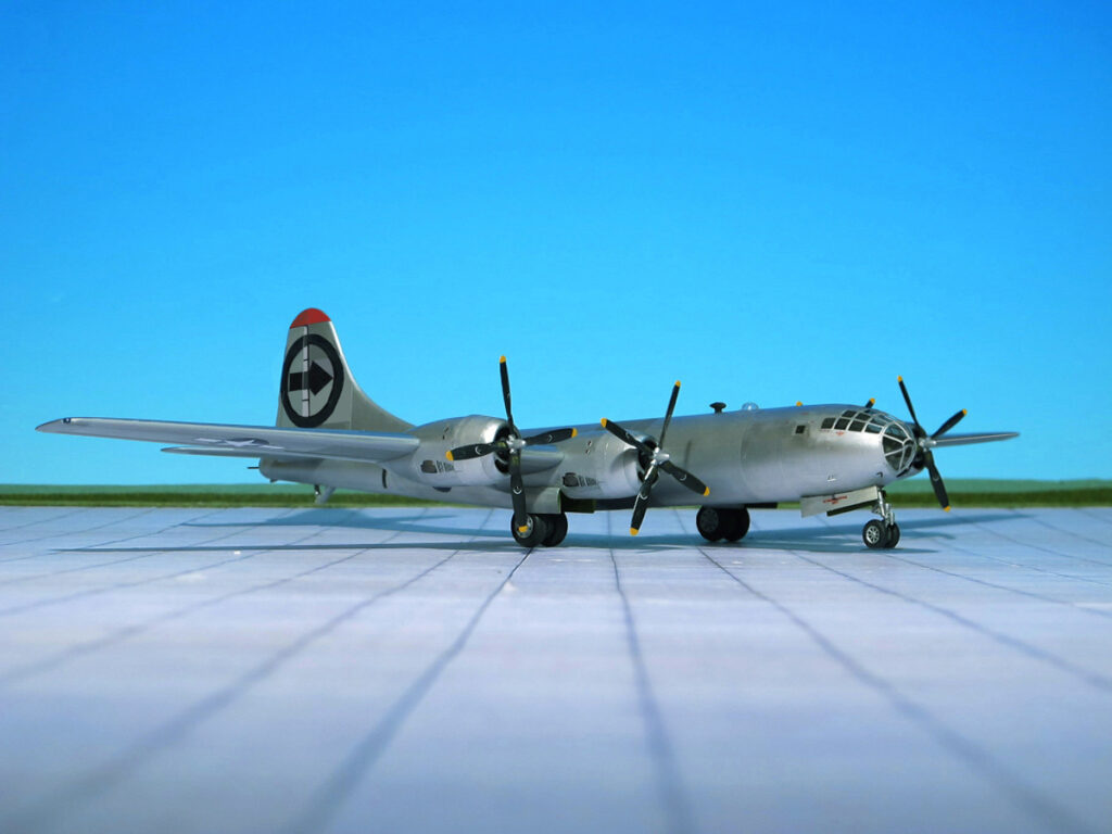
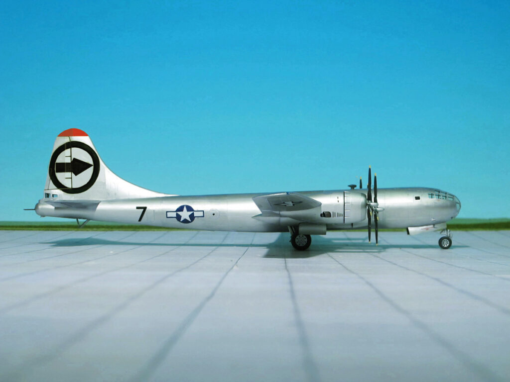
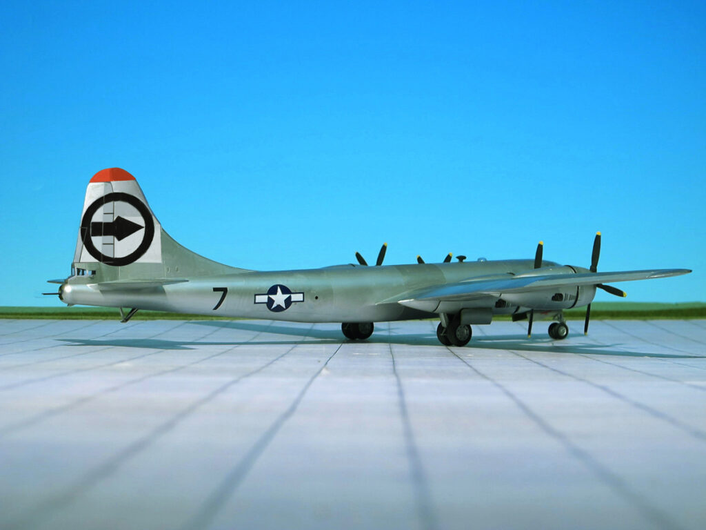
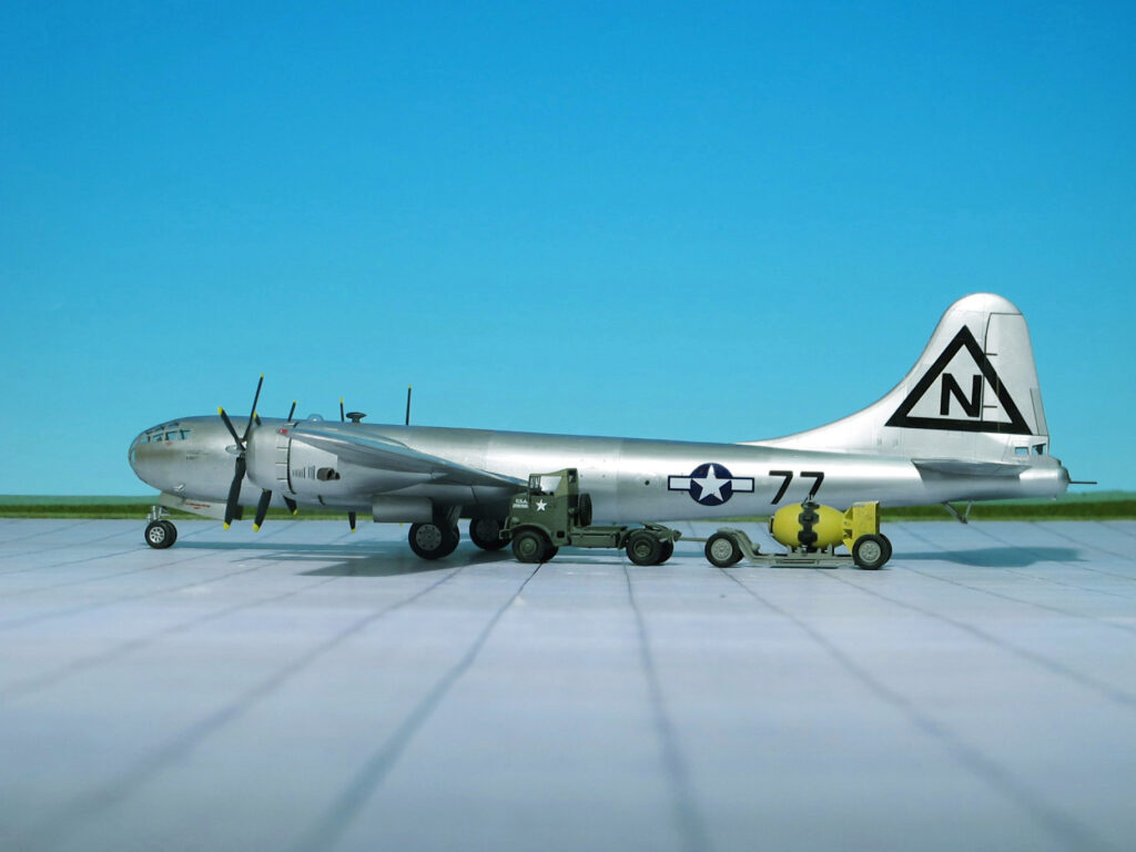
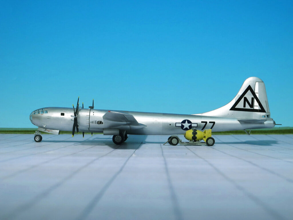
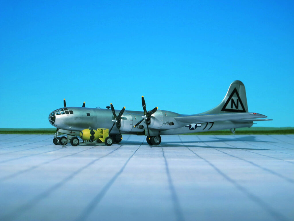
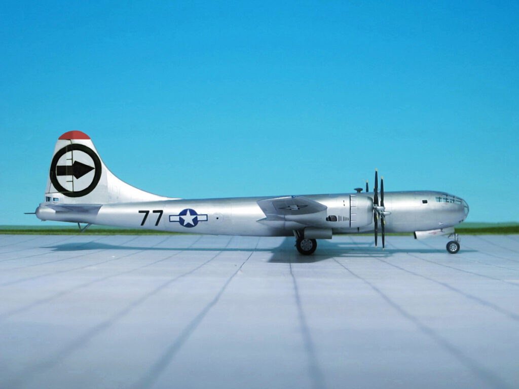
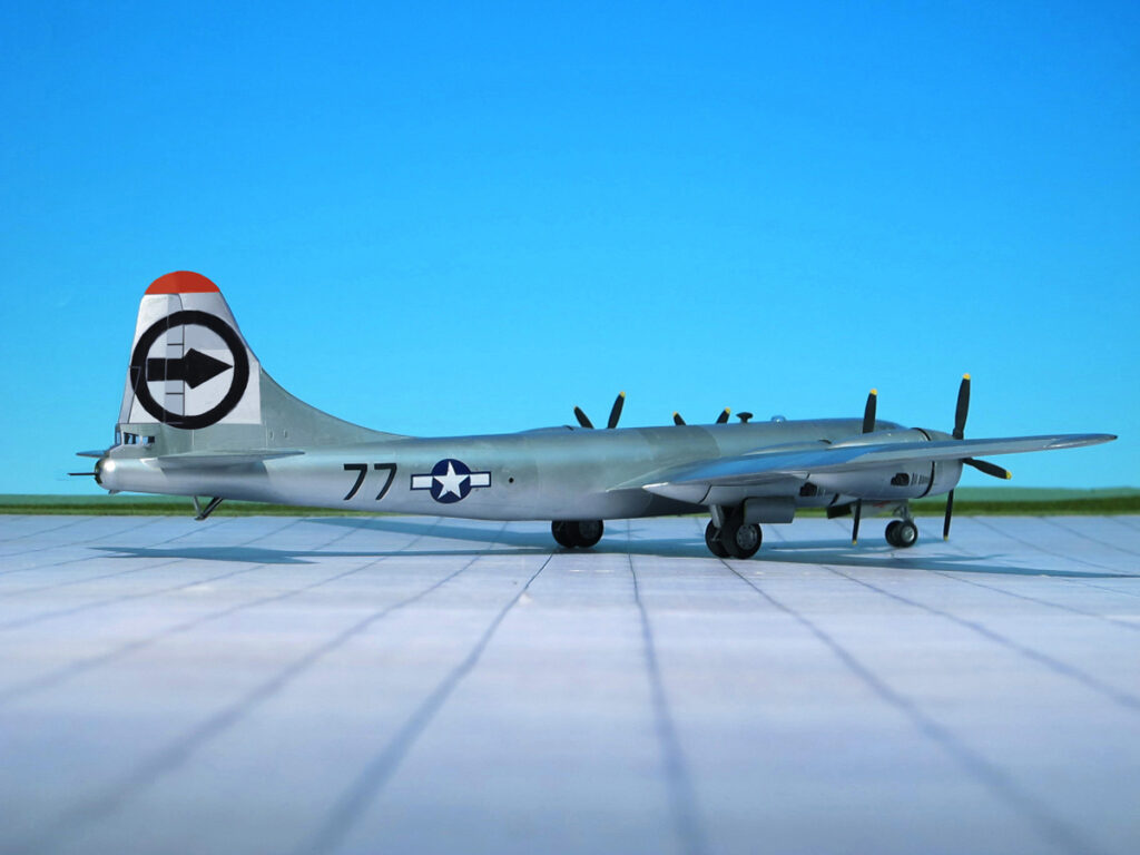
Boeing B-29 Superfortress ‘Bockscar’, 393rd Bombardment Squadron, 509th Composite Group. Before the Nagasaki Mission
Boeing B-29 Superfortress ‘Bockscar’, 393rd Bombardment Squadron, 509th Composite Group. Before the Nagasaki Mission
Boeing B-29 Superfortress ‘Bockscar’, 393rd Bombardment Squadron, 509th Composite Group. Before the Nagasaki Mission
Boeing B-29 Superfortress ‘Bockscar’, 393rd Bombardment Squadron, 509th Composite Group. Before the Nagasaki Mission
Boeing B-29 Superfortress ‘Bockscar’, 393rd Bombardment Squadron, 509th Composite Group. Before the Nagasaki Mission
Boeing B-29 Superfortress ‘Bockscar’, 393rd Bombardment Squadron, 509th Composite Group. Before the Nagasaki Mission
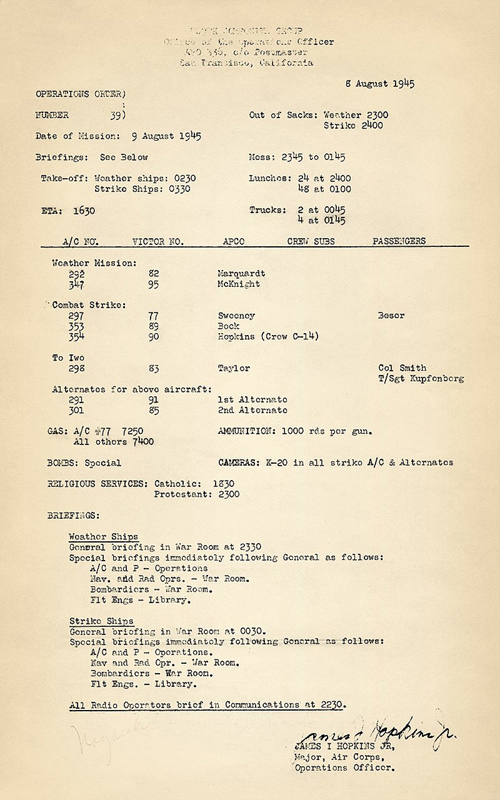
On 8 August 1945, the Strike Order # 39 was given to deliver the second atomic bomb Fat Man the next day on 9 August. This order gives the detailed time scale of the pre-flight preparations and all aircraft involved in the attack as well as the names of the aircraft‘s commanding officers. This time the combat strike consisted of three aircraft, one alternative plane stationed at Iwo Iima to take over the atomic bomb in case of failures of Bockscar and two weather mission aircraft including the Enola Gay latter flown by Captain George W. Marquardt plus two alternative aircraft . Weather Ships had to start at 0230 ET, while the strike Ships followed one hour later. Victor # 77 was the Bockscar with Major Sweeney at the controlls.. The Bombload simply mentioned „Special“, primary target was Nagasaki.
Strike Order Nagasaki
ATOMIC BOMB “FAT MAN”
“Fat Man” was 3.4 m, in length, 1.5 m in diameter and weighed 9,100 kg. The design was an implosion-type weapon using plutonium. A subcritical sphere of plutonium was placed in the center of a hollow sphere of high explosive. Numerous detonators located on the surface of the sphere were fired simultaneously to produce a powerful inward pressure on the capsule, squeezing it and increasing its density. This resulted in a supercritical condition and a nuclear explosion.
The bomb had an explosive force of about 20,000 tons of TNT, about the same as the bomb dropped on Hiroshima. Because of Nagasaki’s hilly terrain, however, the damage was somewhat less extensive than of the relatively flat Hiroshima
Three Fat Man high explosive pre-assemblies designated F31, F32, and F33 were transported to North Field, arriving 2 August. F33 was expended during the final rehearsal on 8 August, and F31 was the bomb dropped on Nagasaki. F32 presumably would have been used for a third attack or its rehearsal.
Atomic bomb ‘Fat Man’ Mk III
STRIKE ON NAGASAKI, DATE: AUGUST, 9th, 1945
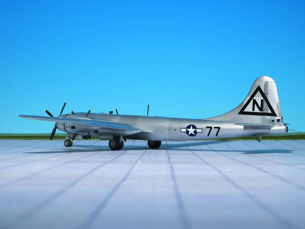
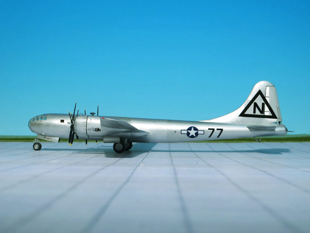
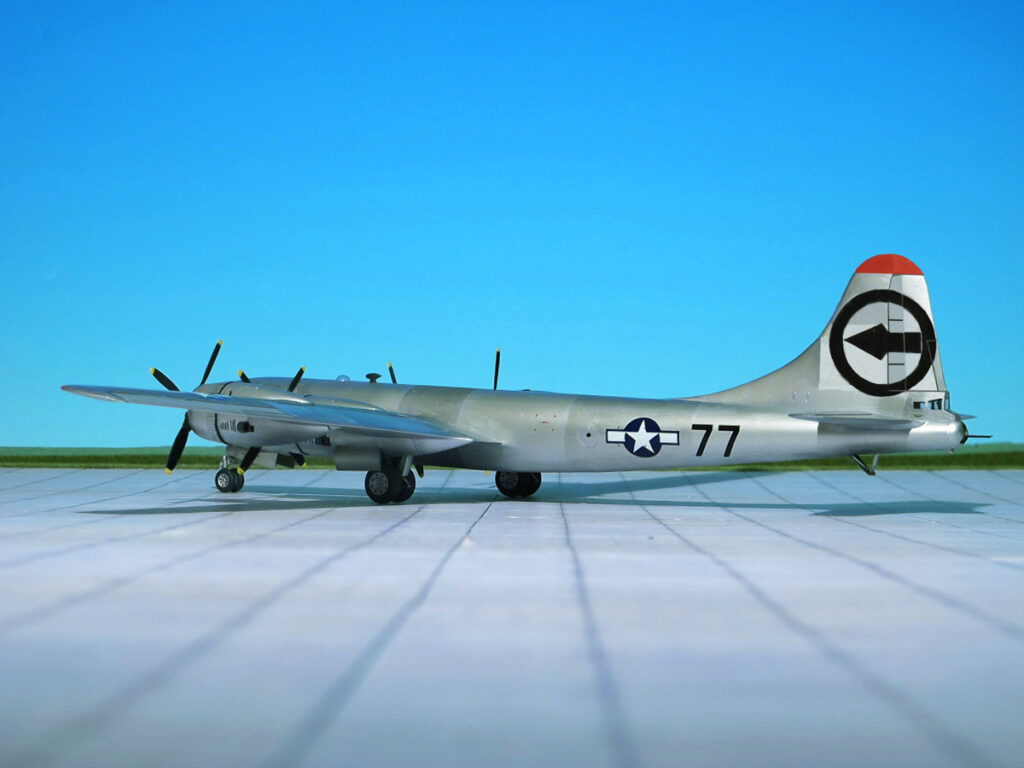
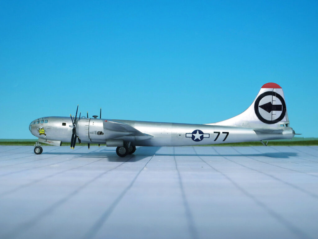
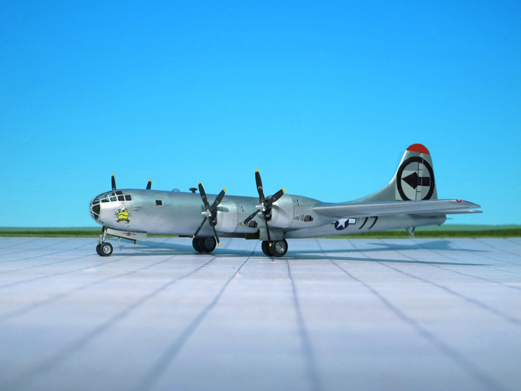
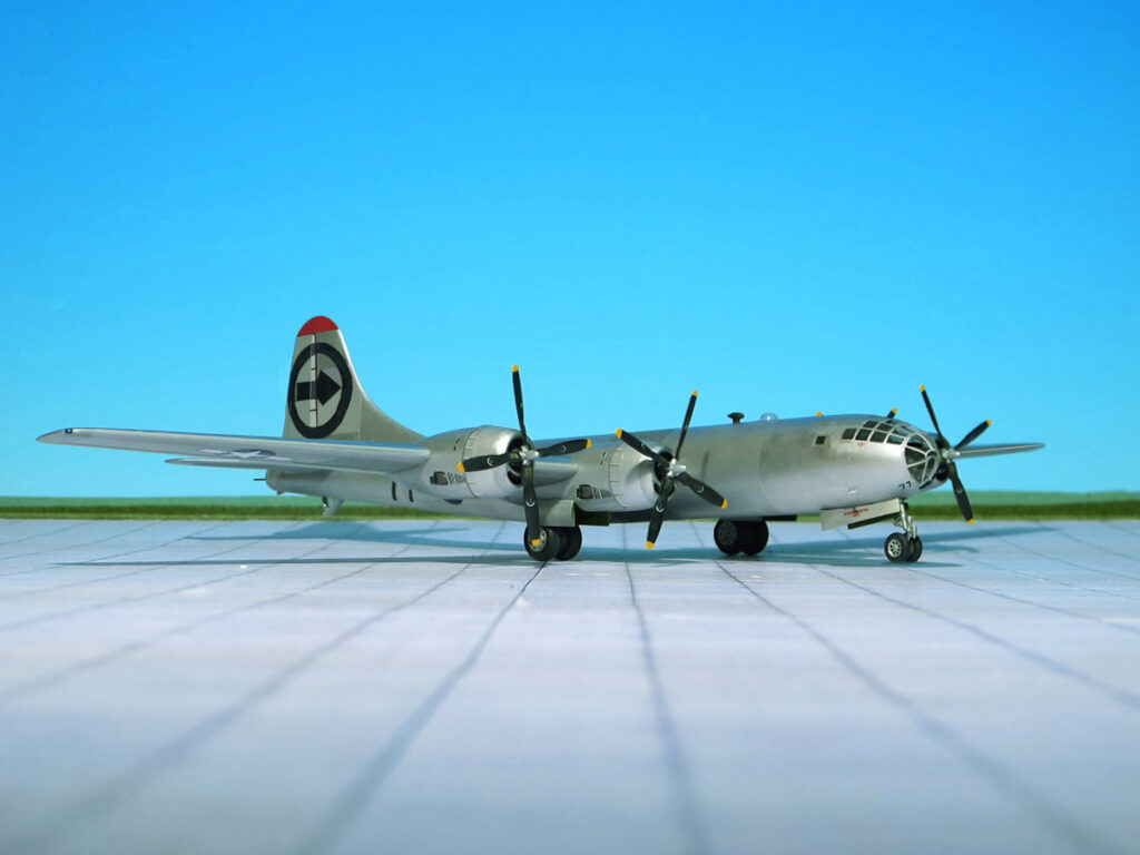
On 1 August the aircraft was given the triangle N tail markings of the 444th Bombardment Group as a security measure, and had its Victor number changed to # 77 to avoid misidentification with an actual 444th aircraft. Except for Enola Gay, none of the 509th Composite Group B-29s had yet had names or nose art painted on the noses. All other names were given or painted after the mission.
The mission included three B-29 bombers and their crews: # 77 Bockscar, # 89 The Great Artiste and # 50 The Big Stink. Bockscar was flown on 9 August 1945 by Crew C-15, which usually manned The Great Artiste; piloted by Major Charles W. Sweeney, commander of the 393rd Bombardment Squadron; and co-piloted by First Lieutenant Charles Donald Albury, C-15’s aircraft commander. The Great Artiste– flown by Captain Frederick C. Bock – was designated as an observation and instrumentation support plane for the second mission, while The Big Stink – flown by group operations officer Major James I. Hopkins Jr. – as a photographic aircraft. The primary target was the city of Kokura, where the Kokura Arsenal was located, and the secondary target was Nagasaki, where two large Mitsubishi armament plants were located. Bockscarhad been flown by Sweeney and crew C-15 in three test drop rehearsals with inert pumpkin bomb assemblies in the eight days leading up to the second mission, including a final rehearsal the day before. The Great Artiste, which was the assigned aircraft of the crew with whom Sweeney usually flew, had been designated in preliminary planning to drop the second bomb, but the aircraft had been fitted with observation instruments for the Hiroshima mission that took place three days earlier. Moving the instrumentation from The Great Artiste to Bockscar would have been a complex and time-consuming process, and when the second atomic bomb mission was moved up from 11 to 9 August because of adverse weather forecasts, the crews of The Great Artiste and Bockscar instead changed aircraft. The result was that the bomb was carried by Bockscar but flown by the crew C-15 of The Great Artiste.
During pre-flight inspection of Bockscar, the flight engineer notified Sweeney that an inoperative fuel transfer pump made it impossible to use 640 US gallons of fuel carried in a reserve tank. This fuel would still have to be carried all the way to Japan and back, consuming still more fuel. Replacing the pump would take hours; moving the Fat Man to another aircraft might take just as long and was dangerous as well, as the bomb was live. Group Commander Colonel Paul Tibbets and Sweeney therefore elected to have Bockscar continue the mission. Bockscartook off from Tinian’s North Field at 03:49. The mission profile directed the B-29s to fly individually to the rendezvous point, changed because of bad weather from Iwo Jima to Yakushima Island, and at 17,000 feet cruising altitude instead of the customary 9,000 feet , increasing fuel consumption. Bockscar began its climb to the 30,000 feet bombing altitude a half-hour before rendezvous. Before the mission, Tibbets had warned Sweeney to take no more than fifteen minutes at the rendezvous before proceeding to the target. Bockscar reached the rendezvous point and assembled with The Great Artiste, but after circling for some time, The Big Stinkfailed to appear. As they orbited Yakushima, the weather planes Enola Gay (which had dropped the first atomic bomb on Hiroshima) and Laggin‘ Dragon reported both Kokura and Nagasaki within the accepted parameters for the required visual attack.
Though ordered not to circle longer than fifteen minutes, Sweeney continued to wait for The Big Stink, finally proceeding to the target only at the urging of Commander Frederich Ashworth, the plane’s weaponeer, who was in command of the mission. After exceeding the original departure time limit by a half-hour, Bockscar, accompanied by the instrument airplane,The Great Artiste, arrived over Kokura, thirty minutes away. The delay at the rendezvous had resulted in clouds and drifting smoke from fires started by a major firebombing raid by 224 B-29s on nearby Yahata the previous day covering 70% of the area over Kokura, obscuring the aiming point. Three bomb runs were made over the next 50 minutes, burning fuel and exposing the aircraft repeatedly to the heavy defenses of Yahata, but the bombardier was unable to drop visually. By the time of the third bomb run, Japanese anti-aircraft fire was getting close, and First Lieutenant Jacob Beser, who was monitoring Japanese communications, reported activity on the Japanese fighter direction radio bands.
The increasingly critical fuel shortage resulted in the decision by Sweeney and Ashworth to reduce power to conserve fuel and divert to the secondary target, Nagasaki. The approach to Nagasaki twenty minutes later indicated that the heart of the city’s downtown was also covered by dense cloud. Ashworth decided to bomb Nagasaki using radar, but, according to Bockscar’sbombardier, Captain Kermit Beahan, a small opening in the clouds at the end of the three-minute bomb run permitted him to identify target features. Bockscar visually dropped the Fat Man at 10:58 local time. It exploded 43 seconds later with a blast yield equivalent to 21 kilotons of TNT at an altitude of 1,650 feet, approximately 1.5 miles northwest of the planned aiming point, resulting in the destruction of 44% of the city
The failure to drop the Fat Man at the precise bomb aim point caused the atomic blast to be confined to the Urakami Valley. As a consequence, a major portion of the city was protected by the intervening hills, but even so, the bomb was dropped over the city’s industrial valley midway between the Mitsubishi Steel and Arms Works in the south and the Mitsubishi-Urakami Ordnance Works in the north.
Because of the delays in the mission and the inoperative fuel transfer pump, the B-29 did not have sufficient fuel to reach the emergency landing field at Iwo Jima, so Sweeney flew the aircraft to Okinawa Arriving there, he circled for 20 minutes trying to contact the control tower for landing clearance, finally concluding that his radio was faulty. Critically low on fuel, Bockscar barely made it to the runway at Yontan Airfield on Okinawa. With only enough fuel for one landing attempt, Sweeney and Albury brought Bockscar in at 150 miles per hour instead of the normal 120 miles per hour firing distress flares to alert the field of the uncleared landing. The number two engine died from fuel starvation as Bockscar began its final approach. Touching the runway hard, the heavy B-29 slewed left and towards a row of parked Consolidated B-24 Liberator bombers before the pilots managed to regain control. The B-29’s reversible propellers were insufficient to slow the aircraft adequately, and with both pilots standing on the brakes, Bockscar made a swerving 90-degree turn at the end of the runway to avoid running off the runway. A second engine died from fuel exhaustion by the time the plane came to a stop. The flight engineer later measured fuel in the tanks and concluded that less than five minutes total remained (Ref.: 24).
Boeing B-29 Superfortress “Bocks Car”, 393rd BS, Heavy, 509th Composite Group. Strike on Nagasaki
Boeing B-29 Superfortress “Bocks Car”, 393rd BS, Heavy, 509th Composite Group. Strike on Nagasaki
Boeing B-29 Superfortress “Bocks Car”, 393rd BS, Heavy, 509th Composite Group. Strike on Nagasaki
Boeing B-29 Superfortress “Bocks Car”, 393rd BS, Heavy, 509th Composite Group. Strike on Nagasaki
Boeing B-29 Superfortress “Bocks Car”, 393rd BS, Heavy, 509th Composite Group. Strike on Nagasaki
Boeing B-29 Superfortress “Bocks Car”, 393rd BS, Heavy, 509th Composite Group. Strike on Nagasaki
Boeing B-29 Superfortress “Bocks Car”, 393rd BS, Heavy, 509th Composite Group. Strike on Nagasaki
Boeing B-29 Superfortress “Bocks Car”, 393rd BS, Heavy, 509th Composite Group. Strike on Nagasaki
Boeing B-29 Superfortress “Bocks Car”, 393rd BS, Heavy, 509th Composite Group. Strike on Nagasaki
After the Nagasaki Mission the circle R tail marking of the 6th Bombardment Group, 313th Bomb Wing tail marking was changed to that of the 509th Composite Group, circle outline around an arrowhead pointing forward. At last the Nose Art „Bockscar“ was painted backboard side, Victor # 77 remained unchanged,
After the war, Bockscar returned to the United States in November 1945. In September 1946, it was given to the National Museum of the United States Air Force at Wright-Patterson Air Force Base, Ohio. The aircraft was flown to the museum on 26 September 1961, and its original markings were restored (nose art was added after the mission). Bockscar is now on permanent display at the National Museum of the United States Air Force, Dayton, Ohio, next to a replica of the Fat Man atomic bomb.
PLANS FOR MORE ATOMIC ATTACKS ON JAPAN
Major General Leslie R. Groves expected to have another “Fat Man” atomic bomb ready for use on 19 August, with three more in September and a further three in October; a second Little Boy bomb (using U-235) would not be available until December 1945. On 10 August, he sent a memorandum to General of the Army Georg C. Marshall in which he wrote that “the next bomb … should be ready for delivery on the first suitable weather after 17 or 18 August.” Marshall endorsed the memo with the hand-written comment, “It is not to be released over Japan without express authority from the President”, something President Harry S. Truman had requested that day. This modified the previous order that the target cities were to be attacked with atomic bombs “as made ready”. There was already discussion in the War Department about conserving the bombs then in production for Operation Downfall, and Marshall suggested to Secretary of War Henry L. Stimson that the remaining cities on the target list be spared attack with atomic bombs.
Two more Fat Man assemblies were readied, and scheduled to leave Kirtland Field, New Mexico, for Tinian on 11 and 14 August, and Tibbets was ordered by Major General Curtis LeMay to return to Albuquerque, New Mexico, to collect them. At Los Alamos, New Mexico, technicians worked 24 hours straight to cast another plutonium core. Although cast, it still needed to be pressed and coated, which would take until 16 August. Therefore, it could have been ready for use on 19 August. Unable to reach Marshall, Groves ordered on his own authority on 13 August that the core should not be shipped.
On Marshall’s orders, Major General John E. Hull looked into the tactical use of nuclear weapons for the invasion of the Japanese home islands, even after the dropping of two strategic atomic bombs on Japan (Marshall did not think that the Japanese would capitulate immediately). Colonel Lyle E. Seeman reported that at least seven Fat Man-type plutonium implosion bombs would be available by X-Day, which could be dropped on defending forces. Seeman advised that American troops not enter an area hit by a bomb for “at least 48 hours”; the risk of nuclear fallout was not well understood, and such a short time after detonation would have exposed American troops to substantial radiation.
Ken Nicols, the District Engineer of the Manhattan Engineer District, wrote that at the beginning of August 1945, “planning for the invasion of the main Japanese home islands had reached its final stages, and if the landings actually took place, we might supply about fifteen atomic bombs to support the troops.” An air burst 1,800–2,000 ft above the ground had been chosen for the (Hiroshima) bomb to achieve maximum blast effects, and to minimize residual radiation on the ground, as it was hoped that American troops would soon occupy the city (Ref.: 24).
Boeing B-29 Superfortress “Bocks Car”, 393rd BS, Heavy, 509th Composite Group. After the Nagasaki Mission
Boeing B-29 Superfortress “Bocks Car”, 393rd BS, Heavy, 509th Composite Group. After the Nagasaki Mission
Boeing B-29 Superfortress “Bocks Car”, 393rd BS, Heavy, 509th Composite Group. After the Nagasaki Mission
Boeing B-29 Superfortress “Bocks Car”, 393rd BS, Heavy, 509th Composite Group. After the Nagasaki Mission
Boeing B-29 Superfortress “Bocks Car”, 393rd BS, Heavy, 509th Composite Group. After the Nagasaki Mission
Boeing B-29 Superfortress “Bocks Car”, 393rd BS, Heavy, 509th Composite Group. After the Nagasaki Mission
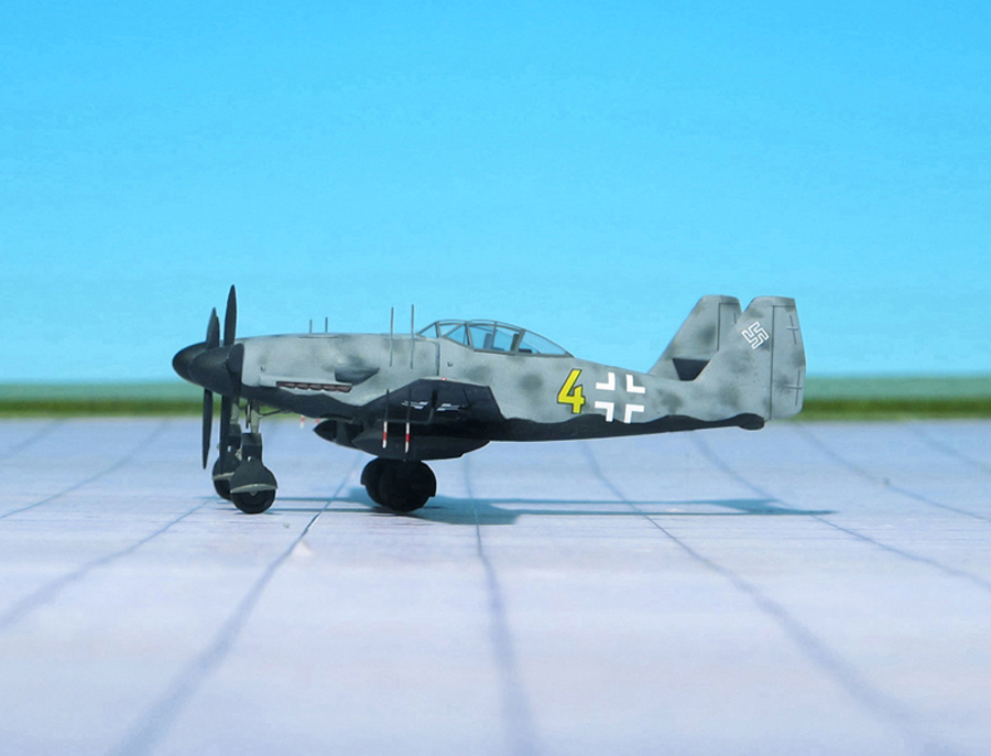
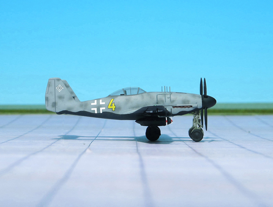
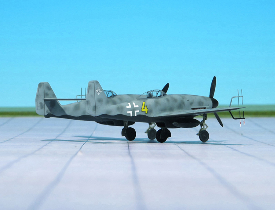
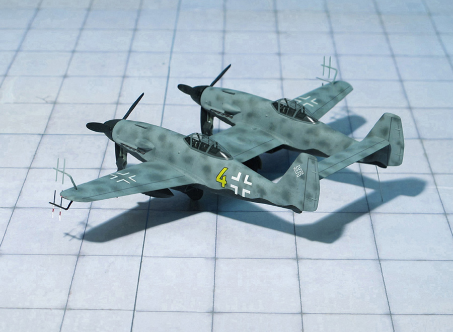
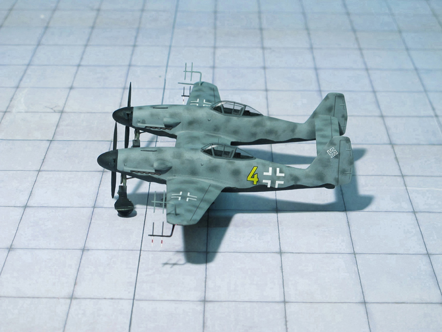
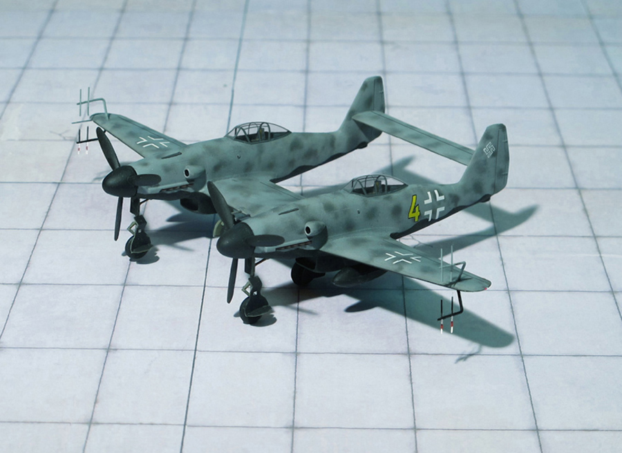
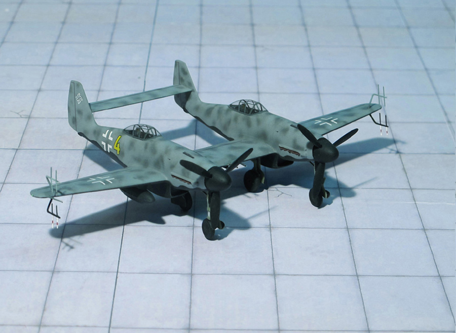
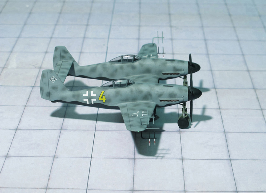
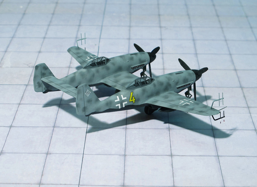
POWER PLANT: Two Daimler-Benz DB 603g liquid-cooled engines, rated at 1,726 hp each
PERFORMANCE: 472 mph at 27.800 ft
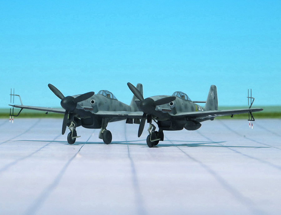
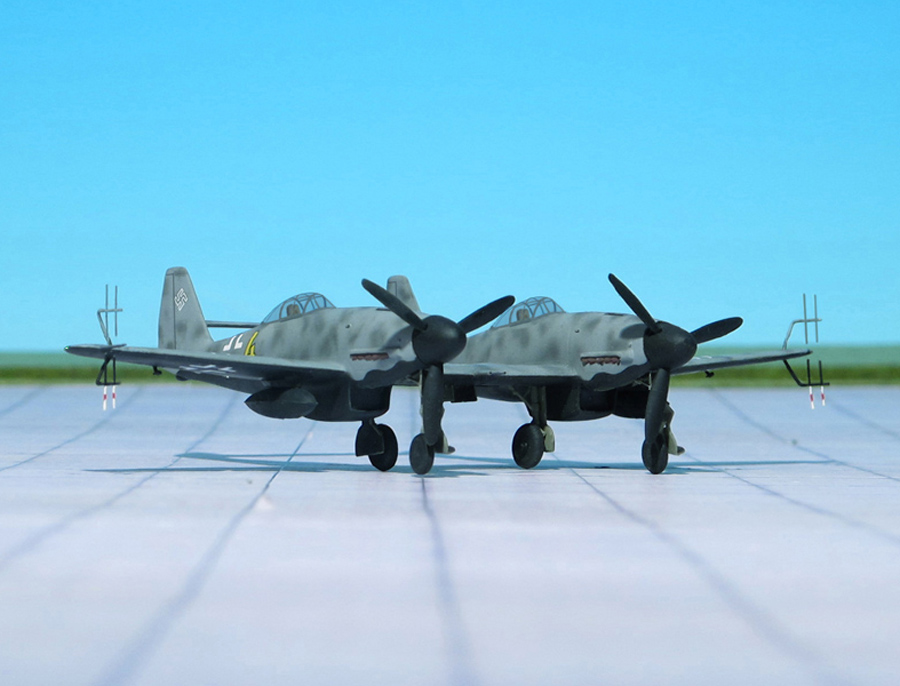
COMMENT: As early as 1940, the Messerschmitt design bureau concerned itself with the idea of fusing two fighters into a single airframe to provide a considerable increase in range and payload. The work was based on a RLM edict to simplify the number of combat aircraft to a few basic models.
Known as Messerschmitt Me 109Z Zwilling (twin) and Messerschmitt Me 609, the layouts were primarily intended as Zerstörer (Destroyer), Schnellbomber (Fast bomber or Nachtjäger (Night fighter). Following detailed examinations, the most suitable solution capable of early production indicated the use of a Daimler-Benz DB 605A-powered Messerschmitt Me 109G. A considerable performance increase, however, was to be expected if 2,000 hp Junker Jumo 213 engines were installed, requiring only a few alteration to incorporate complete major components of the standard aircraft. The modifications were limited mainly to the need of a completely new constant –cord wing center section and tailplane that simplified manufacture. Besides relocation of the undercarriage attachment points and the use of larger wheels, the ailerons and outboard leading-edge slots were lengthened and auxiliary fuel tanks were installed. In the course of development work on the twin aircraft, the Messerschmitt Me 309 was also considered and resulted in the Messerschmitt Me 609 destroyer, fast bomber and night fighter. The more powerful engine intended for the Messerschmitt Me 609 led to improvements in flight performance.
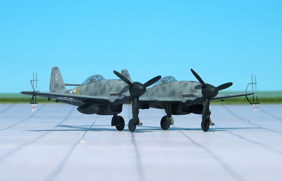
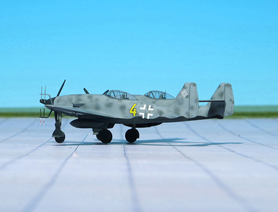
For the Night fighter version a FuG 217V/R “Neptun” radar with smal “Hirschgeweih” (Stag’s Antlers) aerial array was provided. These were mounted at the wingtips close to the leading edge. When all work on the unsuccessful Messerschmitt Me 309 was stopped all further effort on the Me 609 was cancelled (Ref.: 24).
Messerschmitt Me 609 NJ (Nachtjäger, Night fighter)
Messerschmitt Me 609 NJ (Nachtjäger, Night fighter)
Messerschmitt Me 609 NJ (Nachtjäger, Night fighter)
Messerschmitt Me 609 NJ (Nachtjäger, Night fighter)
Messerschmitt Me 609 NJ (Nachtjäger, Night fighter)
Messerschmitt Me 609 NJ (Nachtjäger, Night fighter)
Messerschmitt Me 609 NJ (Nachtjäger, Night fighter)
Messerschmitt Me 609 NJ (Nachtjäger, Night fighter)
Messerschmitt Me 609 NJ (Nachtjäger, Night fighter)
Messerschmitt Me 609 NJ (Nachtjäger, Night fighter)
Messerschmitt Me 609 NJ (Nachtjäger, Night fighter)
Messerschmitt Me 609 NJ (Nachtjäger, Night fighter)
Scale 1:72 aircraft models of World War II
Mit der weiteren Nutzung unserer Webseite erklären Sie sich damit einverstanden, dass wir Cookies verwenden um Ihnen die Nutzerfreundlichkeit dieser Webseite zu verbessern. Weitere Informationen zum Datenschutz finden Sie in unserer Datenschutzerklärung.