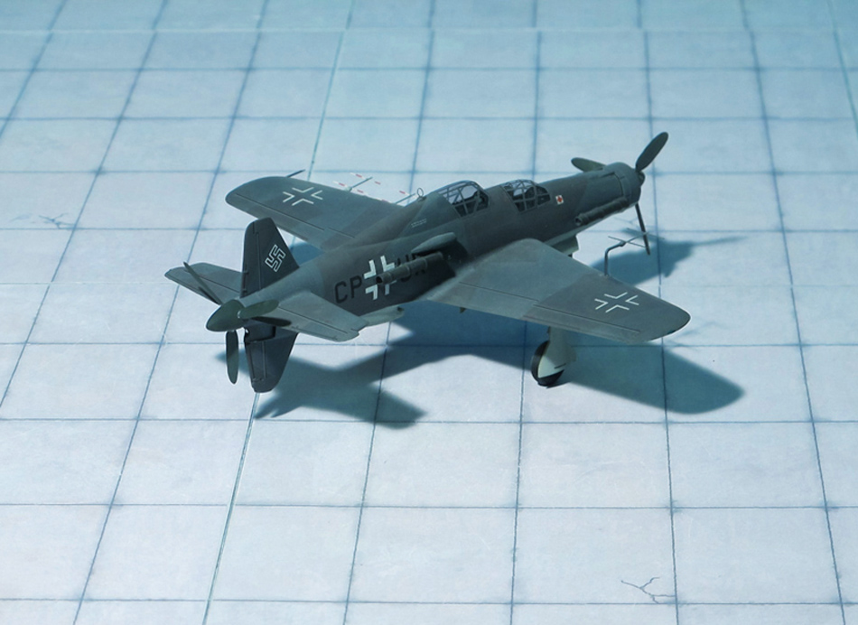
TYPE: Interceptor
ACCOMMODATION: Pilot only
POWER PLANT: One Heinkel/Hirth HeS 011 turbojet engine, rated at 1,200 kp thrust
PERFORMANCE: 480 mph at 32,800 ft
COMMENT: The Heinkel He P.1078 was a single-seat interceptor developed for the Luftwaffe by Heinkel aircraft manufacturing company under the „Jägernotprogramm“ (Emergency Fighter Programm) during the closing stage of the Third Reich.
Germany’s Emergency Fighter Program was enacted in the middle of July in 1944 in response to the Allied bombing offensive taking out critical German war-making capabilities. The new aircraft was intended to have superior performance in order to deal with the expected high altitude threats such as the Boeing B-29 Superfortress, but only had a 30-minute endurance figure.
The high-altitude fighter designs brought forward by other German aircraft makers were the Messerschmitt Me P.1101, Focke-Wulf Ta 183 „Huckebein“, Blohm & Voss Bv P.212, and Junkers EF 128.
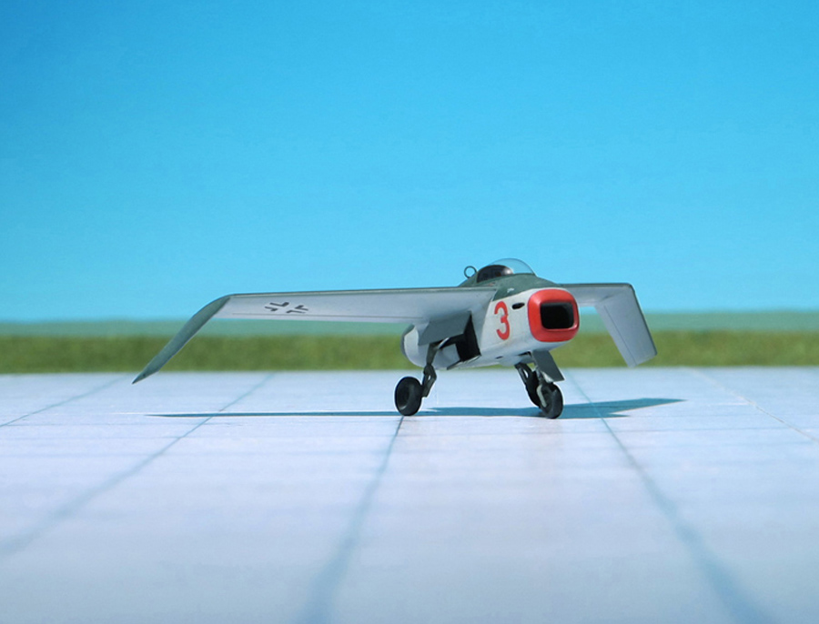
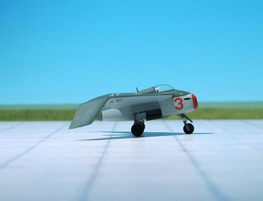
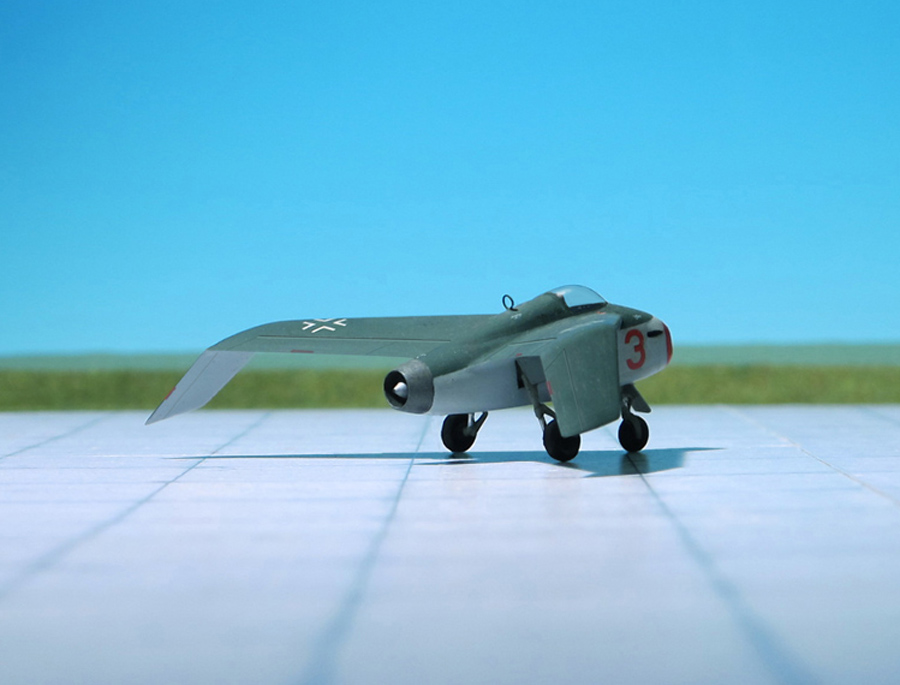
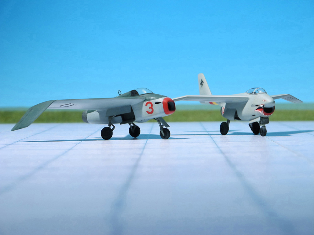
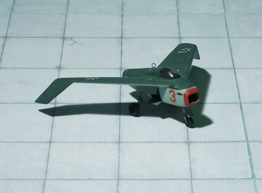
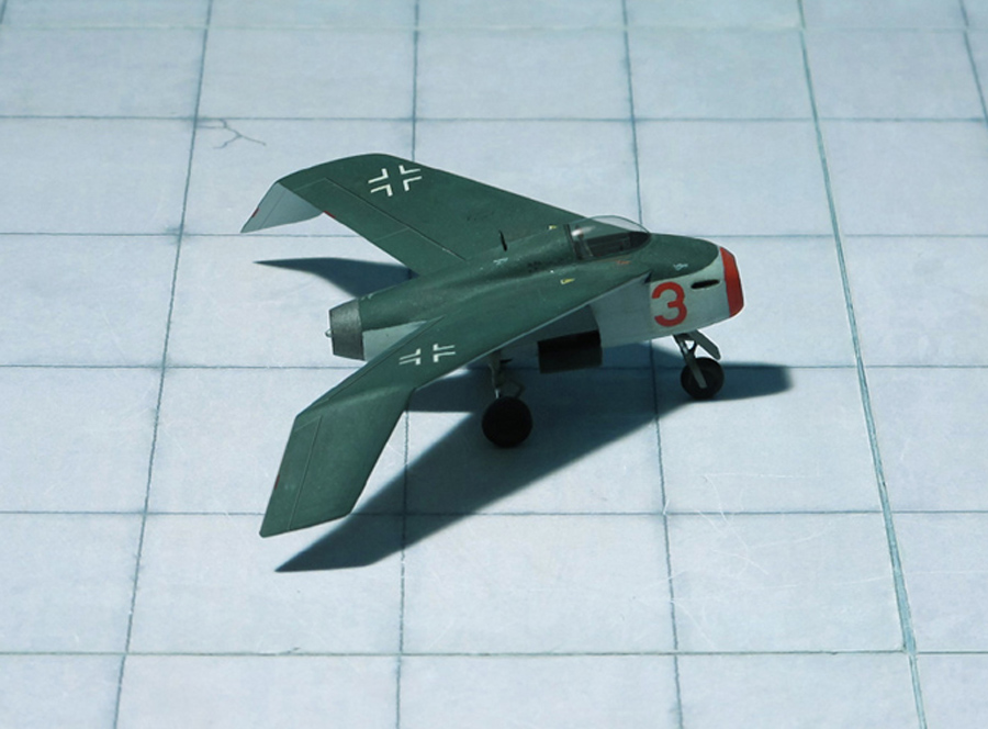
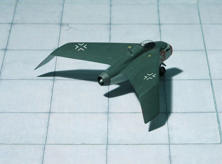
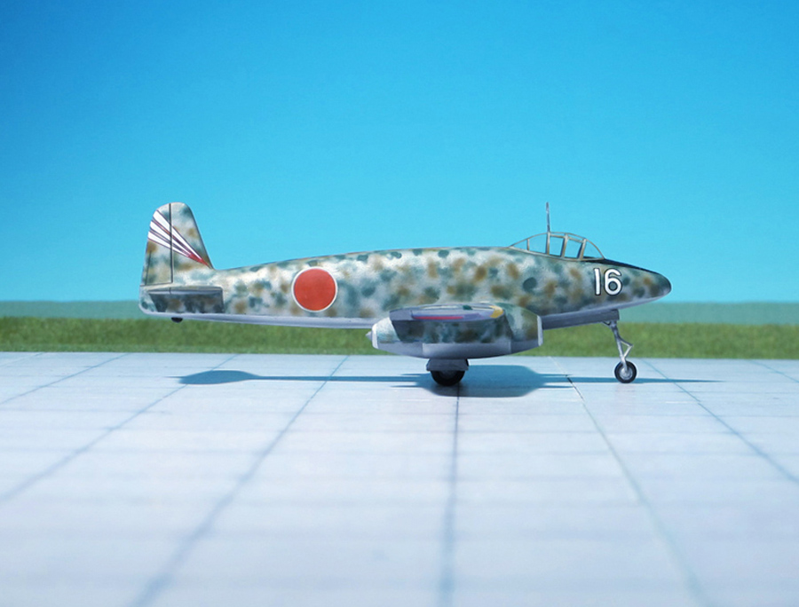
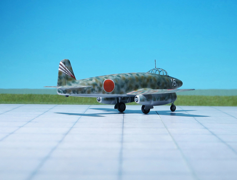
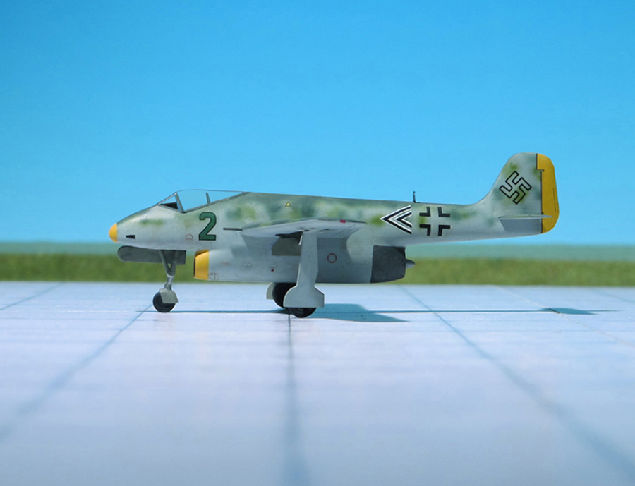
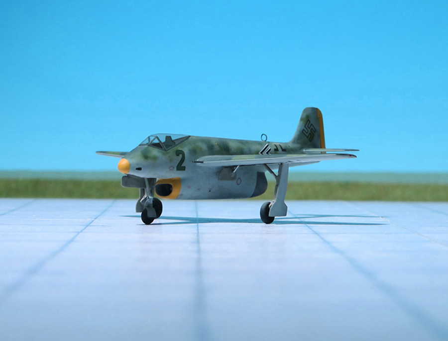
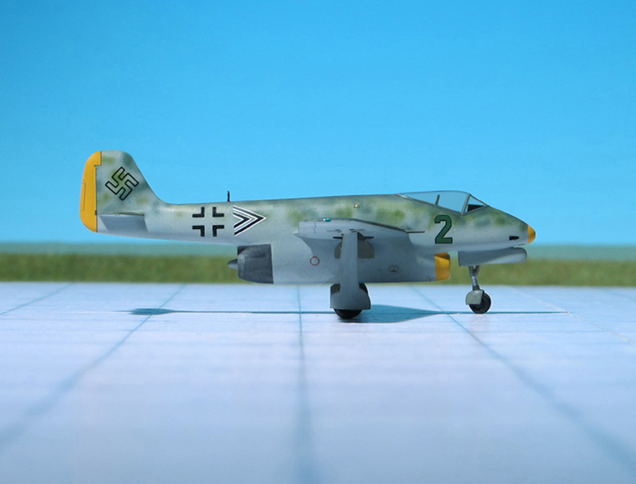
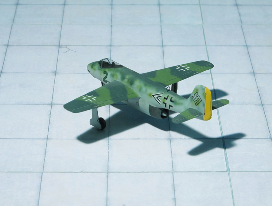
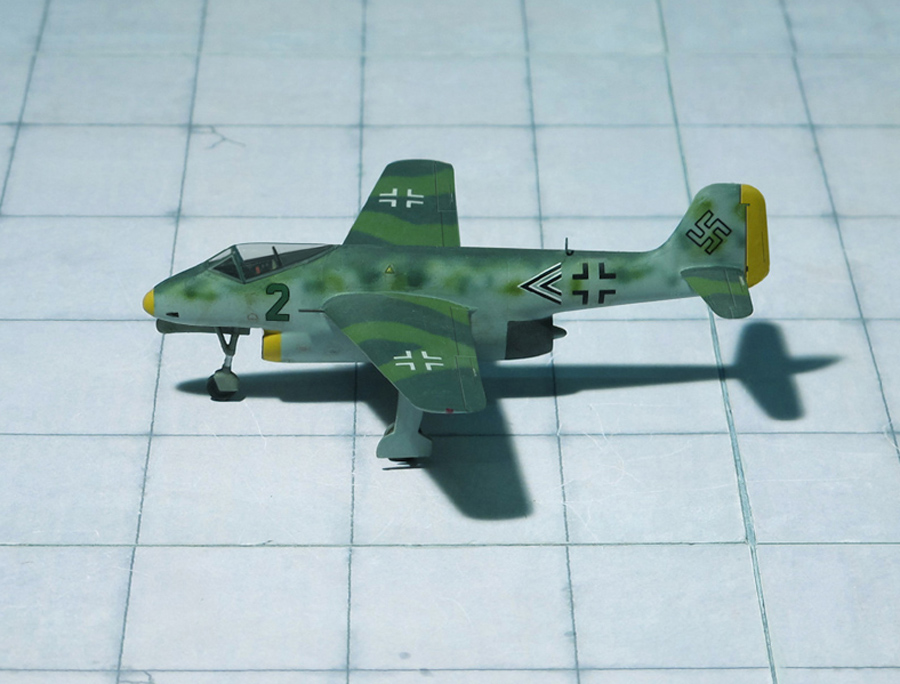
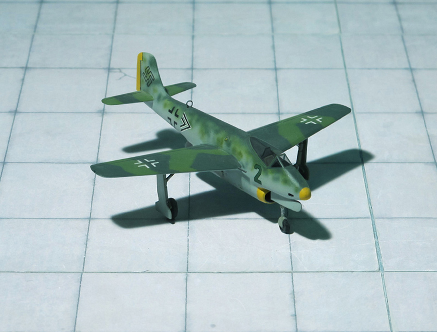
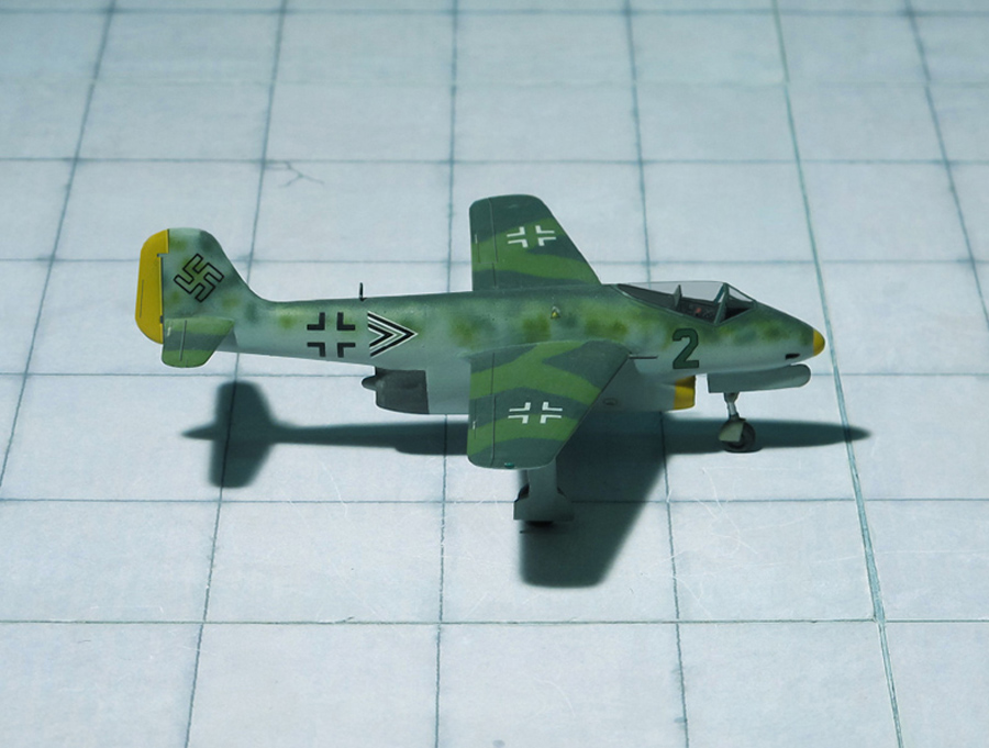
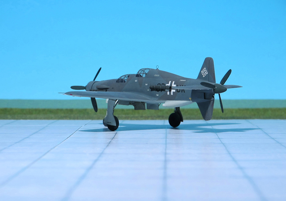
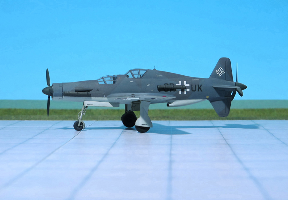
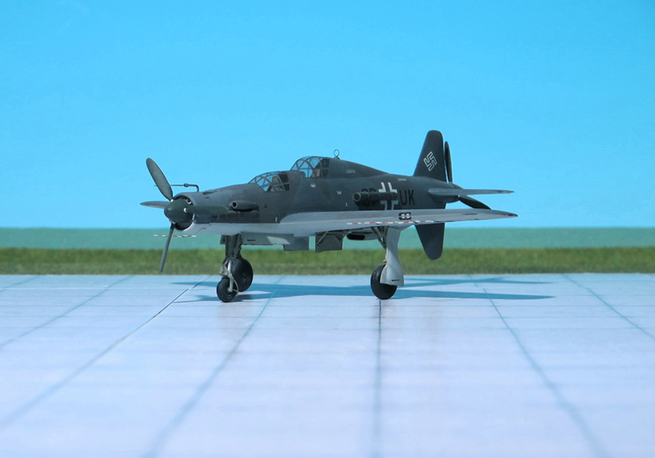
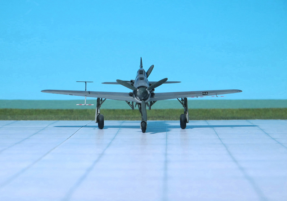
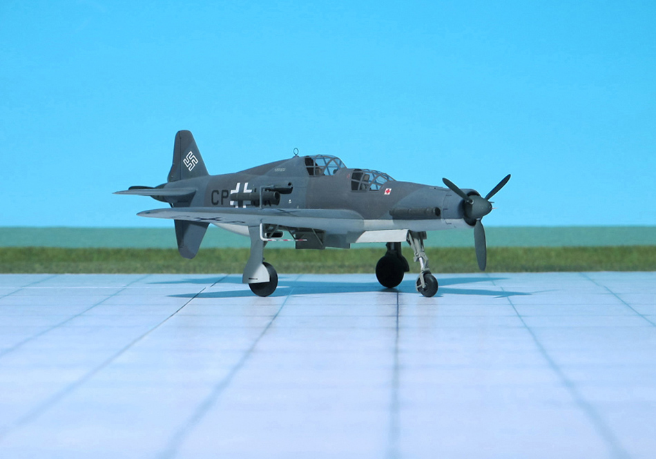
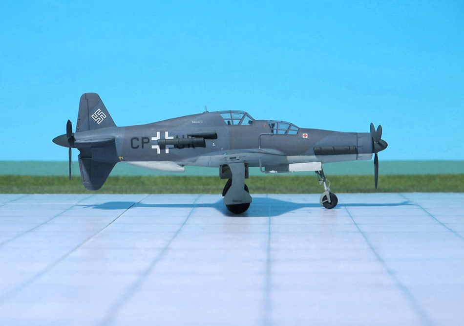
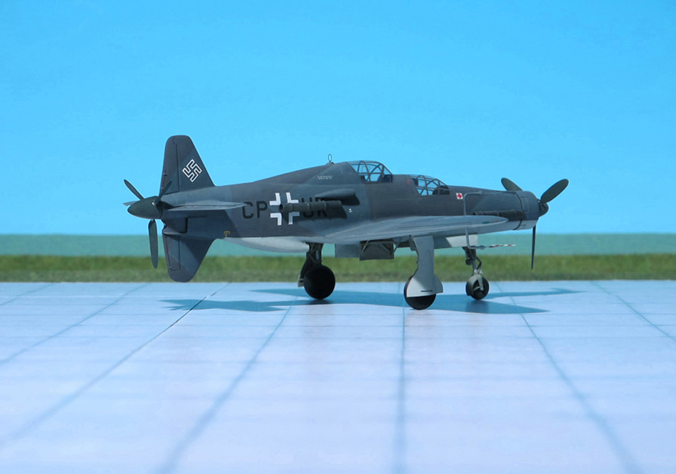
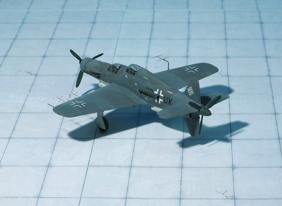
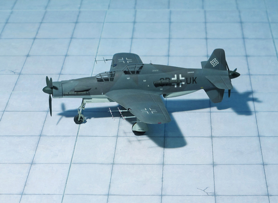
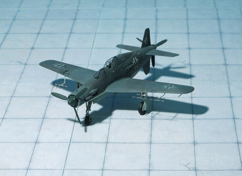
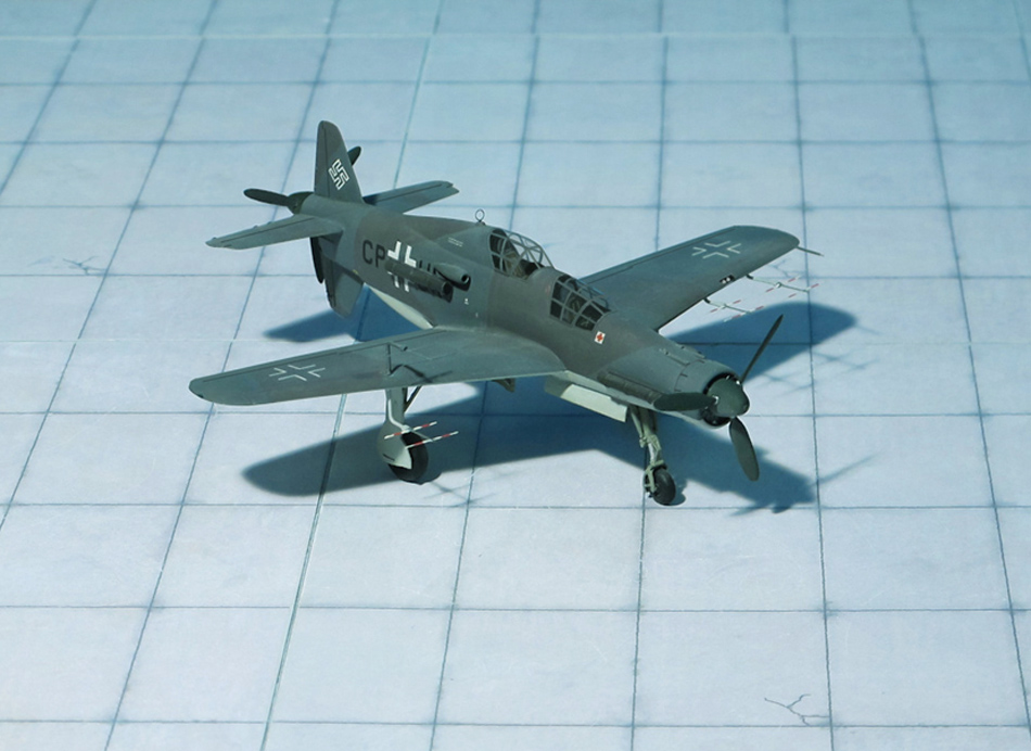
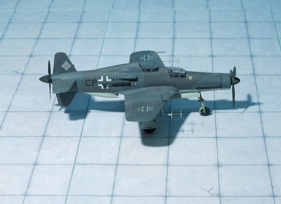
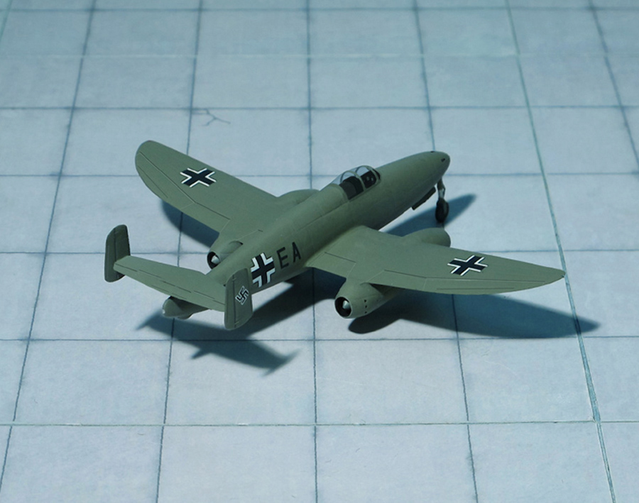
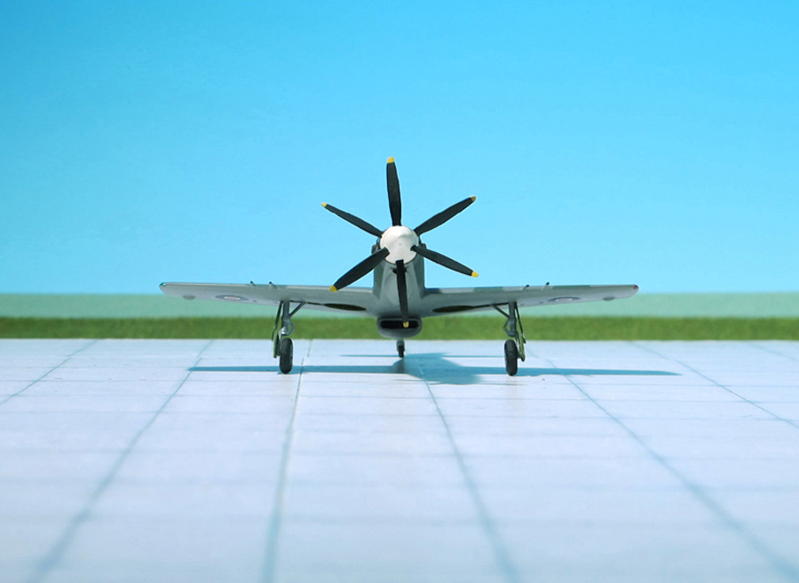
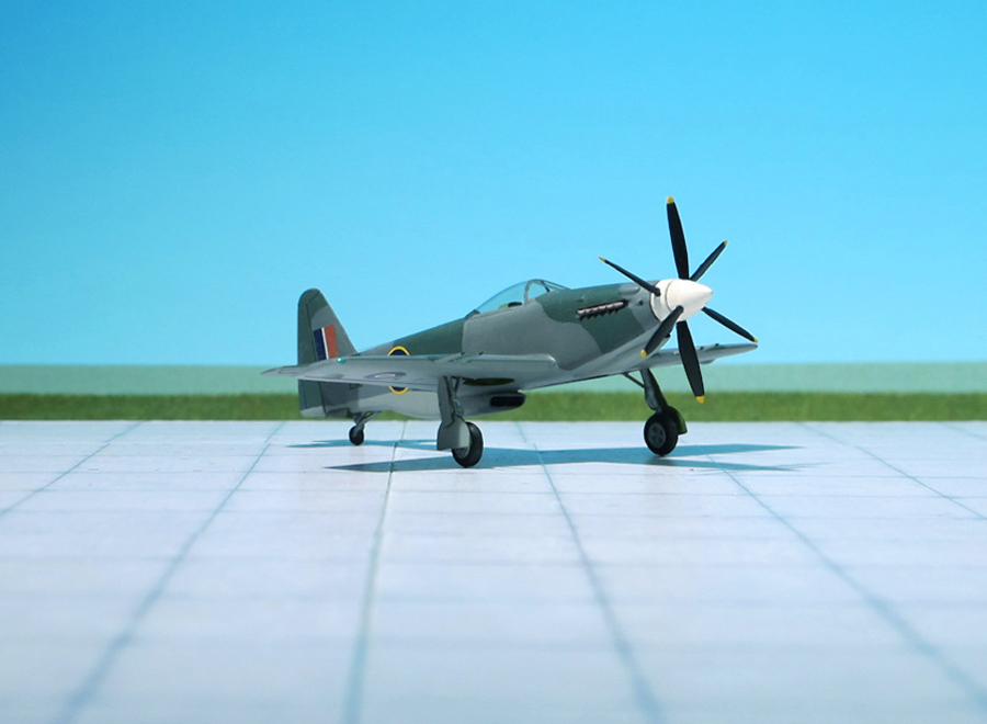
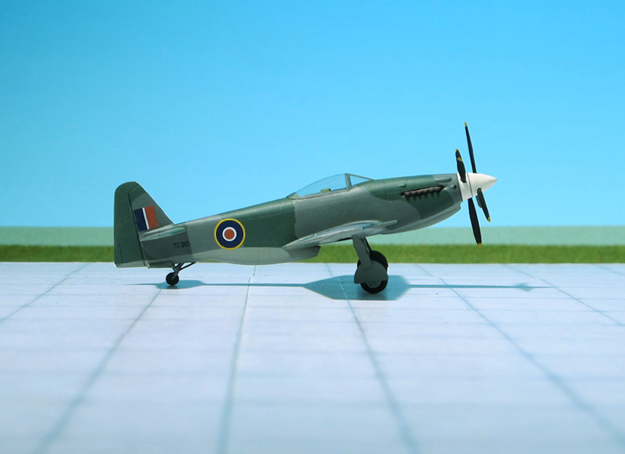
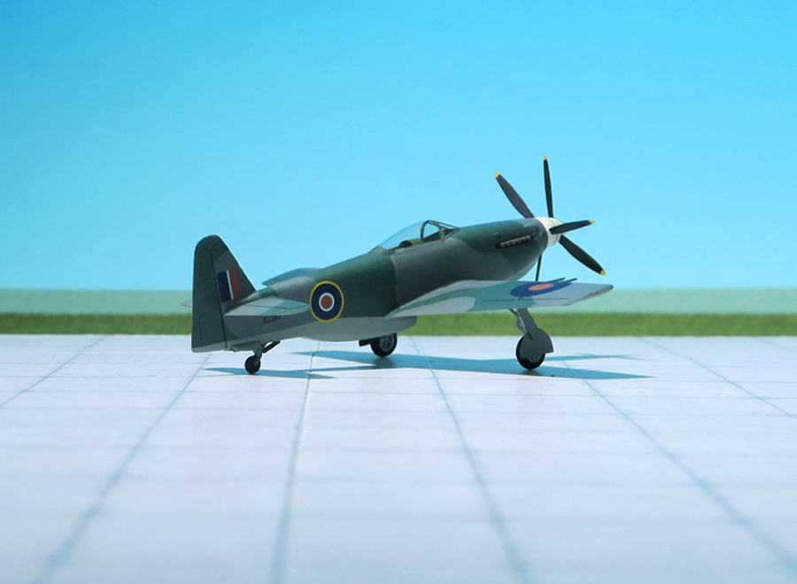
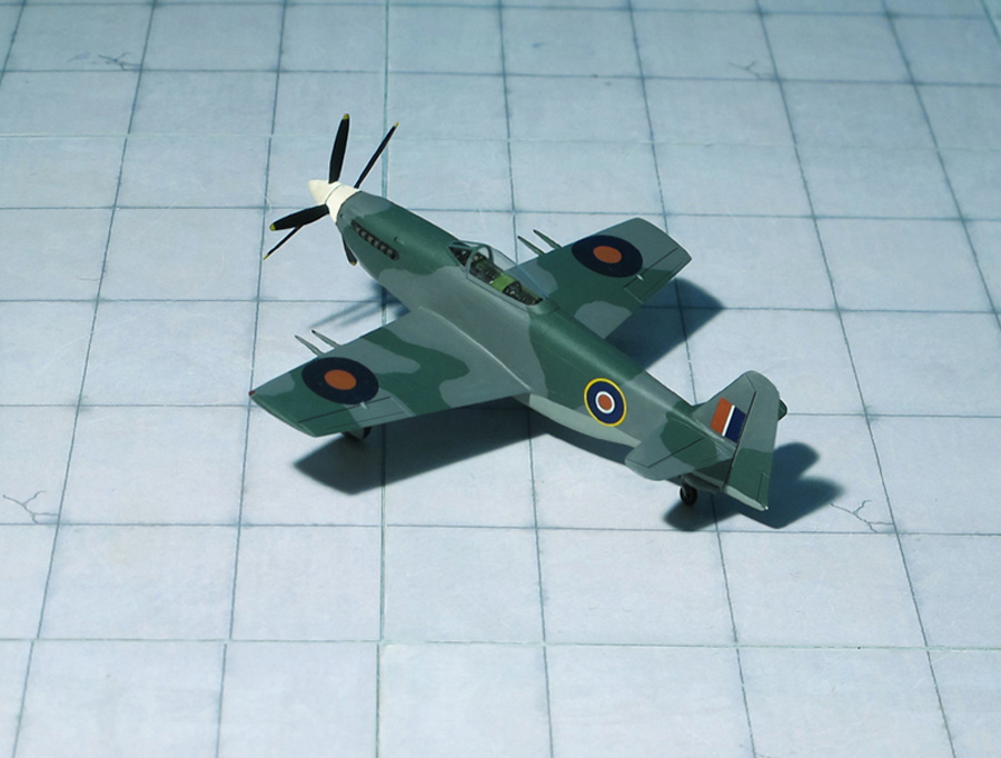
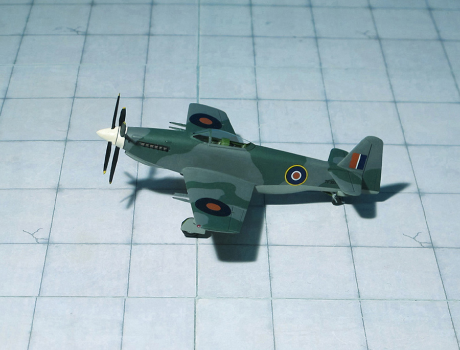
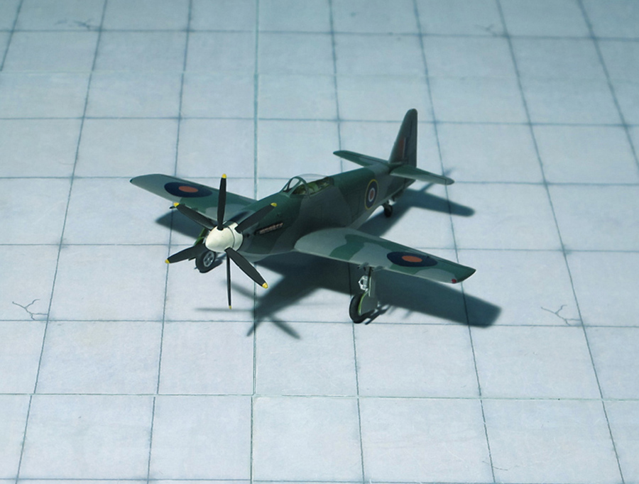
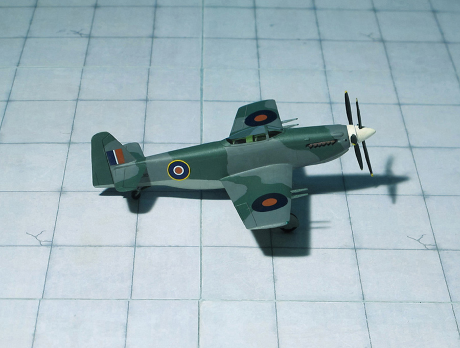
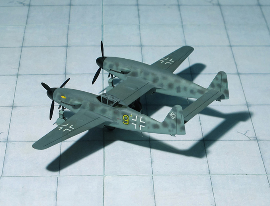
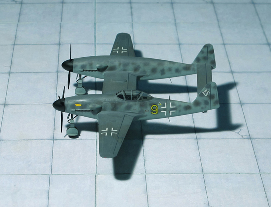
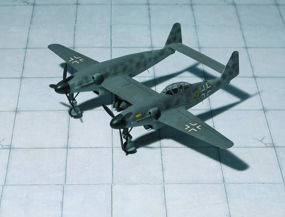
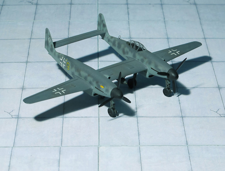
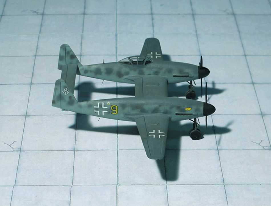
The Heinkel Company was a competitor, too, and offered ist He P.1078 project in three quite different variants. All of them were a single-seat fighters with polyhedral swept wings. The wings were swept back at 40 degrees and included wood in their construction. All of the projected aircraft had the wing tips angled downwards and all of them would be powered by a single Heinkel/Hirth HeS 011 turbojet.
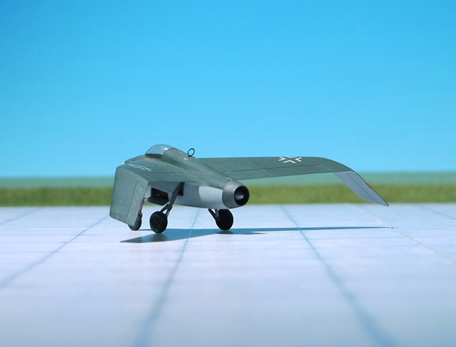
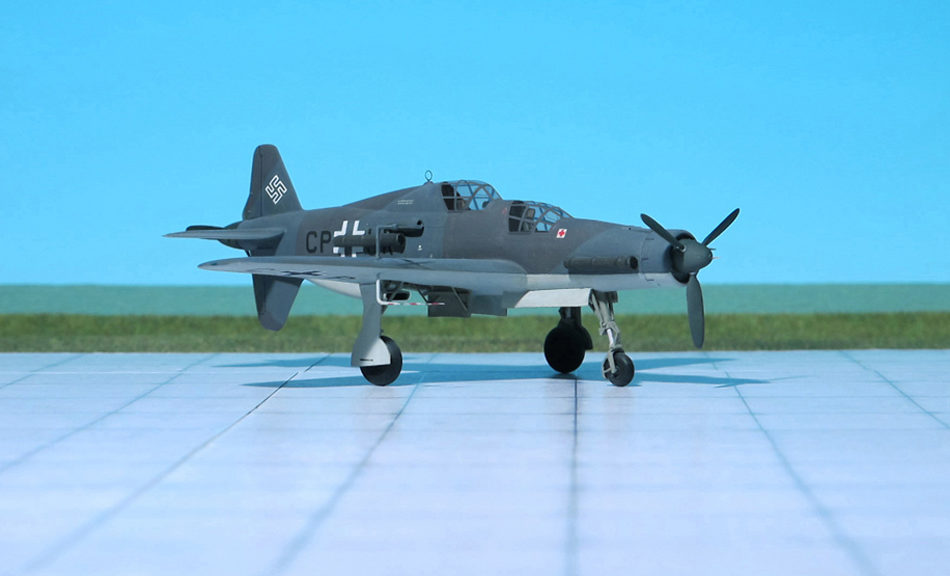
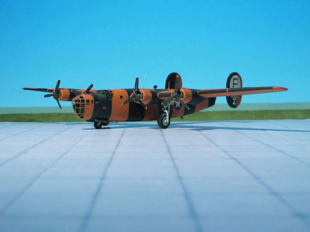
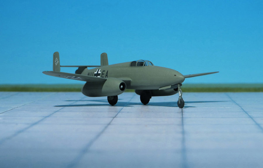
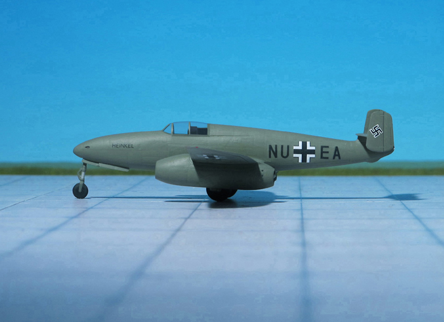
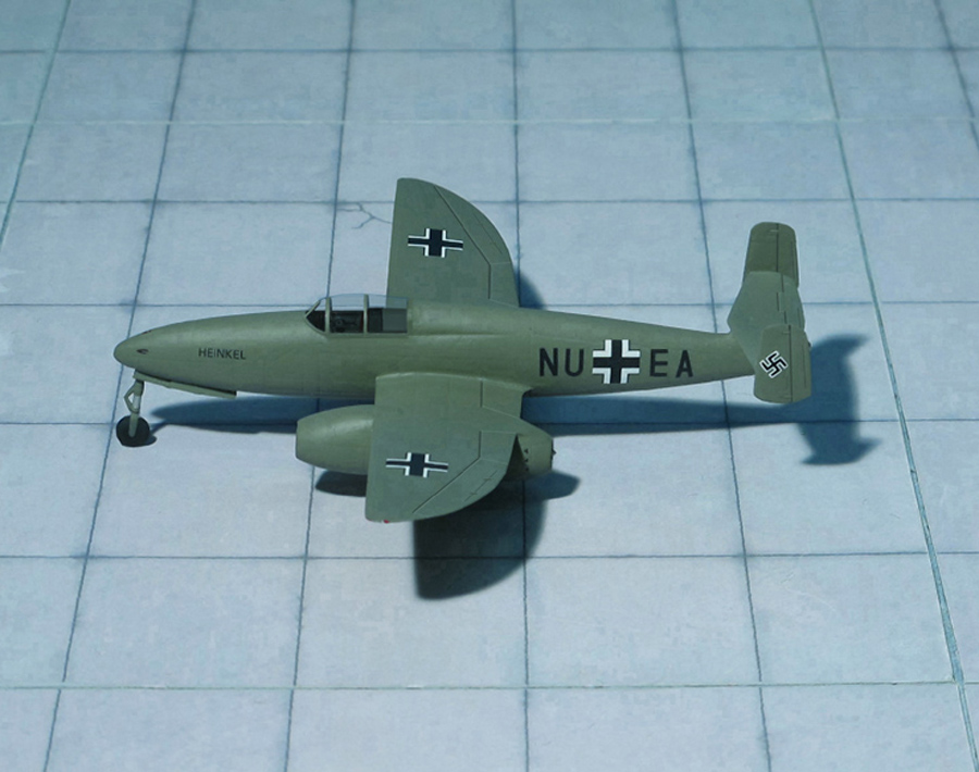
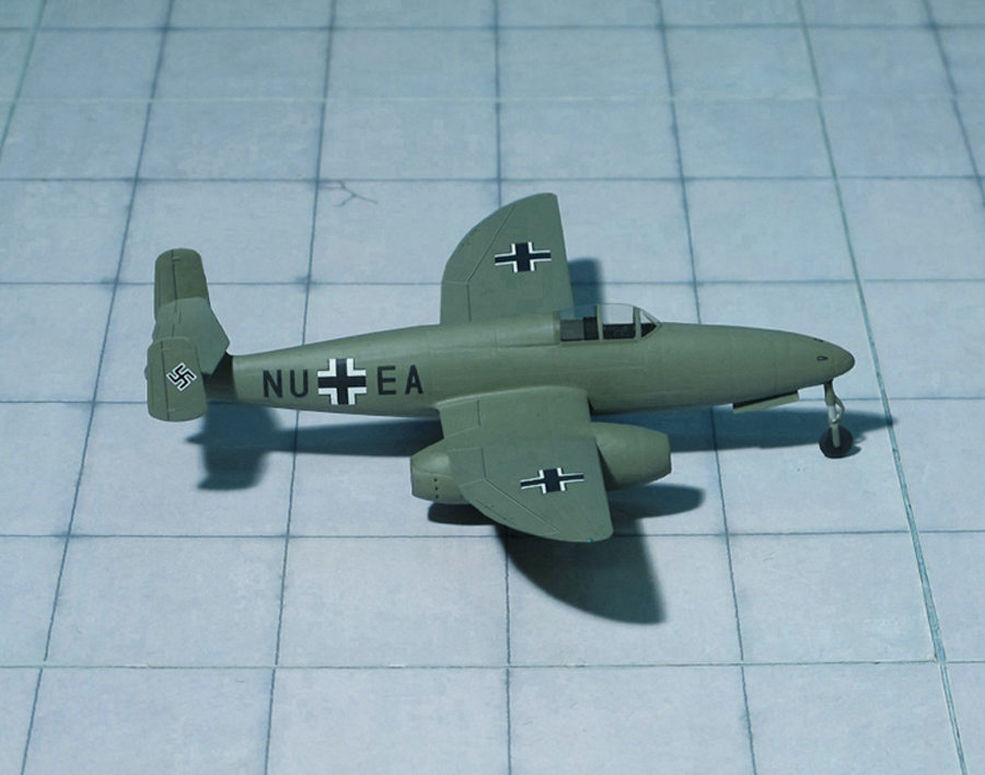
The Heinkel He P.1078A was a turbojet-powered interceptor. It was the most conventional-looking of the three designs submitted for it was the only one having a tail. Its armament was two MK 108 cannons, as in the following two variants.
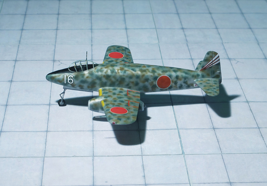
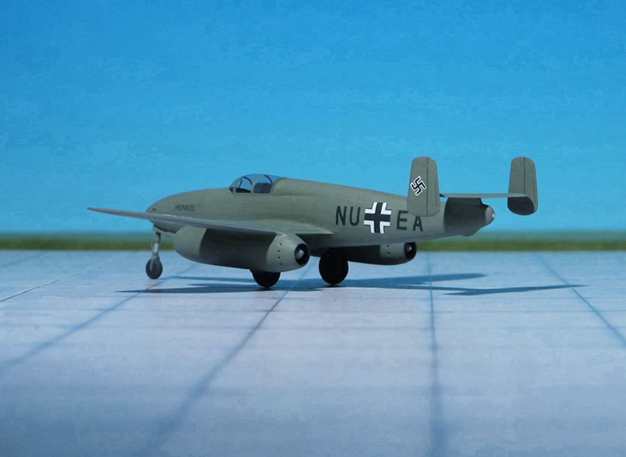
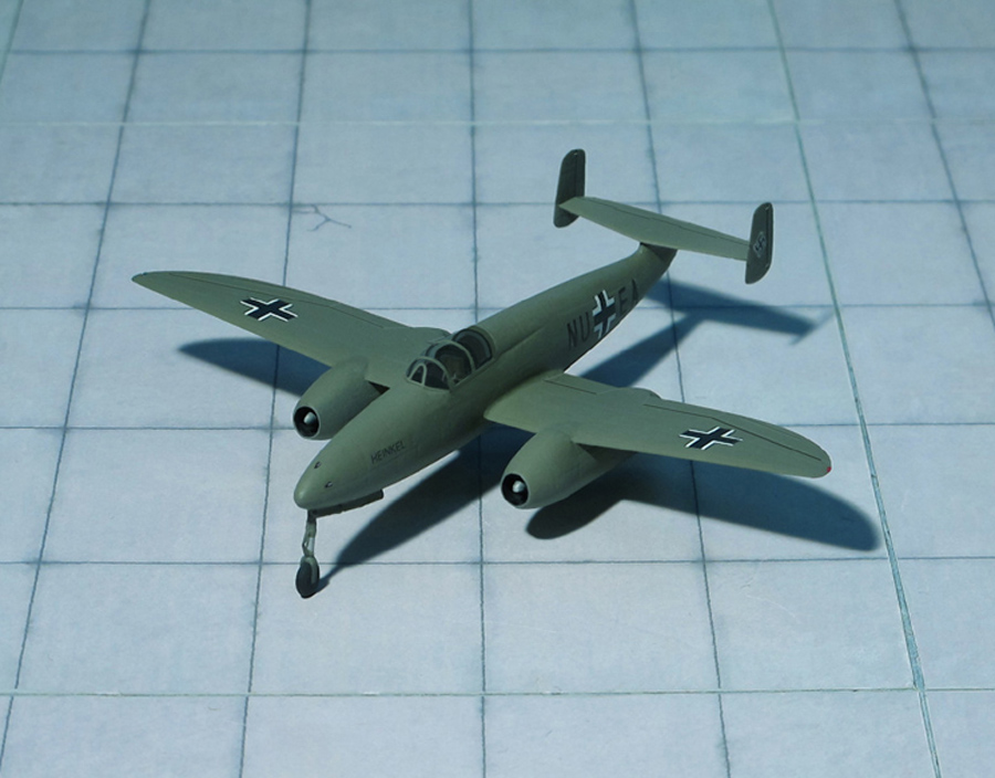
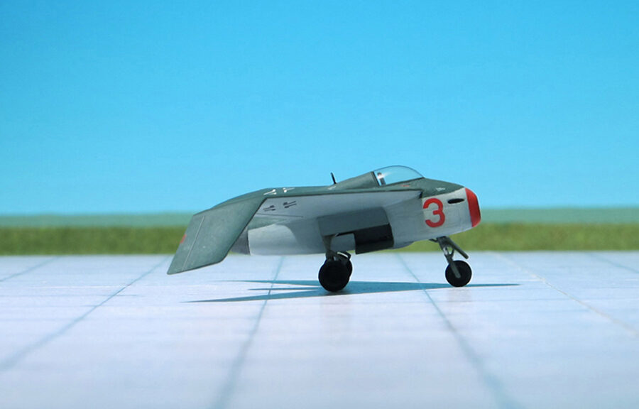
The Heinkel He P.1078B was a tailles asymmetric jet-powered interceptor with a short fuselage in which the air intake of the engine was located in the middle between two gondolas. The cockpit was located on the gondola of the left side, while the right side gondola contained the front undercarriage leg and cannon armament.
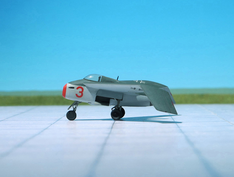
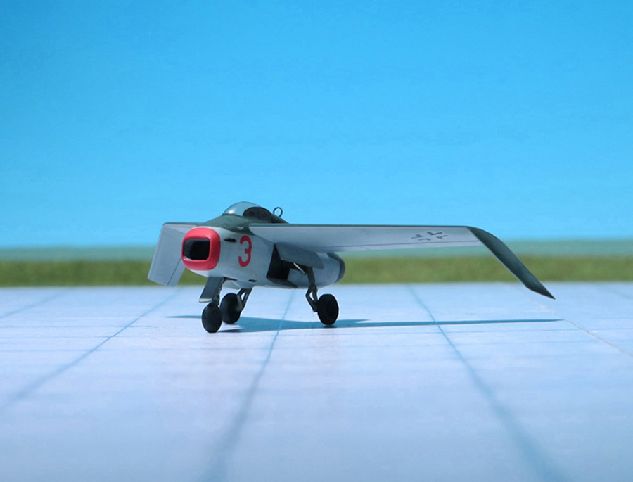
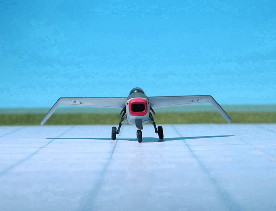
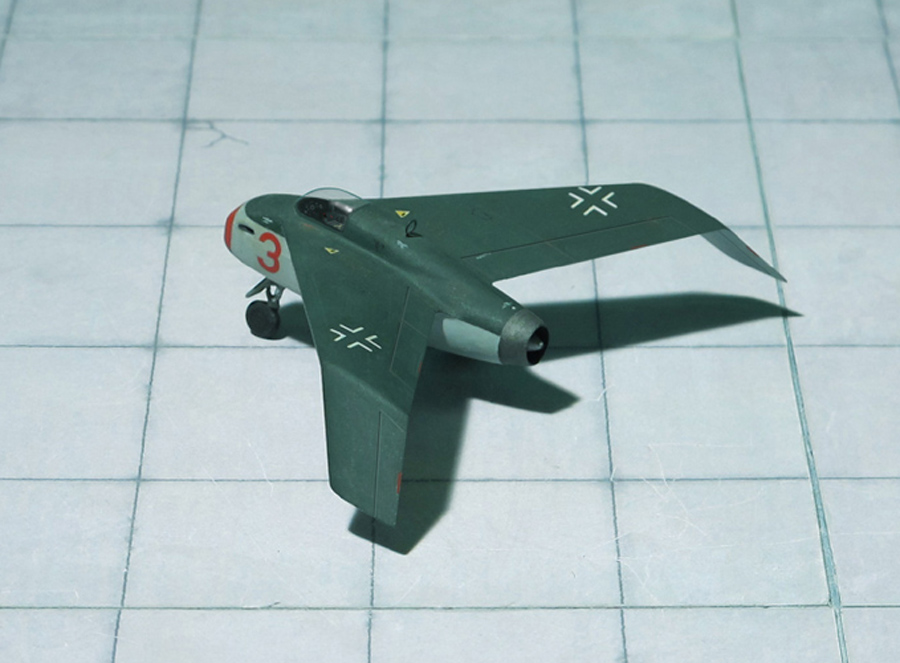
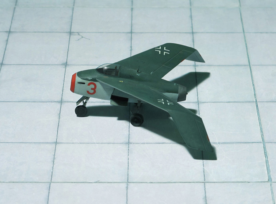
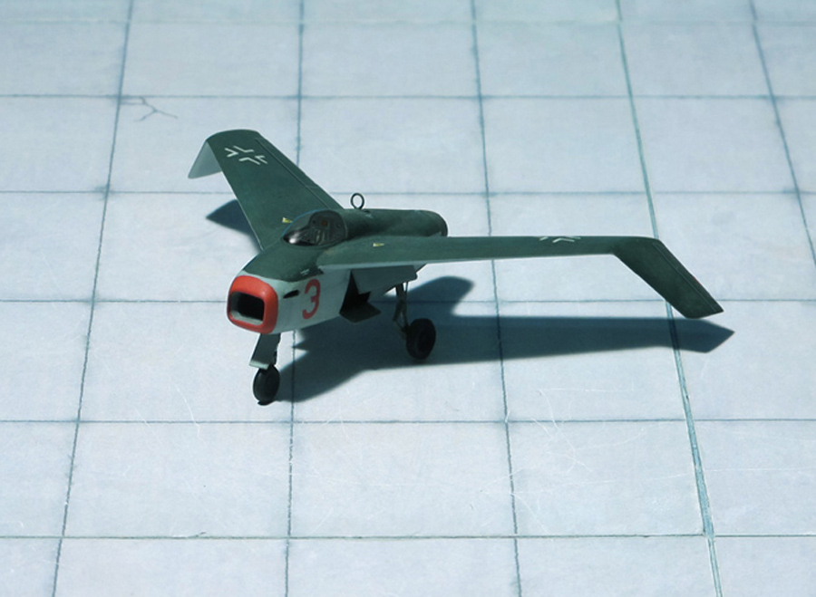
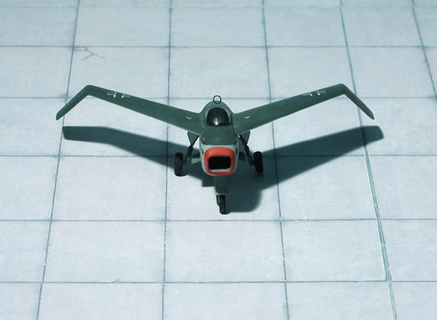
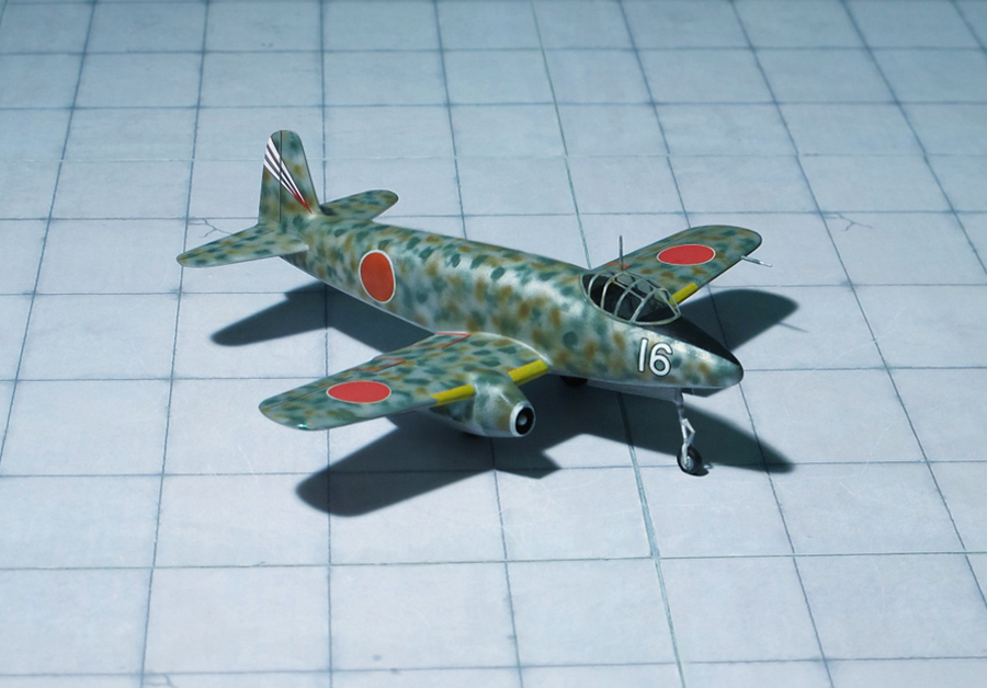
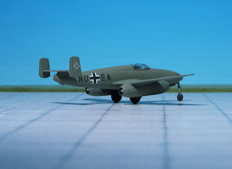
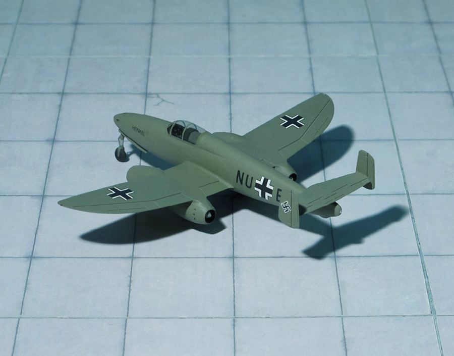
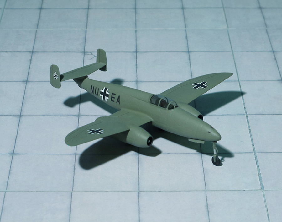
Finally the Heinkel He P.1078C was a tailless interceptor project similar to the He P.1078B but with a single short fuselage. Both the He P.1078B and He P.1078C had wing tips angled downwards at a more pronounced angle than the He P.1078A.
To keep production costs down and expedite mass production, the Heinkel He P.1078C design was relatively simple in nature, utilizing wood wherever possible. The metal fuselage sported a length no longer than 17 feet and contained the armored cockpit, armament and relatively large single engine fitting, fuel was to be housed in the wings. Wingspan was just under 30 feet and the design as a whole just topped 7 feet, 8 inches in height. The armament would have consisted of two MK 108 cannons fitted to either side of the nose section. The nose section itself was rather short and acted as the air intake to aspirate the turbojet engine buried further aft in the design. The opening was rectangular in nature and conformed well to the fuselage’s square appearance when viewed in the forward profile. The engine exhausted at the rear through a conventional exhaust ring. The cockpit was held well-forward in the design with the pilot seated under a small canopy allowing for limited viewing ahead and to the sides (the rear was obstructed by way of a short fuselage spine). The undercarriage was fully retractable and would have consisted of three landing gear legs: two main legs at amidships and a nose landing gear leg – all were single-wheeled installations. When at rest, this arrangement would have given the He P.0178C a distinct “nose-up” appearance, in effect perhaps promoting quicker take-offs with the increased wing drag at speed. Since the turbojet-powered fighter would have been operating at high altitudes, the cockpit was to be fully pressurized and equipped withan ejection seat.
Perhaps the most identifiable portion of the He P.1078Cs design was its wings. The assemblies were fitted high against the fuselage sides and extensively swept rearwards. Each wing was cranked upwards from fuselage centerline up to roughly three-quarters out and then capped with a short wing piece cranked sharply downwards. The reason for this design was largely related to aerodynamic principles that were still being researched at the time and the result was to have combated stress effects on the wings at high speeds. Ernst Heinkel was convinced of their ability to provide for increased maneuvering and agility during dogfights. It bears note that there were no horizontal tailplanes in the Heinkel design and the entire internal fuel load for the thirsty turbojet engine was to be stored across both of the wings. However, the wings were not armored which unduly would have exposed them to enemy fire even of the slightest degree.
After being subject to severe criticism, the project was cancelled by Heinkel at the end of February 1945 (Ref: 17, 22, 24).