POWER PLANT: One Armstrong Siddeley Genet Major IA radial engine, rated at 140 hp
PERFORMANCE: 110 mph
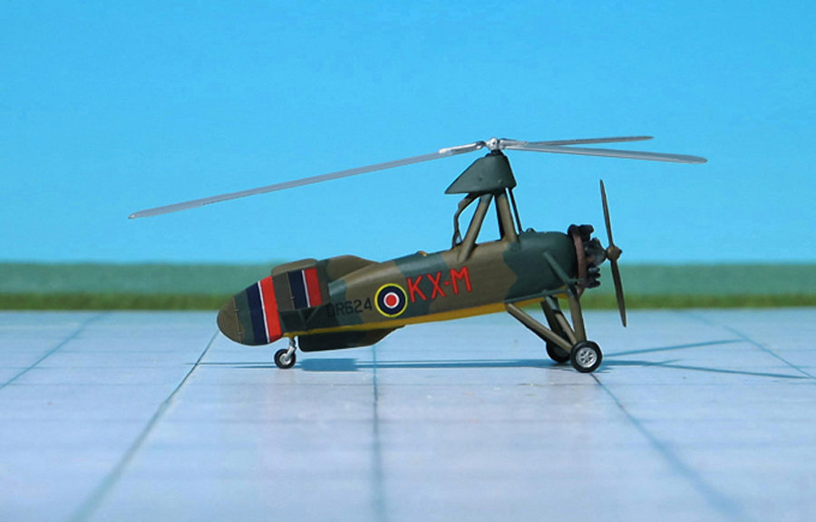
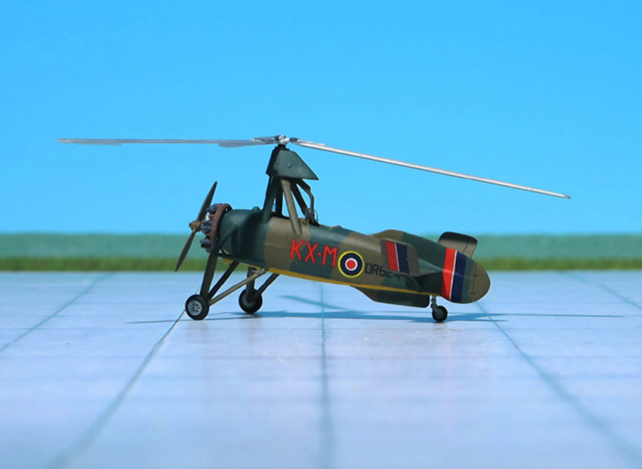
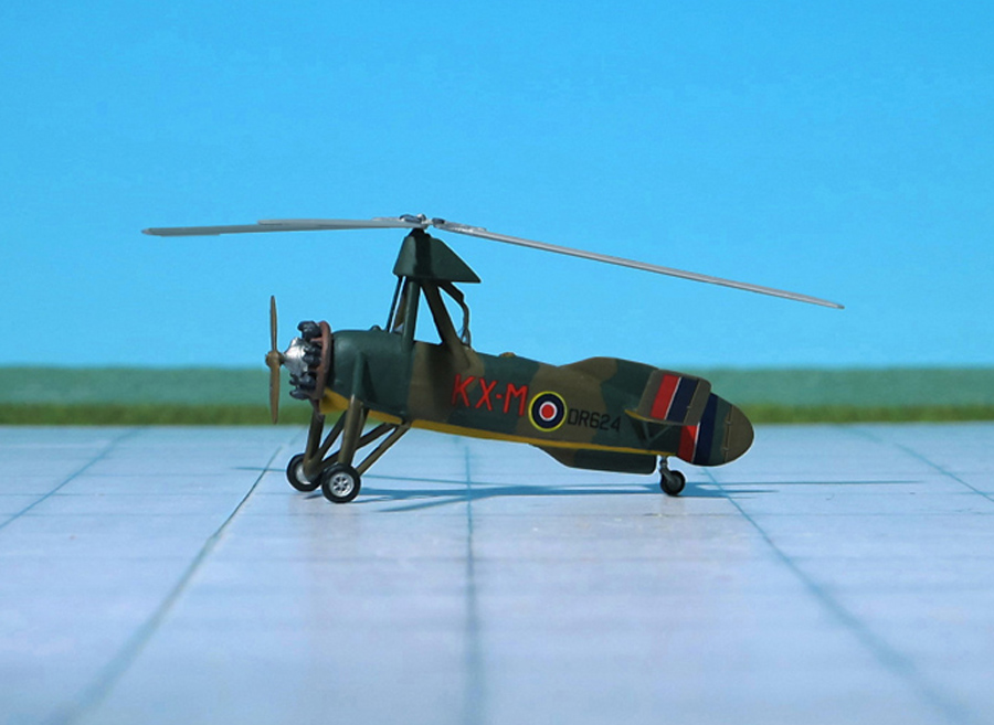
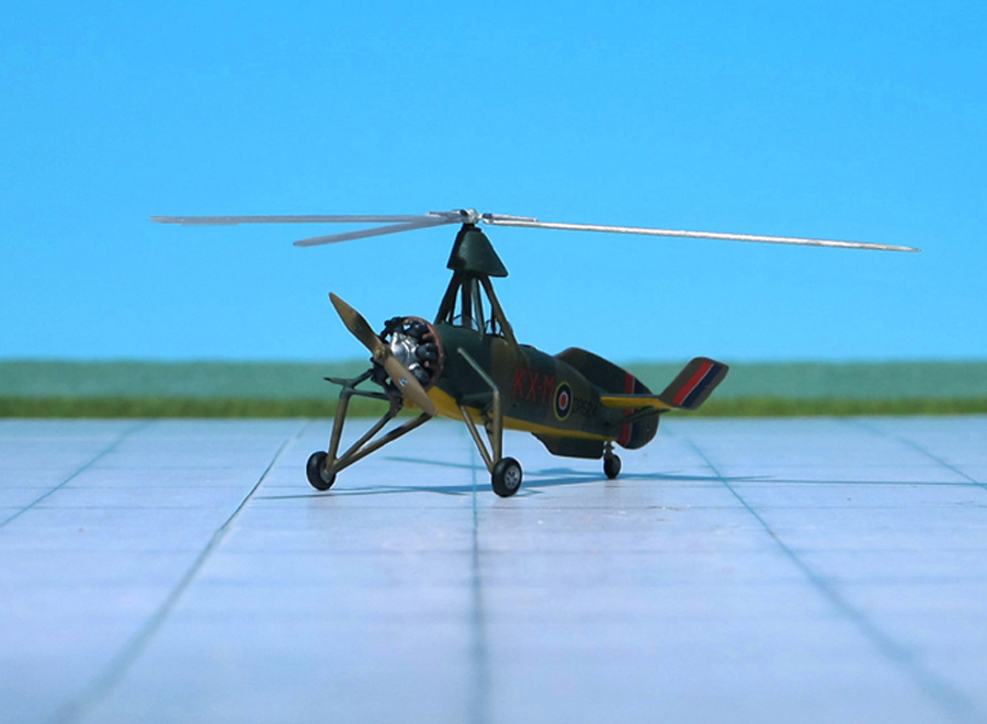
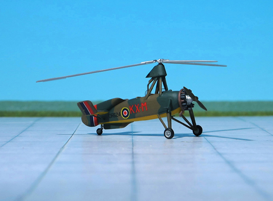
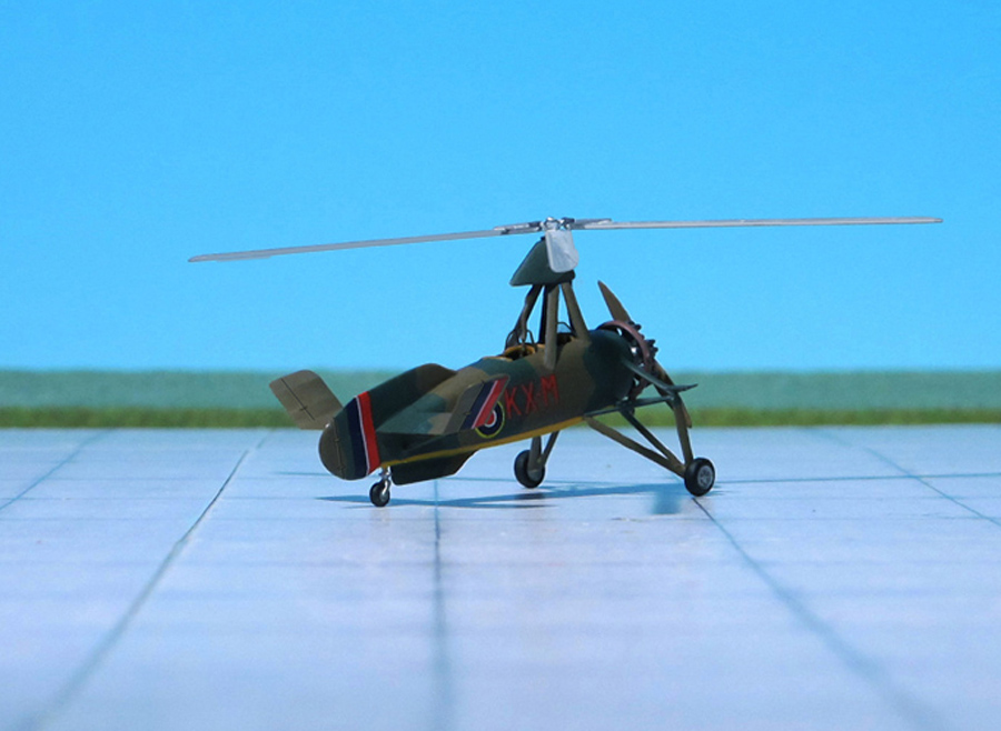
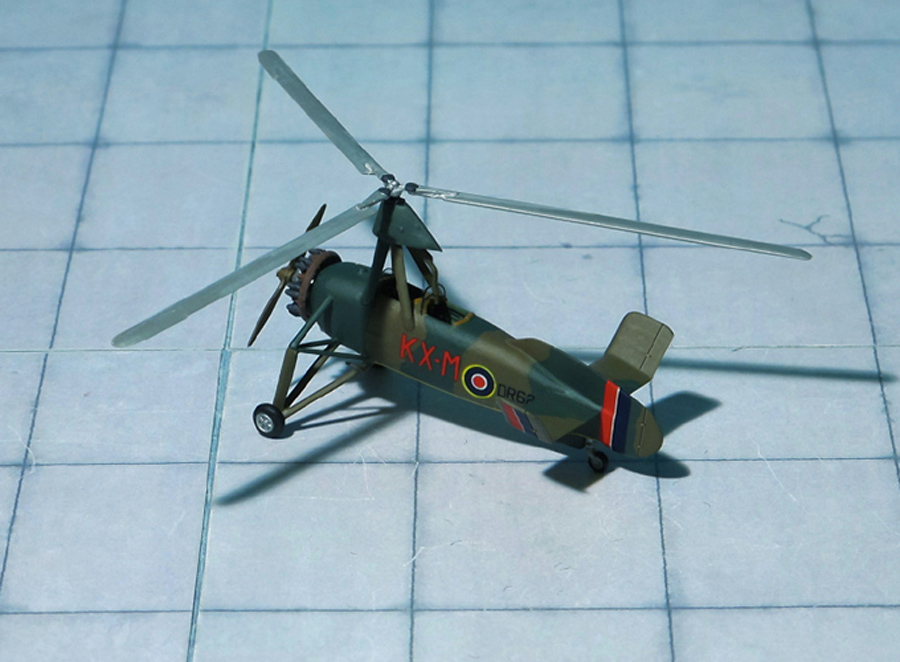
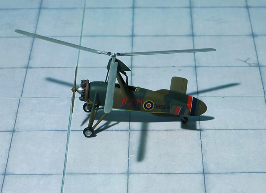
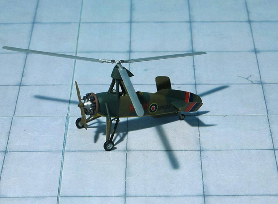
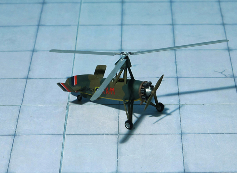
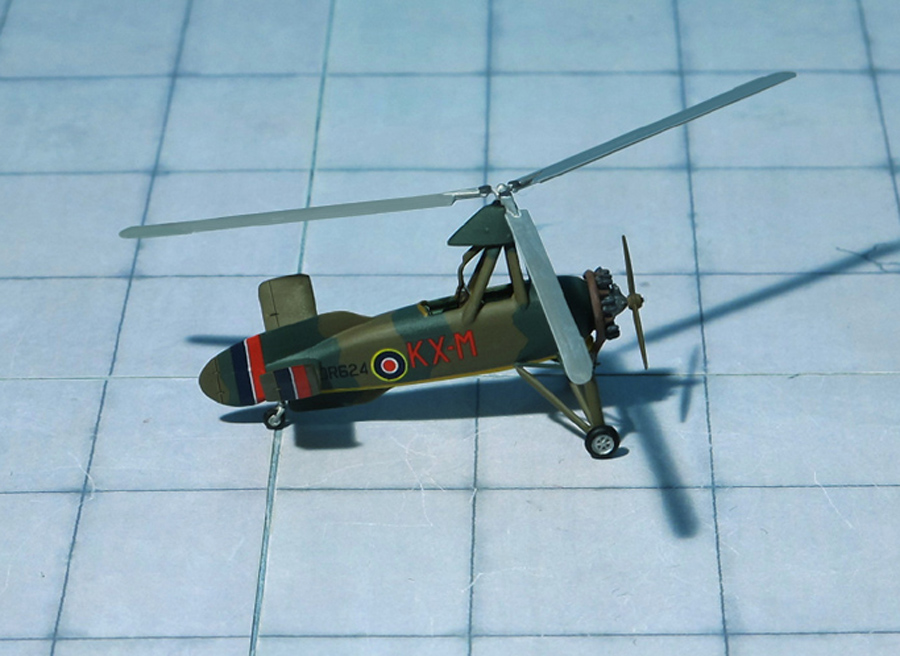
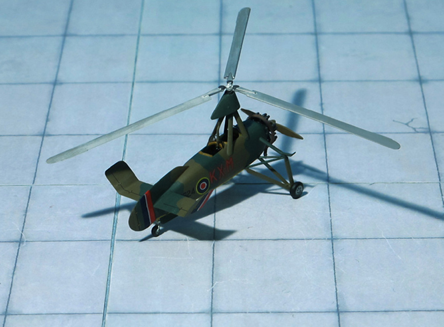
COMMENT: The Avro 671 Rota Mk. I autogyro based on the Cierva C.30 designed by Juan de la Cierva in Spain and built under licence in England by A V Roe & Co Ltd.
Avro obtained the licence in 1934 and subsequently built 78 examples under their model designation, fitted with an Armstrong Siddely Genet Major IA (known in the RAF as the Civet 1) 7-cylinder radial engine producing 140 hp . The first production aircraft was delivered in July 1934.
The first production design in the series was the C.30A, a radial-engined autogyro with a three-blade, 37 ft rotor mounted on an aft-leaning tripod, the control column extending into the rear of the two cockpits. The engine was the five-cylinder, 105 hp Armstrong Siddely Genet Major I. The fabric-covered fuselage carried an unbraced tail plane, without elevators but with turned-up tips. The port side of the tail plane had an inverted aerofoil section to counter roll-axis torque produced by the propeller. As with most autogyros, a high vertical tail was precluded by the sagging resting rotor, so the dorsal fin was long and low, extending well aft of the tail plane like a fixed rudder and augmented by a ventral fin. The wide-track undercarriage had a pair of single, wire-braced legs and a small tail wheel was fitted. This model flew in April 1933. It was followed by four improved machines designated C.30P (P here for pre-production) which differed in having a four-legged pyramid rotor mounting and a reinforced undercarriage with three struts per side. The rotor could be folded rearwards for transport. The C.30P used the more powerful140 hp Armstrong Siddely Genet Major IA radial engine.
Twelve C.30A’s built by Avro for the Royal Air Force (RAF) entered service as the Avro 671 Rota Mk.I. The twelve were delivered between 1934 and 1935. They equipped the School of Army Co-operation at RAF Old Sarum near Salisbury. At least one RAF C.30A was on floats as a “Sea Rota” in January 1935
Many of the surviving civil aircraft were also taken into RAF service between 1939 and 1940. In 1940 they equipped 1448 Flt at RAF Duxford. Later they equipped 529 Sqn at RAF Halton on radar calibration work, disbanded in October 1945, the twelve survivors were sold on to civilian owners (Ref.: 24).
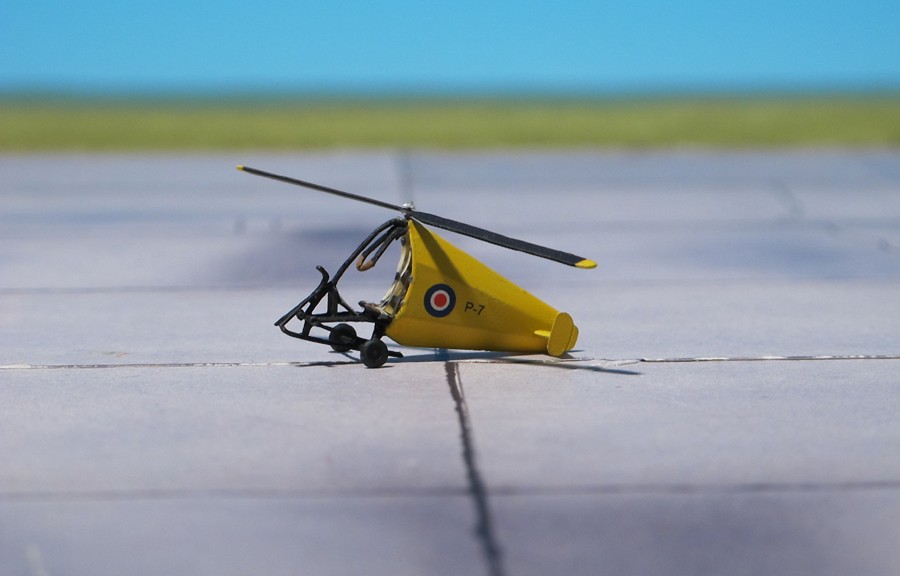
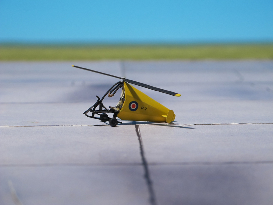
COMMENT: The Hafner H.8 Rotachute was a British 1940s experimental one-man rotor kite designed by Raoul Hafner, an Austrian engineer who specialized in rotary wing design, and who had moved to the UK in 1933 to continue his research and development work. In 1940, he proposed the use of a single-place strap-on rotor kite in place of a conventional parachute, to deliver a soldier accurately to a battlefield. The proposal was made to the Air Ministry in the light of a shortage of silk for parachute manufacture. Hafner was briefly interned as an alien, but was released to pursue the feasibility of the idea at the Central Landing Establishment (CLE) located at RAF Ringway. In October 1940, work began on design and construction of rotor systems and scale models of rotor kites. The first models were made of wood and fabric, ballasted to represent a pilot, and had a rotor span of about 3 ft. They were tested successfully by hand launching, but suffered buffeting and lack of autorotation when launched from aircraft at height. The third evolution, designated “M.3”, had metal rotor blades, and after further modifications made the first successful launch and descent from a De Havilland Tiger Moth. Further developments and tests continued into February 1941. The tenth evolution scale model (M.10) had mass-balanced wooden rotors, ballast of 45.3 kg, and a rotor span of 10 ft. On March 1941, the M.10 model was successfully air-launched from a Boulton & Paul Overstrand.
The design of the man-carrying machine known as a Rotachute, also known as a Hafner H.8, evolved from November 1940 and throughout 1941. In September 1941, the Central Landing Establishment was renamed the Airborne Forces Establishment. The Rotachute Mark I design initially comprised a tubular steel framework with a single seat, rubber-mounted rotor hub, hanging control column, skid undercarriage, and a self-inflating rear fairing made of rubberised fabric with integral tailplane. The two rotor blades, of wooden construction, could achieve flapping and coning characteristics via hinges on the rotor hub. Fixed footrests were provided, plus fittings below the seat to accommodate a soldier’s weapon, such as a Bren gun. The control column offered two-axis control, rolling and pitching, with turns made via controlled rolling movement. Air Ministry Specification No. 11/42 was issued retrospectively to describe the outline requirements. The Ministry of Aircraft Production sub-contracted construction of parts to specialist firms including F. Hills and Sons, Airwork General Trading, Dynaflex, Dunlop, and H. Morris & Co. Some full size rotor trials were carried out using a pivoting rig mounted on a Ford flatbed truck, and full-size unmanned airframes were used in ground-based and inflight trials.
In January 1942, trials of the Rotachute Mark I were conducted to assess the aerodynamic characteristics while mounted on the truck-mounted rig, with pilot control of the aircraft in forward motion. On 11 February 1942, the prototype Rotachute was first manually flown from a wheeled trolley while under tow behind a Humber car at Ringway, after starting the rotor by hand. On that and on a subsequent trial, the machine rolled over after landing, sustaining damage to the blades but not to the pilot. A tethered test beneath a barrage balloon and a longer test flight at RAF Snaith were both more successful. The flexible tail section evidently offered inadequate directional stability, and the consequence was the Rotachute Mark II, that had a longer tail section braced with wooden formers, plus two landing wheels mounted below the center of gravity.
On 15 February 1942, the unit was again reorganized, to form the Airborne Forces Experimental Establishment (AFEE), still based at Ringway. The rotary wing section of AFEE continued to conduct tests on longer runways during detachments at RAF Snaith and RAF Chelveston. On 29 May 1942, the first flight of the Rotachute Mark II was achieved while under tow behind a Jeep, and several more towed flights were also successful. Meanwhile, the Mark III had been produced, with a tail section comprising a wooden framework covered in doped linen fabric plus a rigid tail plane. Starting on 2 June 1942, the Rotachute Mark III was flown at heights up to 100 ft while under tow behind a Jeep, with tow rope lengths up to 300 ft. From 9 June, successful inflight releases and landings were achieved while under tow.
From 17 June 1942, a Rotachute Mark III was air-towed behind a Tiger Moth on a 300 ft tow line. After two towed flights, the Rotachute was released at an altitude of 200 ft and made the first manned free flight and controlled landing. Further free flights were made from altitudes up to 3,900 ft. On 1 July 1942, AFEE moved its main base from Ringway to RAF Sherburn-in-Elmet. Additional directional stability was achieved in the Rotachute Mark IV that introduced endplates onto the rigid tail planes.
Although the Rotachute concept had proved to be practical, the operational requirements for such a machine never materialised. About eight Rotachutes were constructed, most being progressively converted to Mark III and then to Mark IV specifications. They continued to be flown in ground-based and inflight trials until late 1943, to help research flight characteristics for a follow-on project, the Hafner Rotabuggy, an air-towed land vehicle (Jeep) with autogiro capabilities (Ref.. 24).
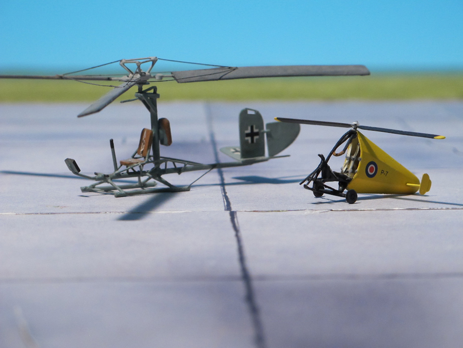
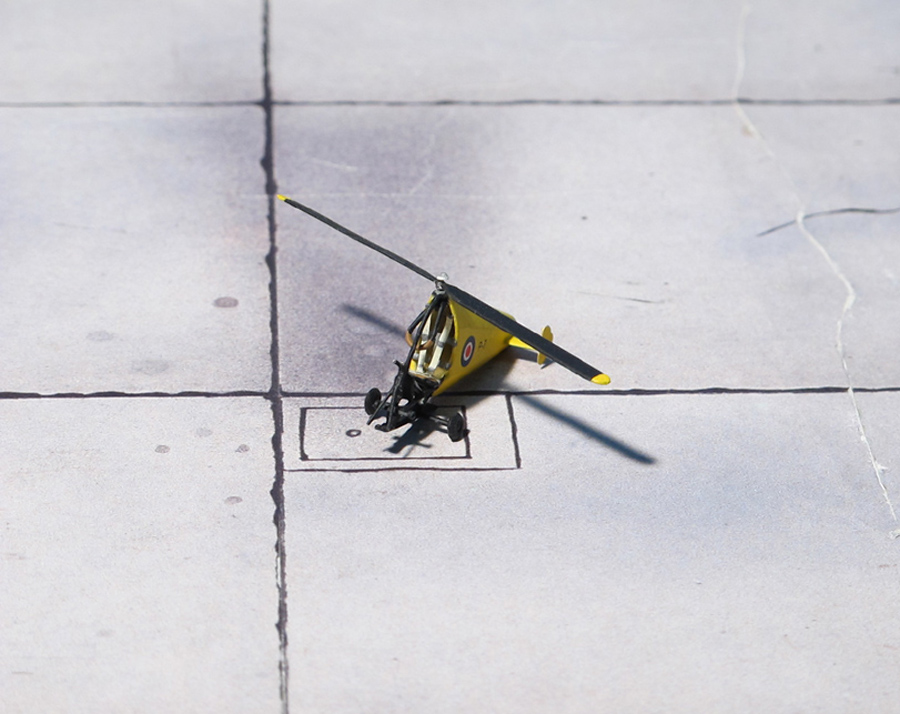
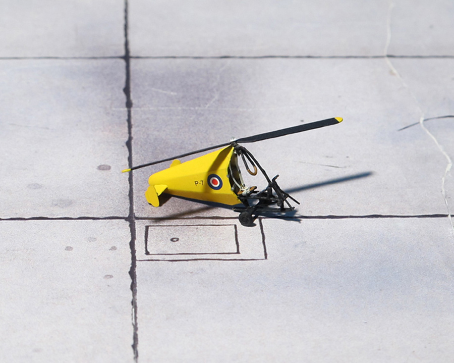
Hafner Rotachute Mk.III
Hafner Rotachute Mk.III
Hafner Rotachute Mk.III
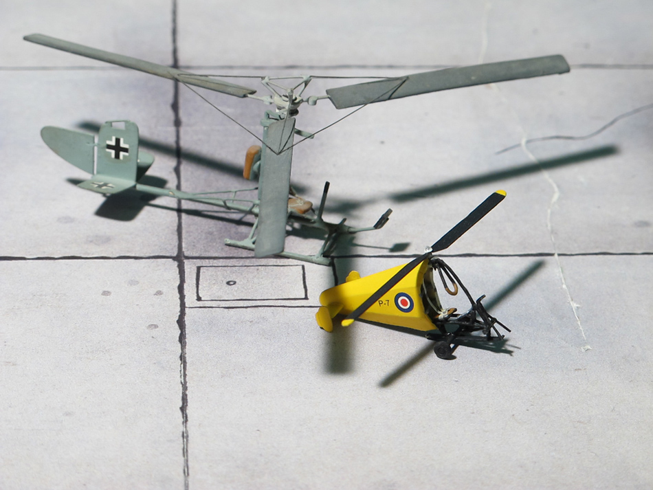
Hafner Rotachute Mk.III and Focke-Achgelis Fa 330 Bachstelze, Scratch built
Hafner Rotachute Mk.III
Hafner Rotachute Mk.III
Hafner Rotachute Mk.III
Hafner Rotachute Mk.III and Focke-Achgelis Fa 330 Bachstelze, Scratch built
Scale 1:72 aircraft models of World War II
Mit der weiteren Nutzung unserer Webseite erklären Sie sich damit einverstanden, dass wir Cookies verwenden um Ihnen die Nutzerfreundlichkeit dieser Webseite zu verbessern. Weitere Informationen zum Datenschutz finden Sie in unserer Datenschutzerklärung.