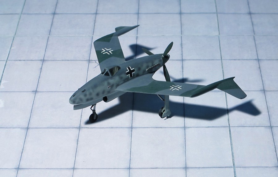
TYPE: Interceptor, fighter
ACCOMMODATION: Pilot only
POWER PLANT: One Daimler-Benz DB 603L liquid-cooled engine, rated at 2,100 hp
PERFORMANCE: 491 mph
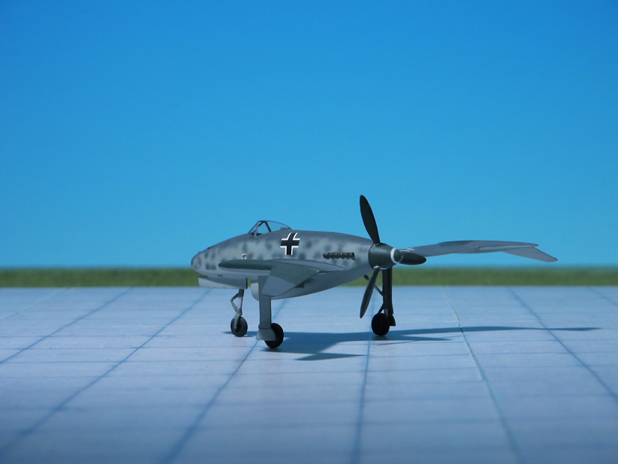
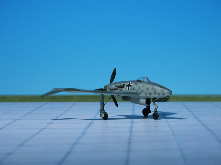
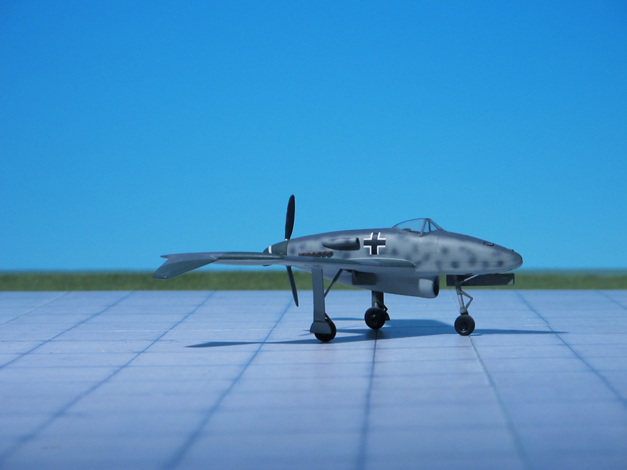
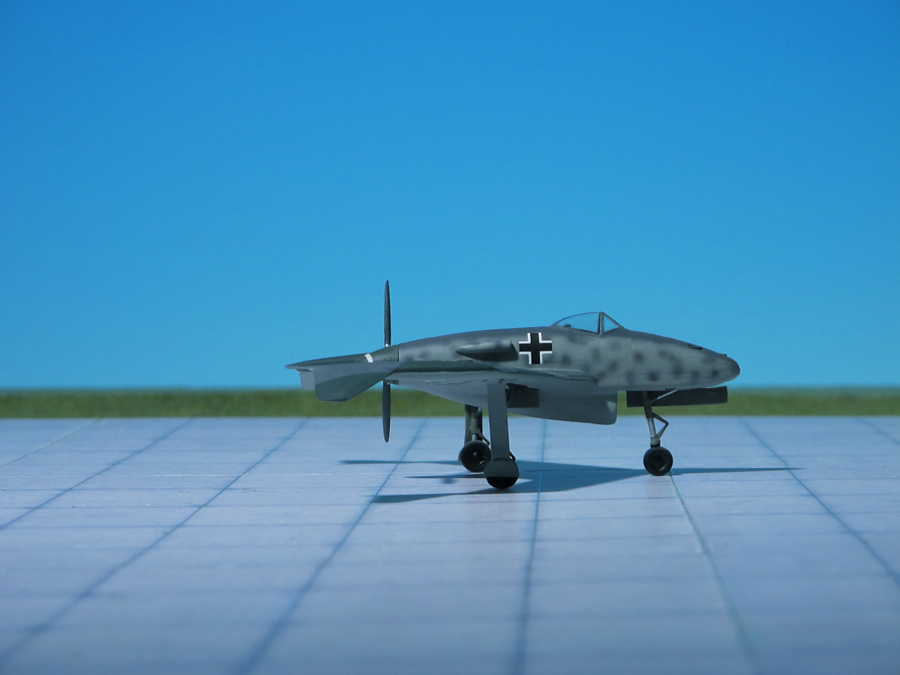
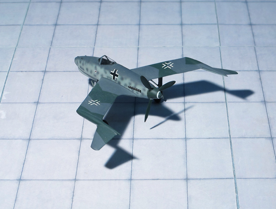
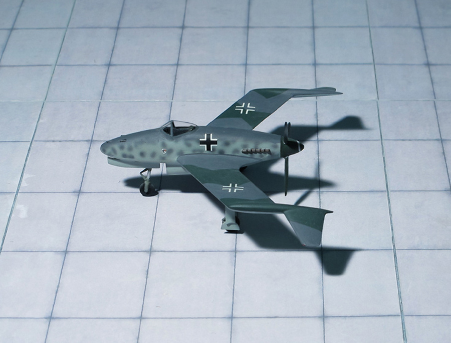
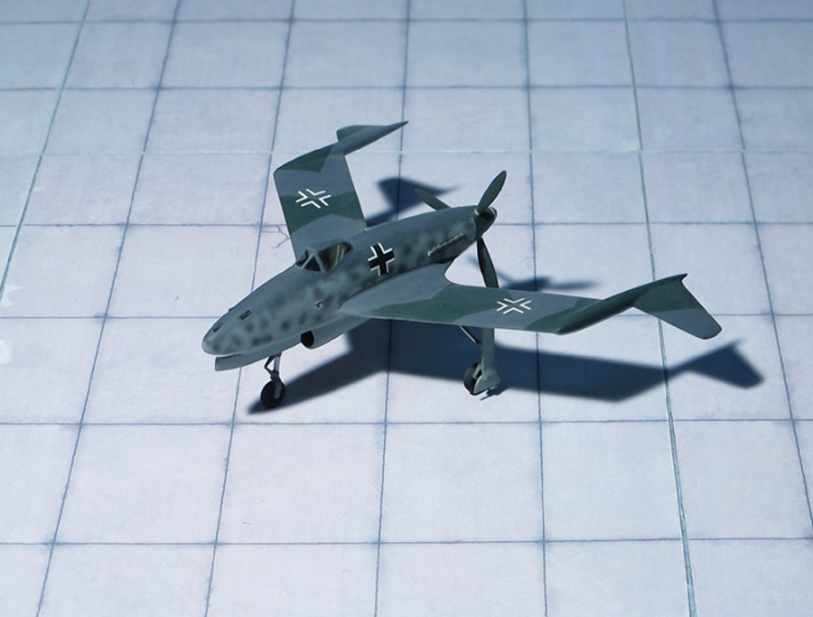
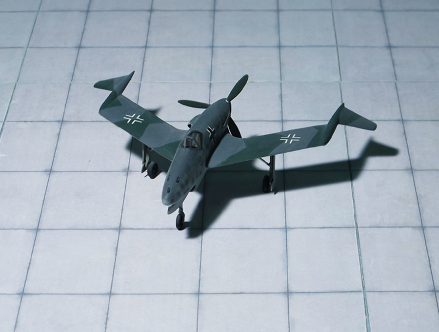
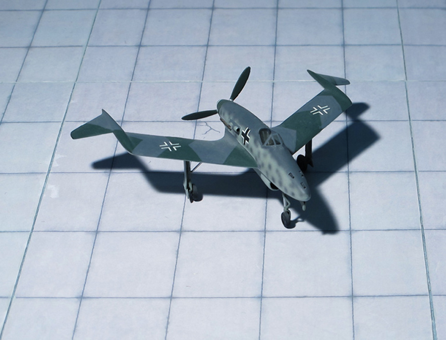
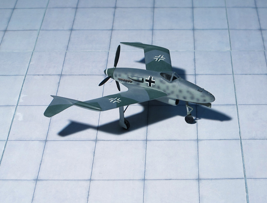
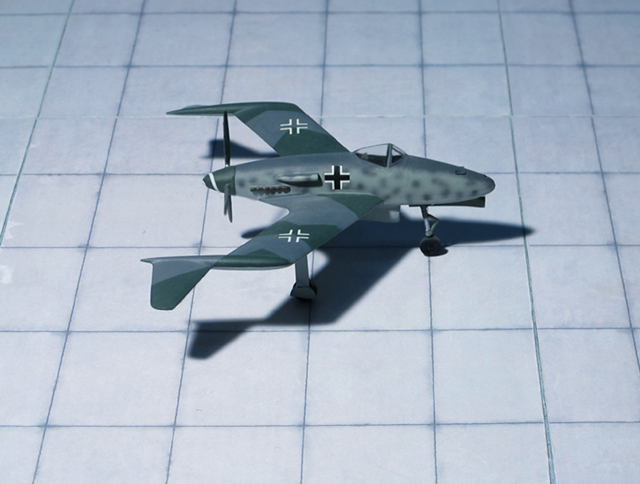
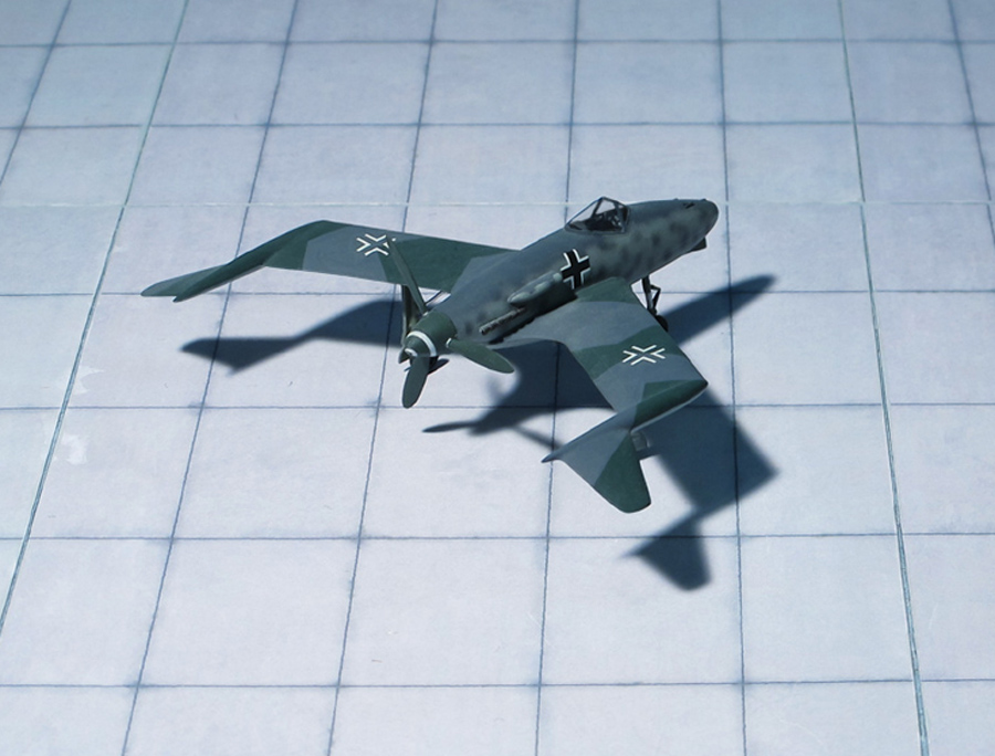
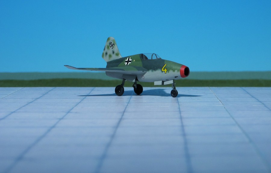
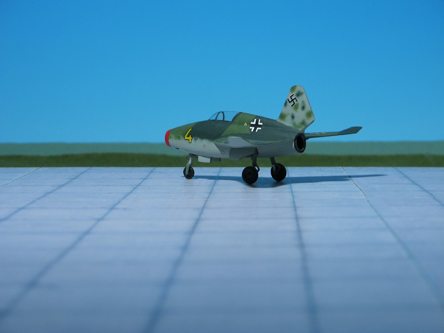
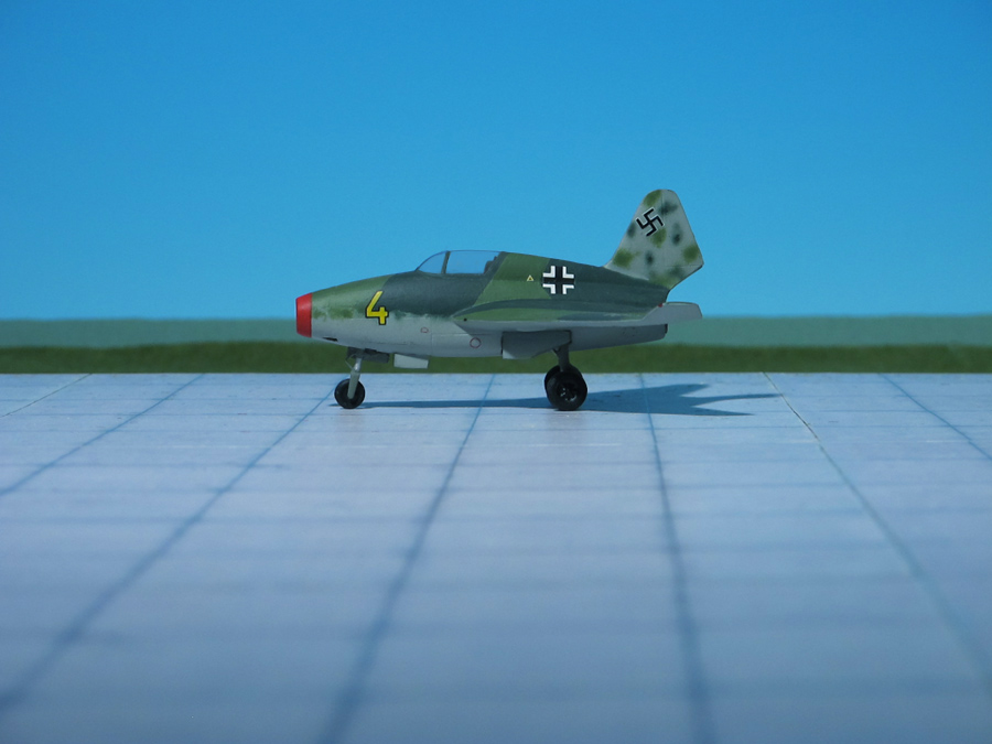
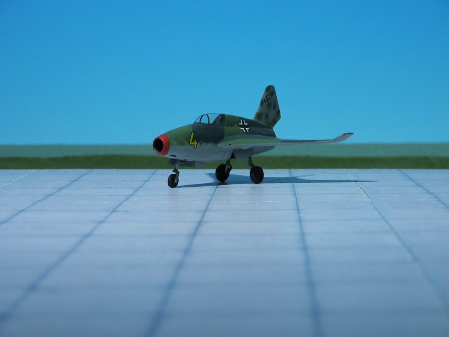
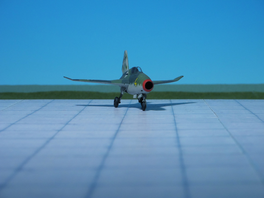
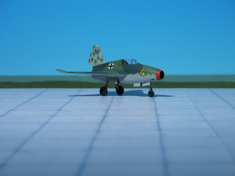
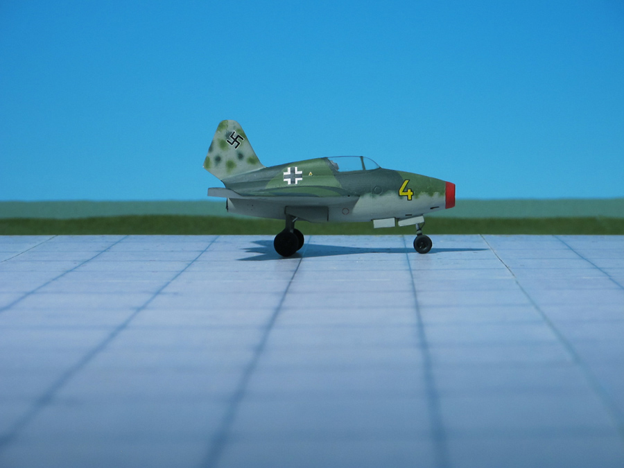
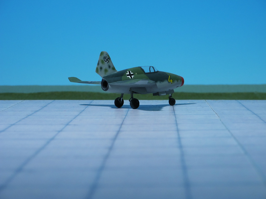
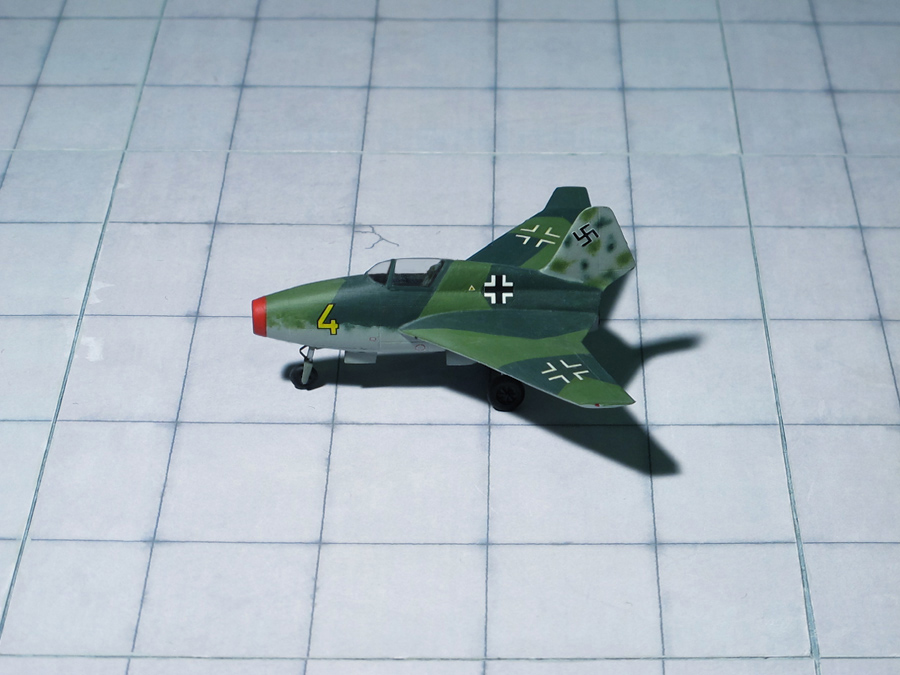
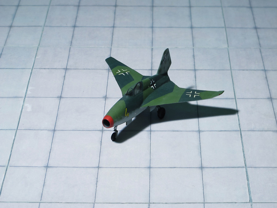
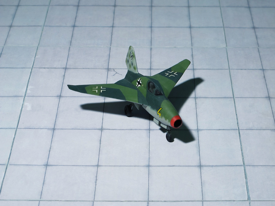
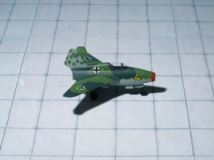
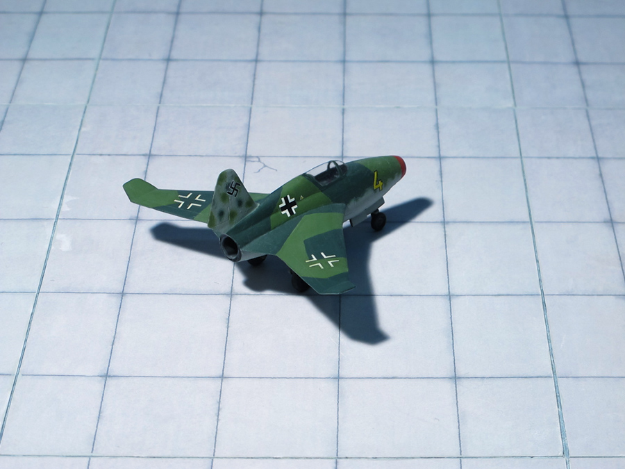
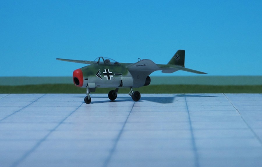
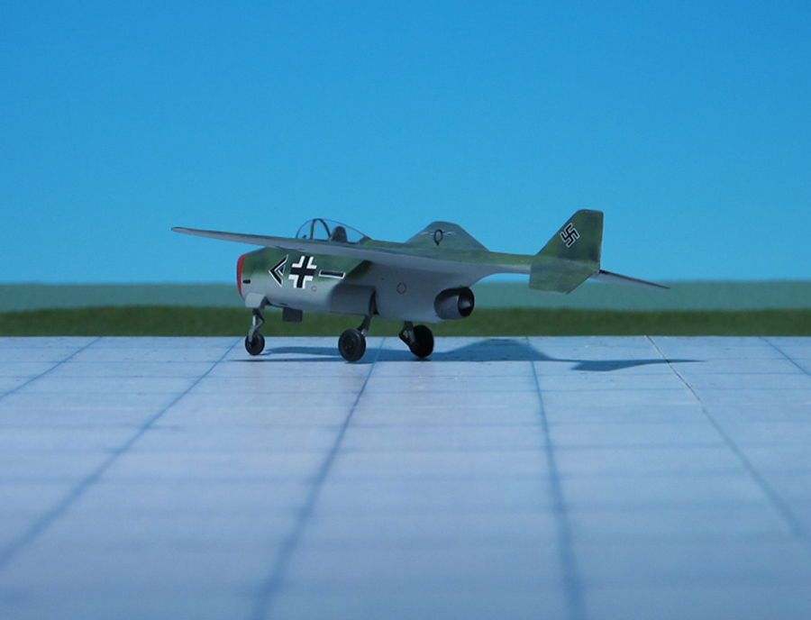
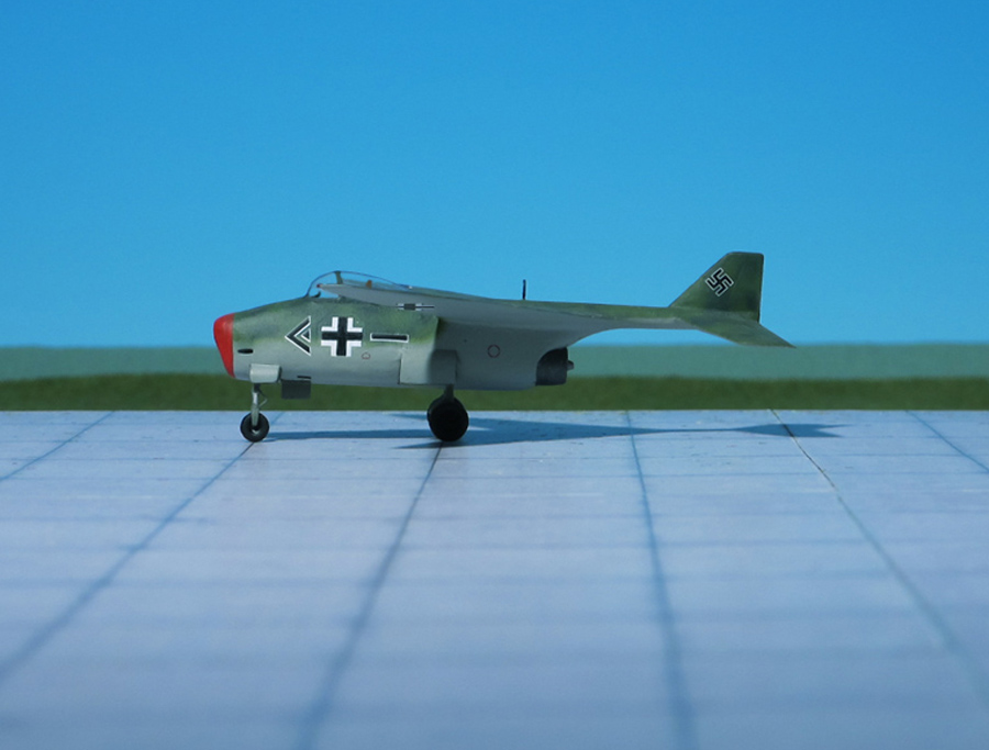
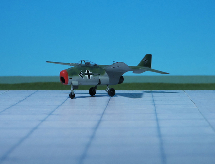
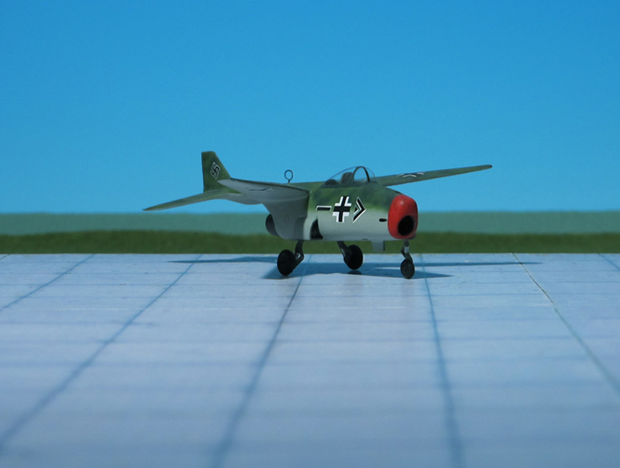
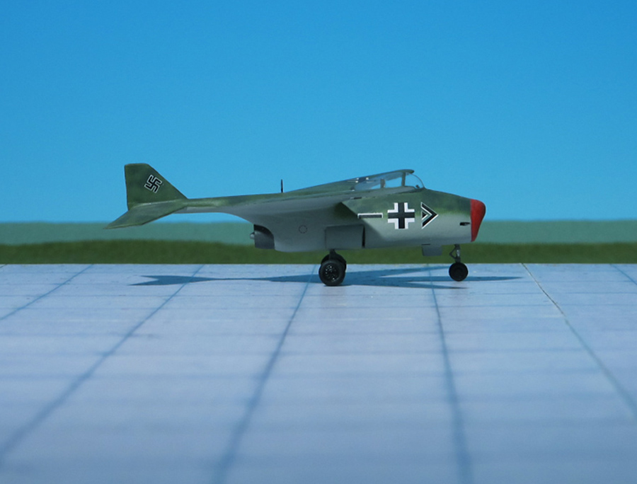
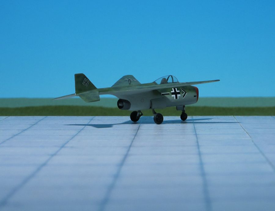
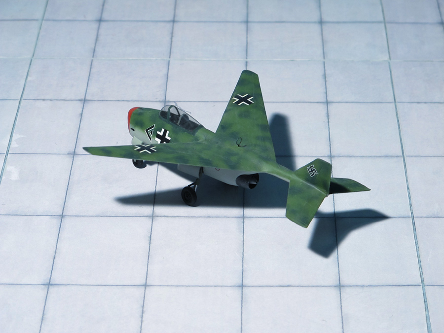
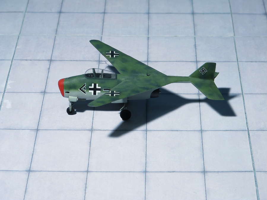
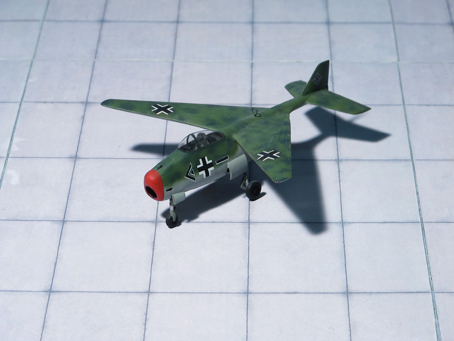
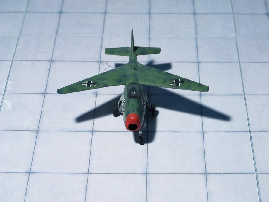
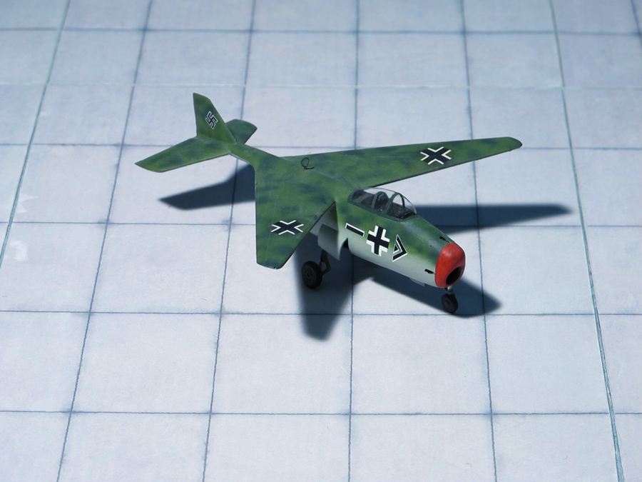
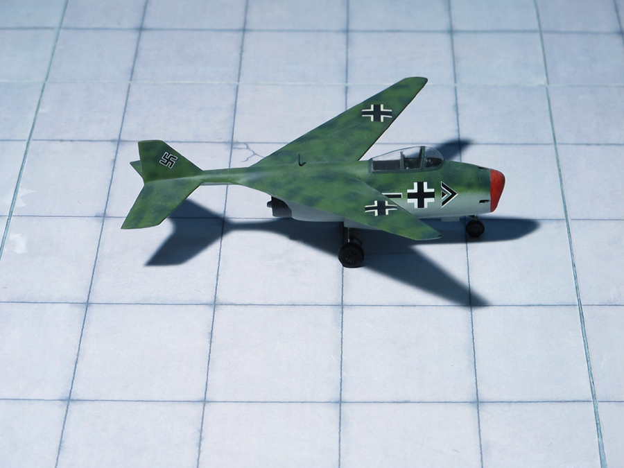
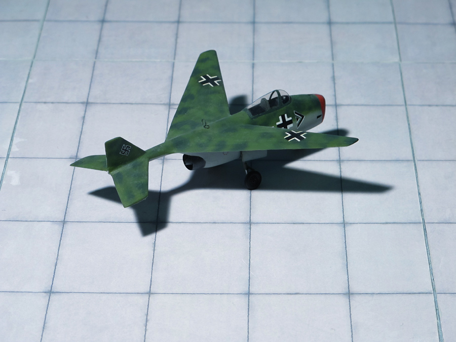
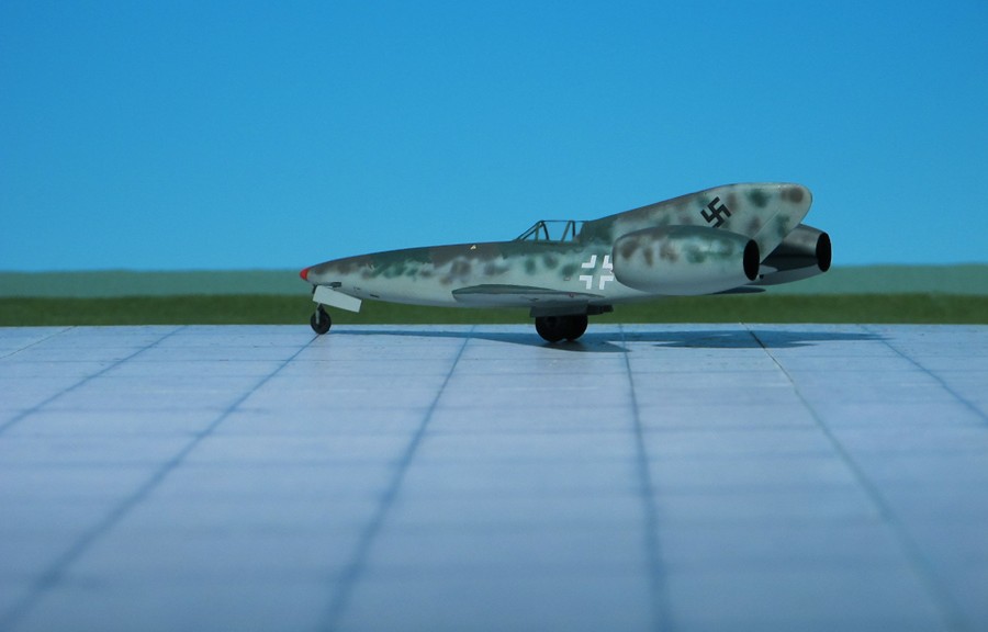
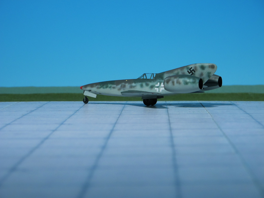
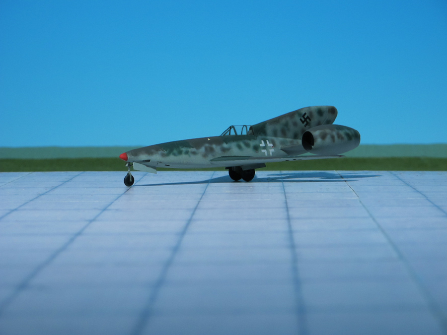
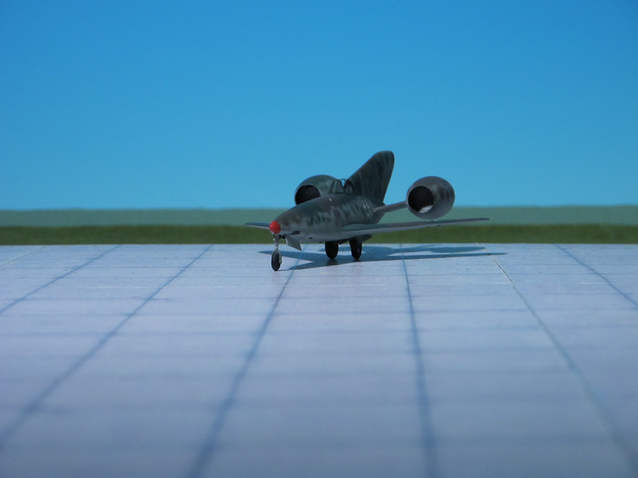
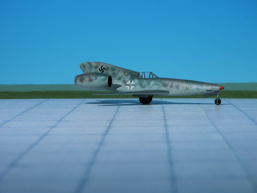
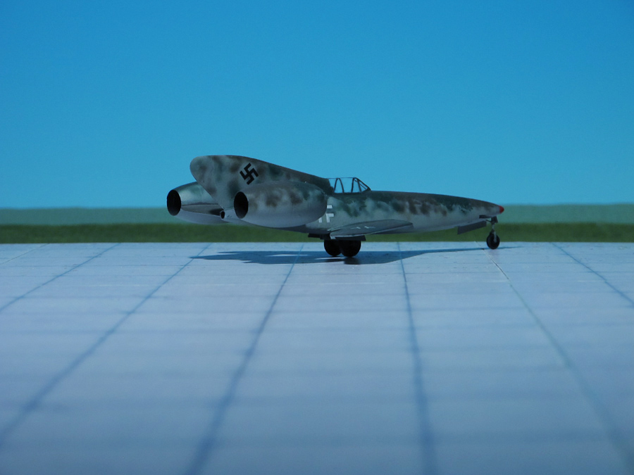
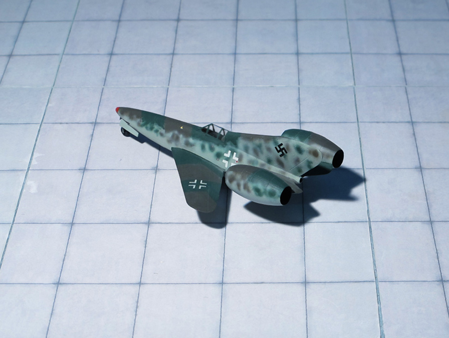
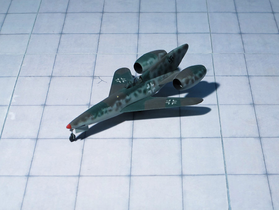
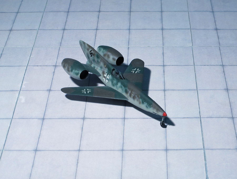
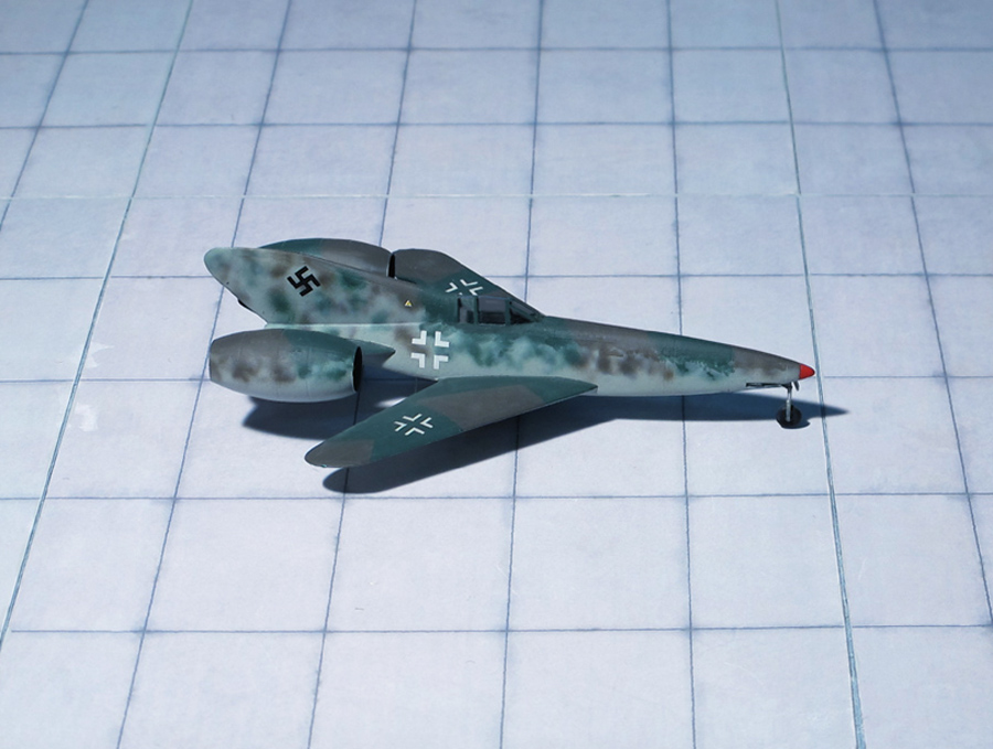
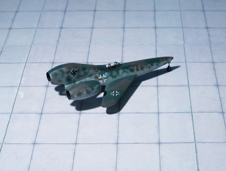
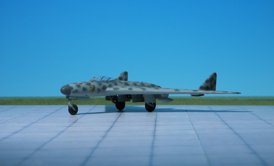
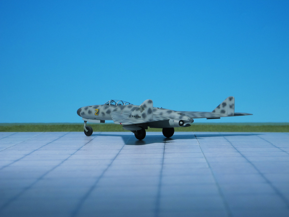
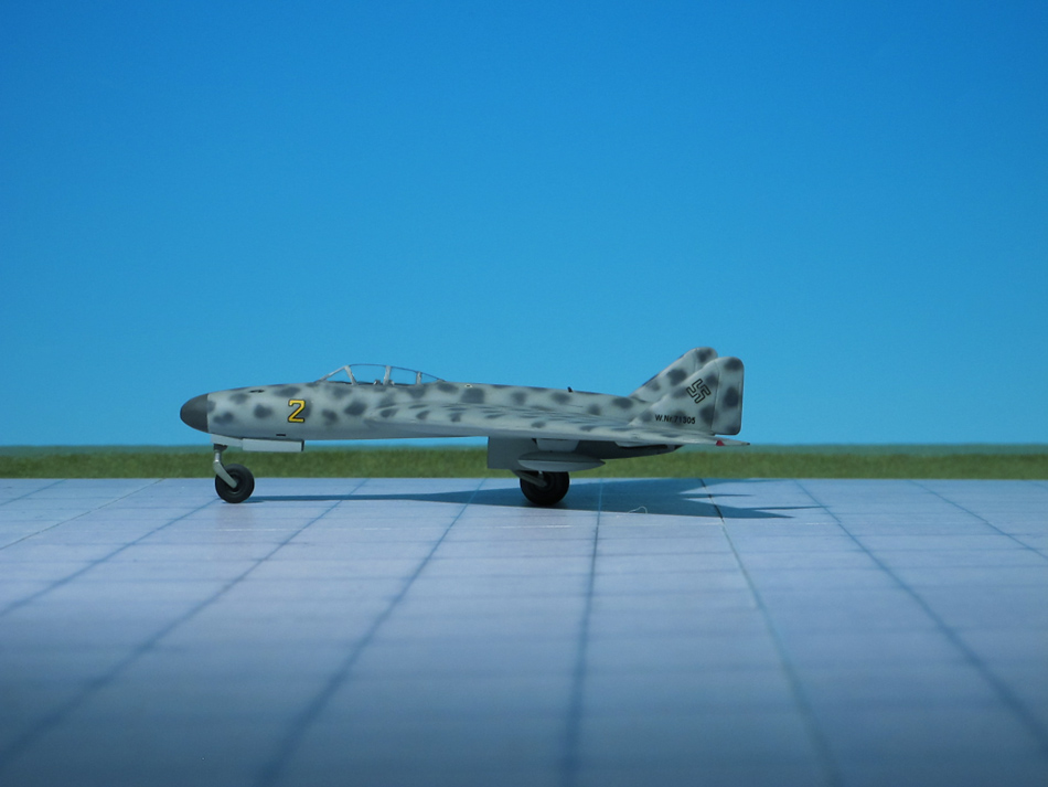
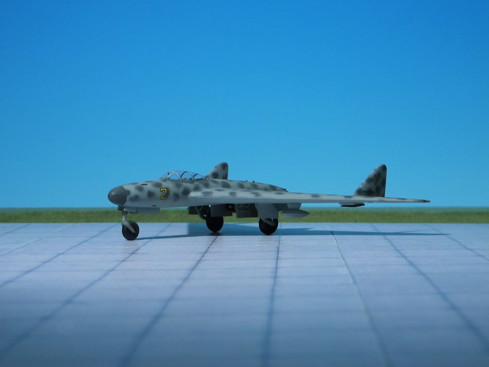
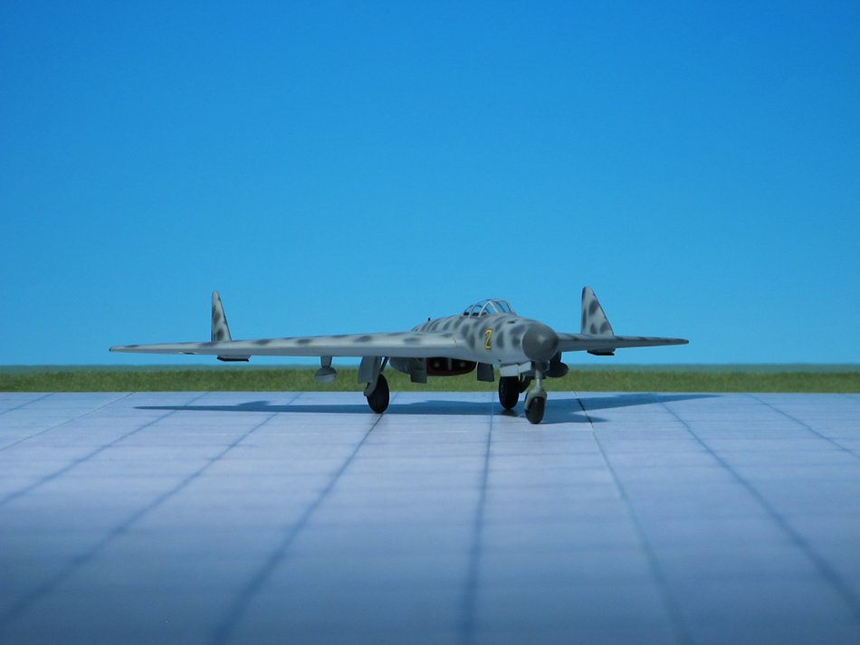
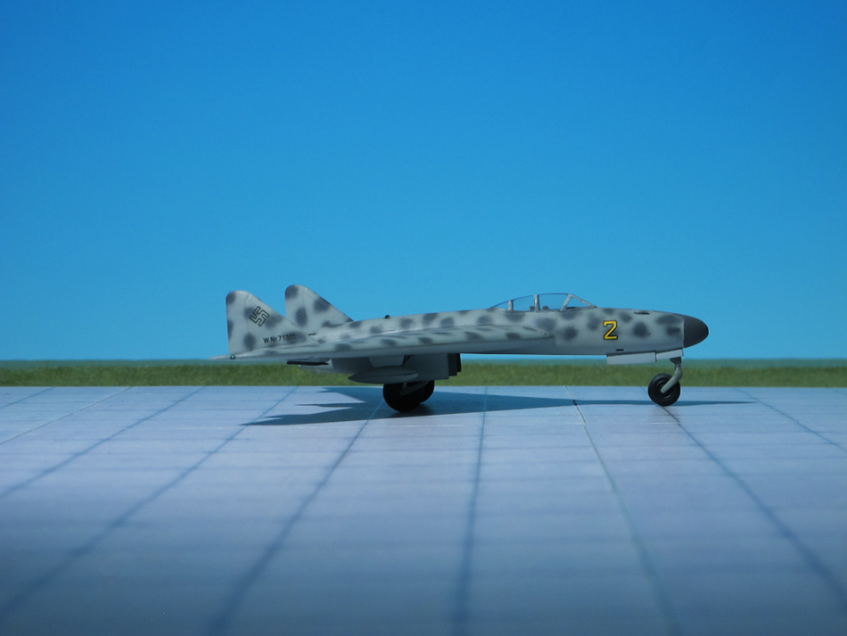
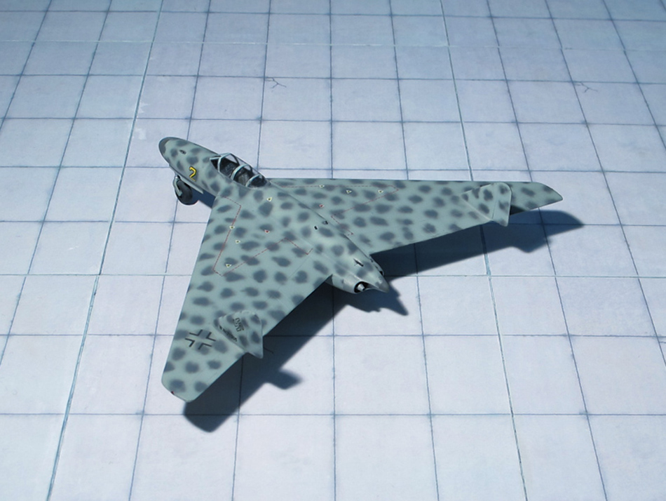
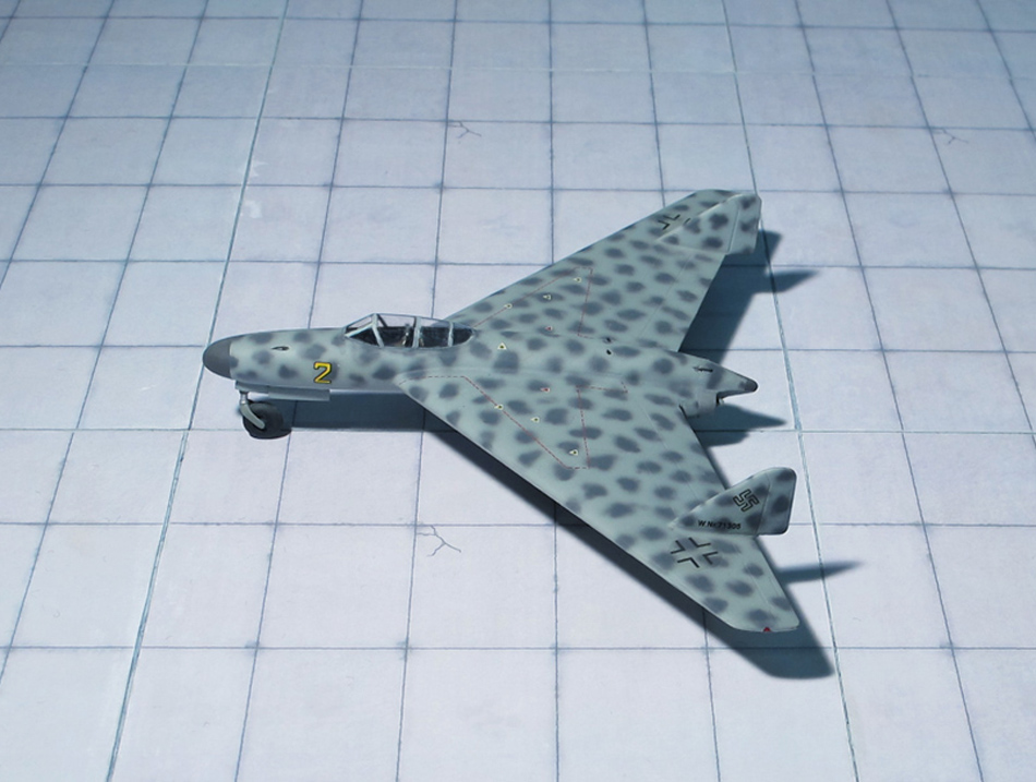
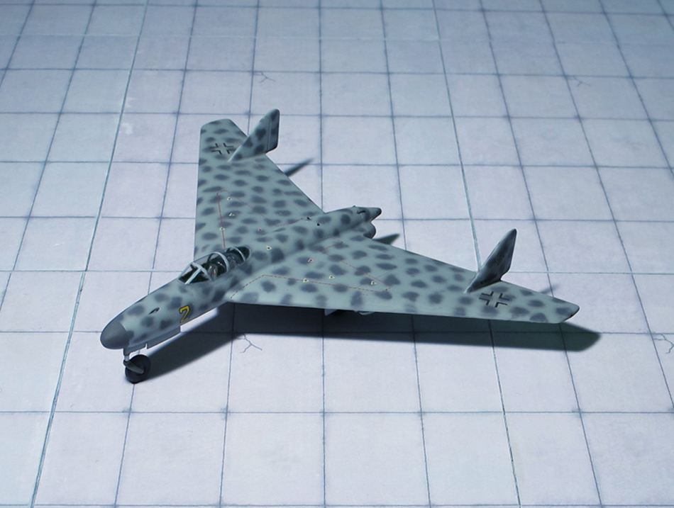
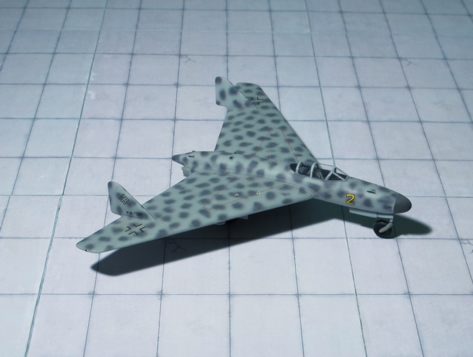
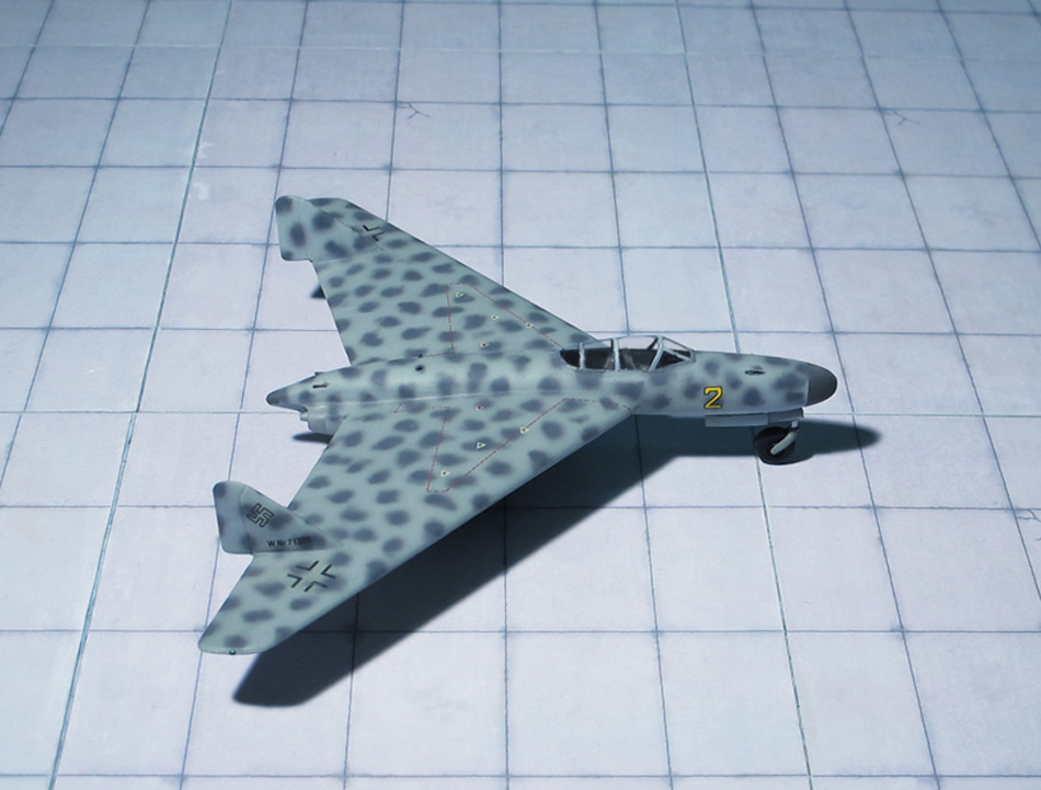
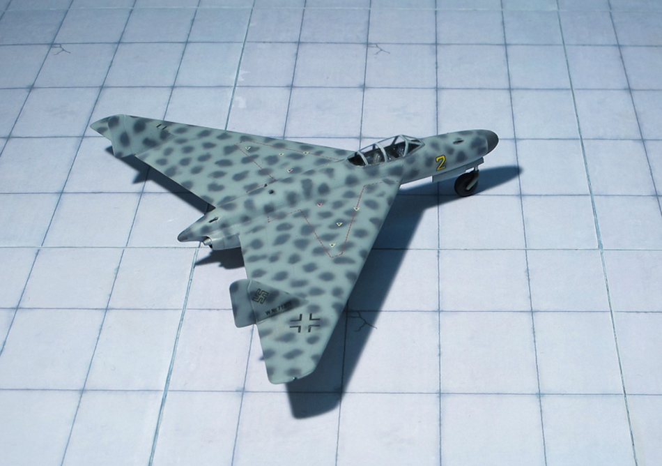
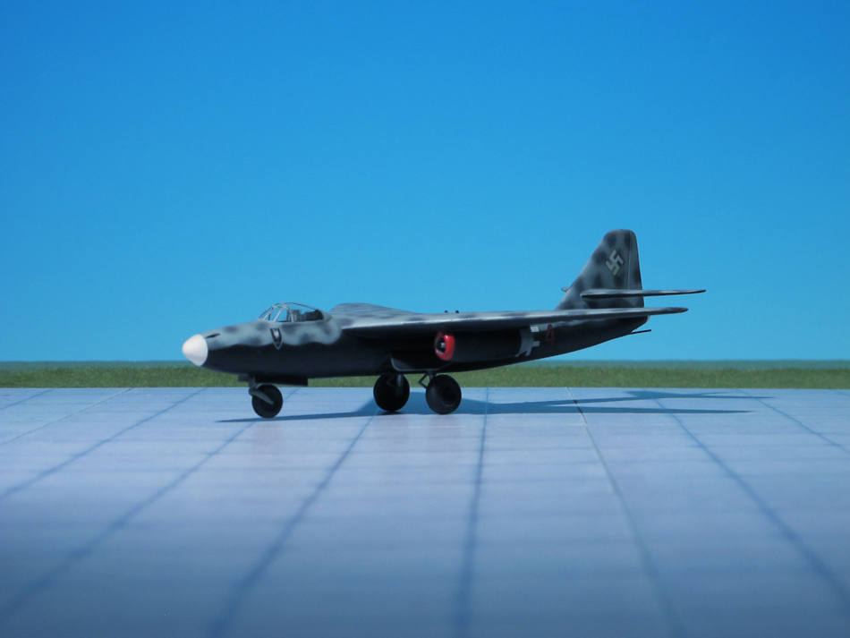
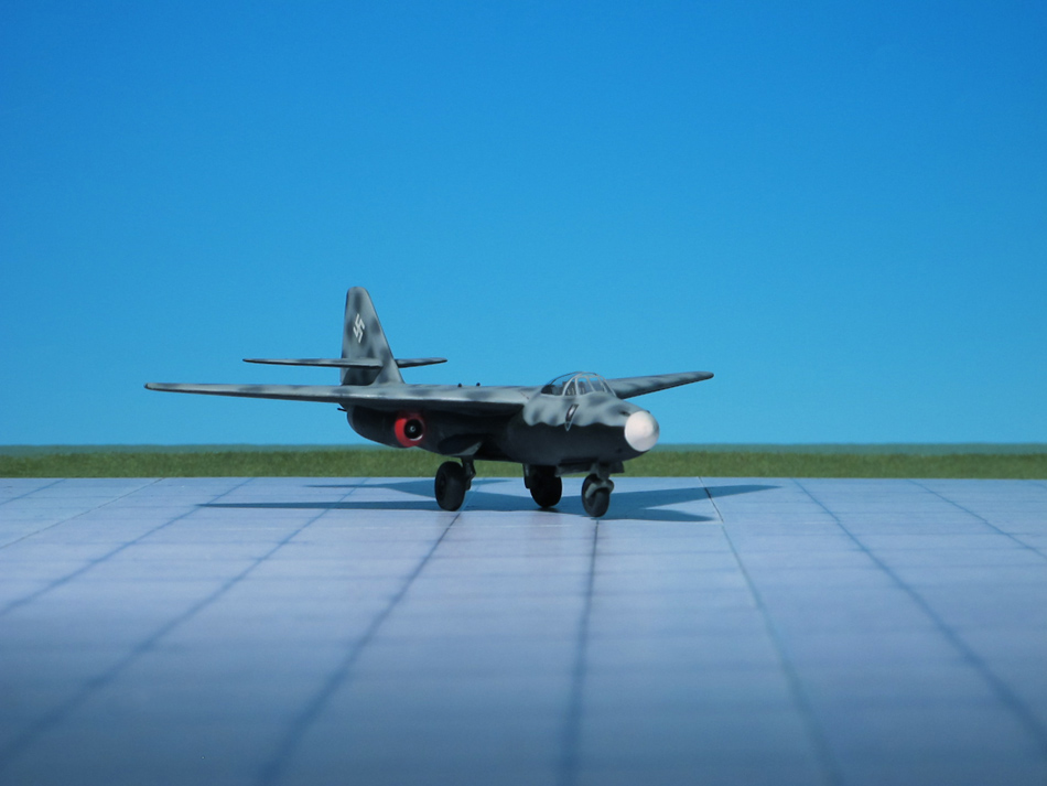
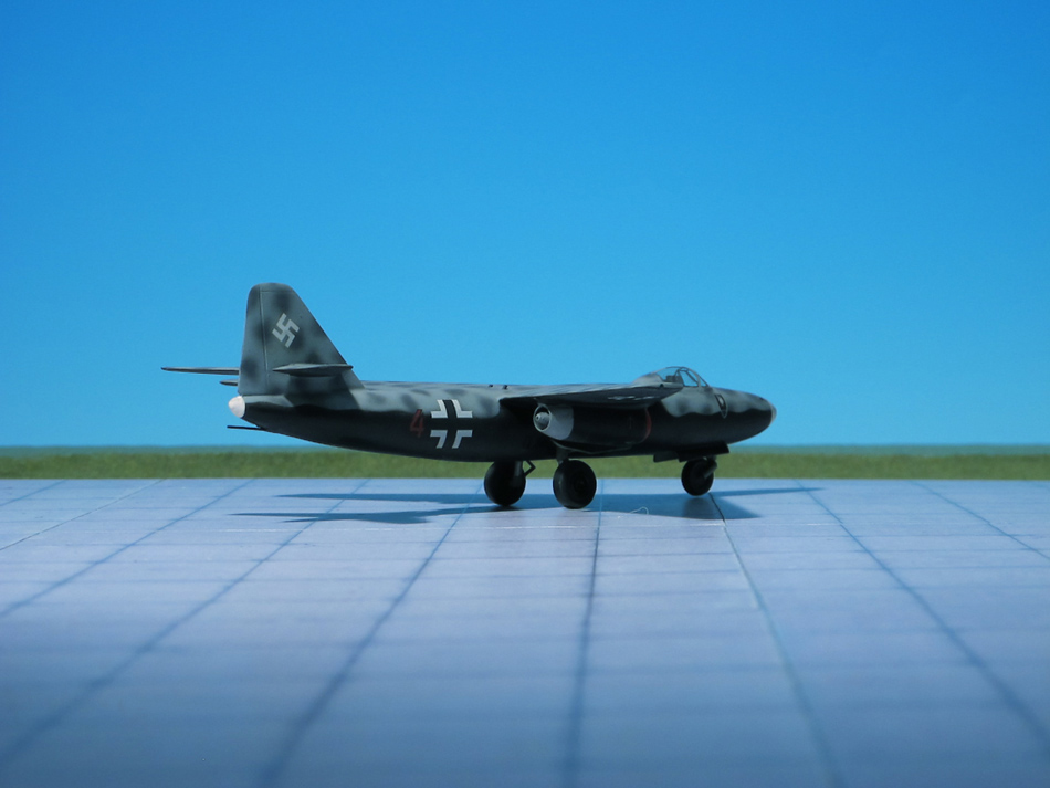
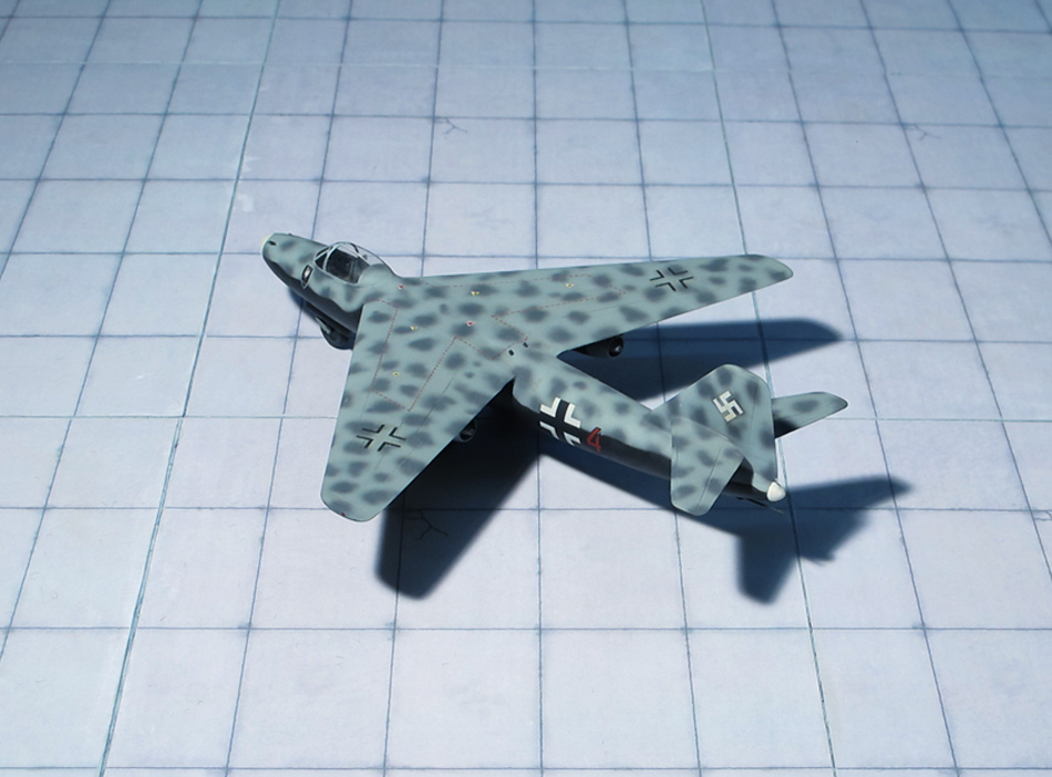
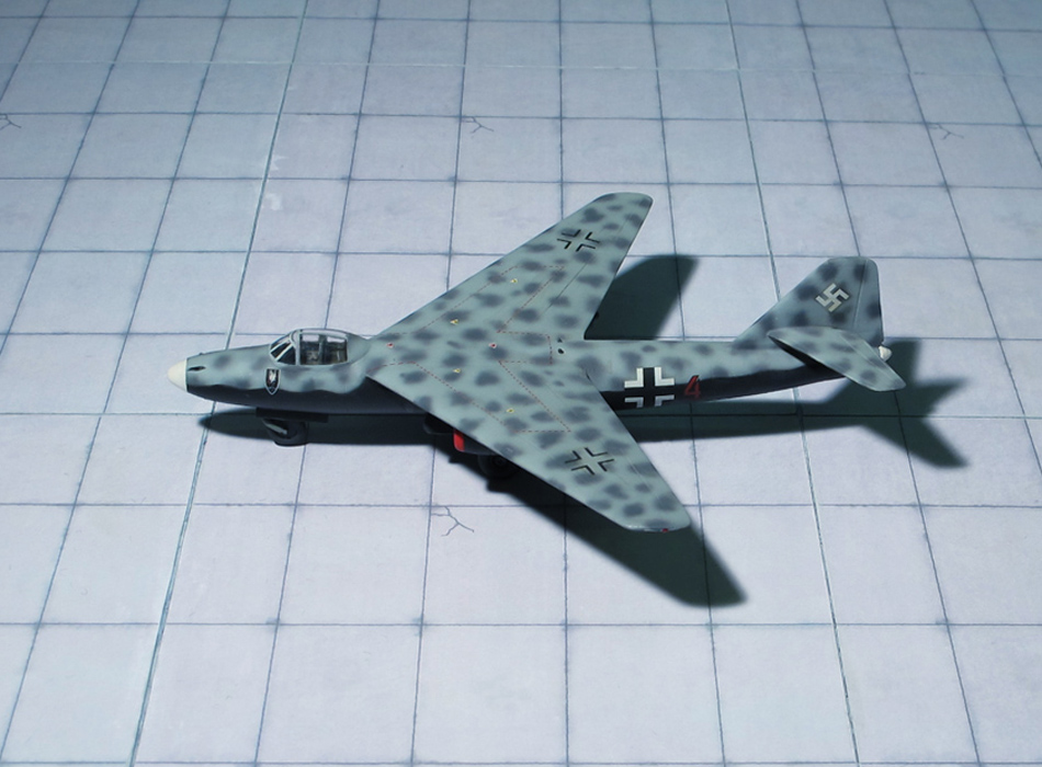
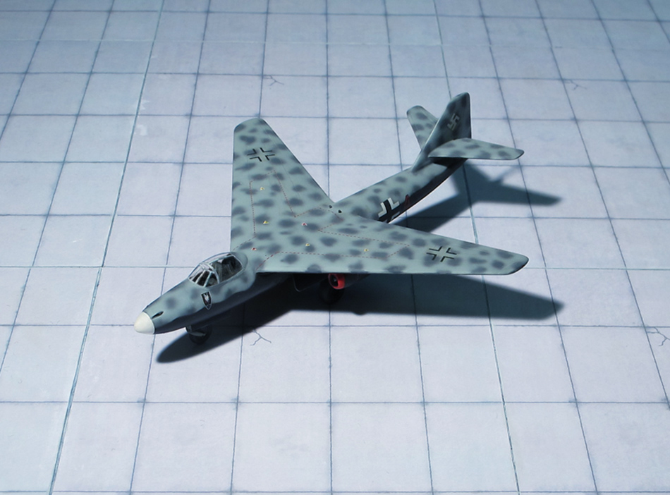
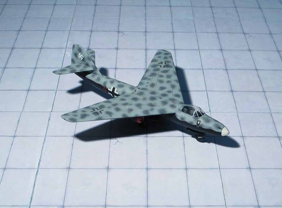
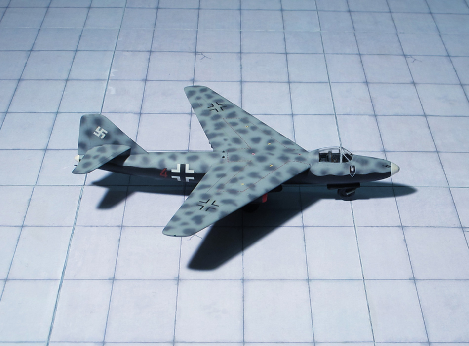
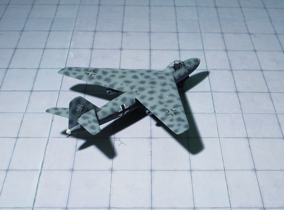
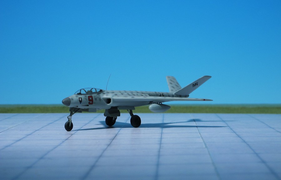
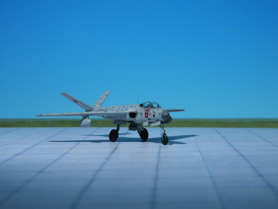
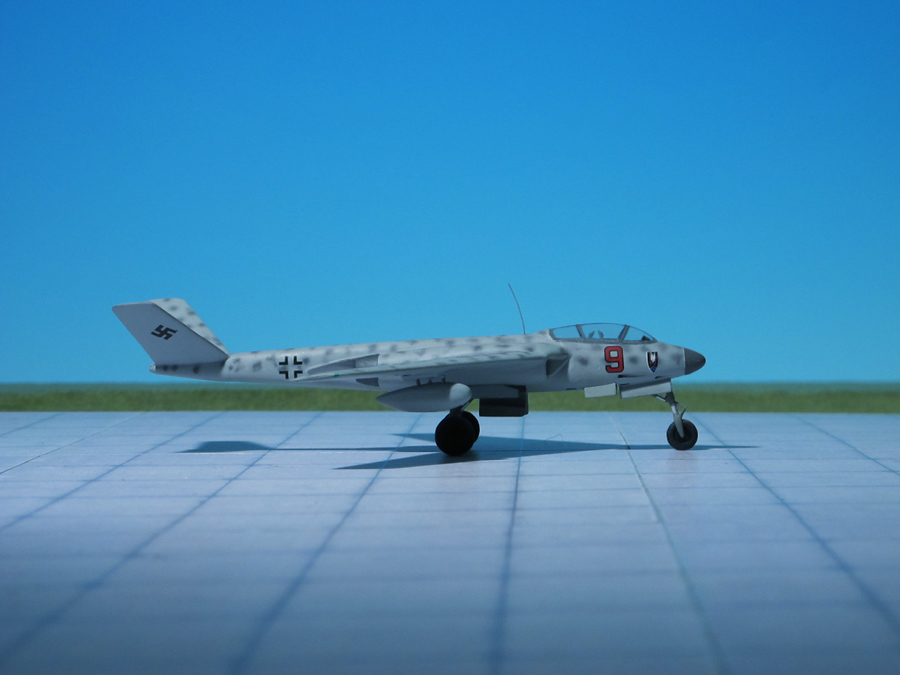
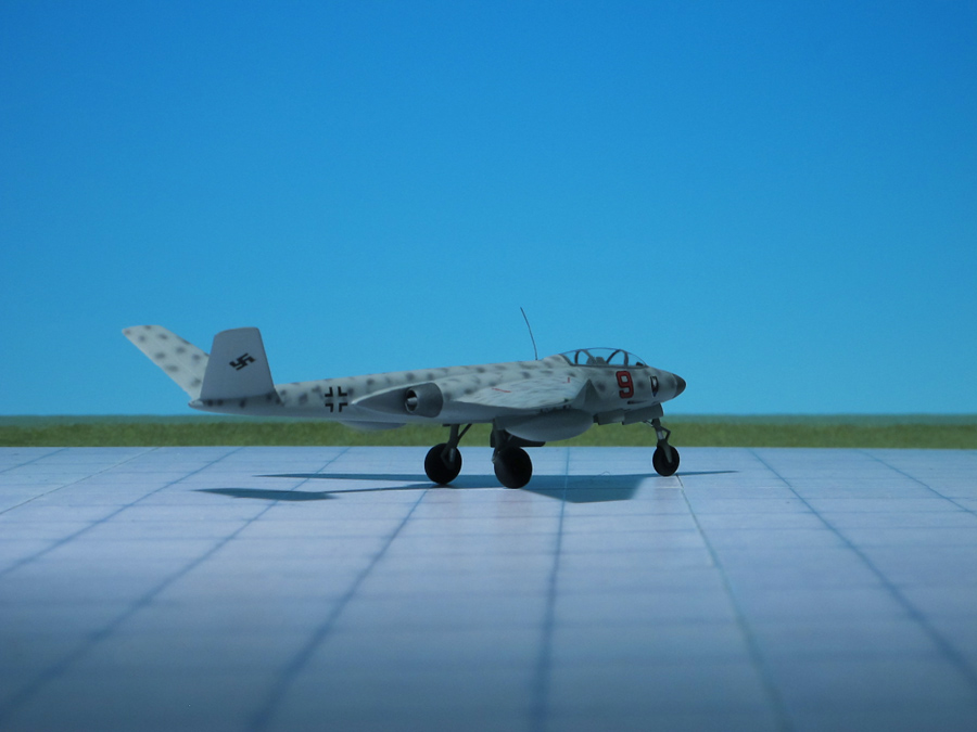
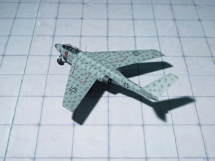
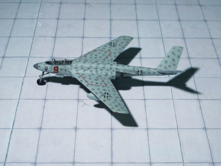
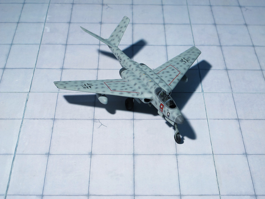
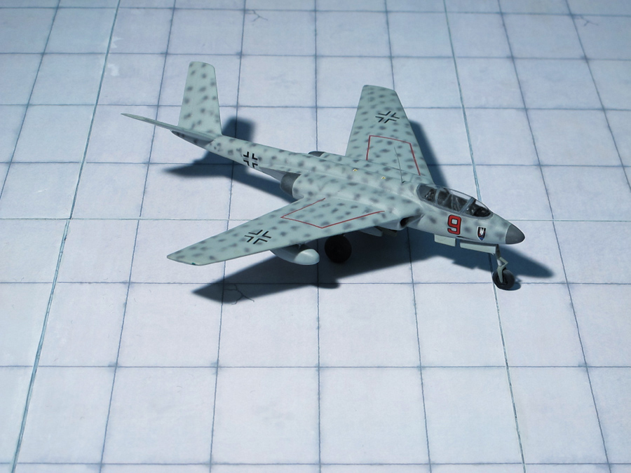
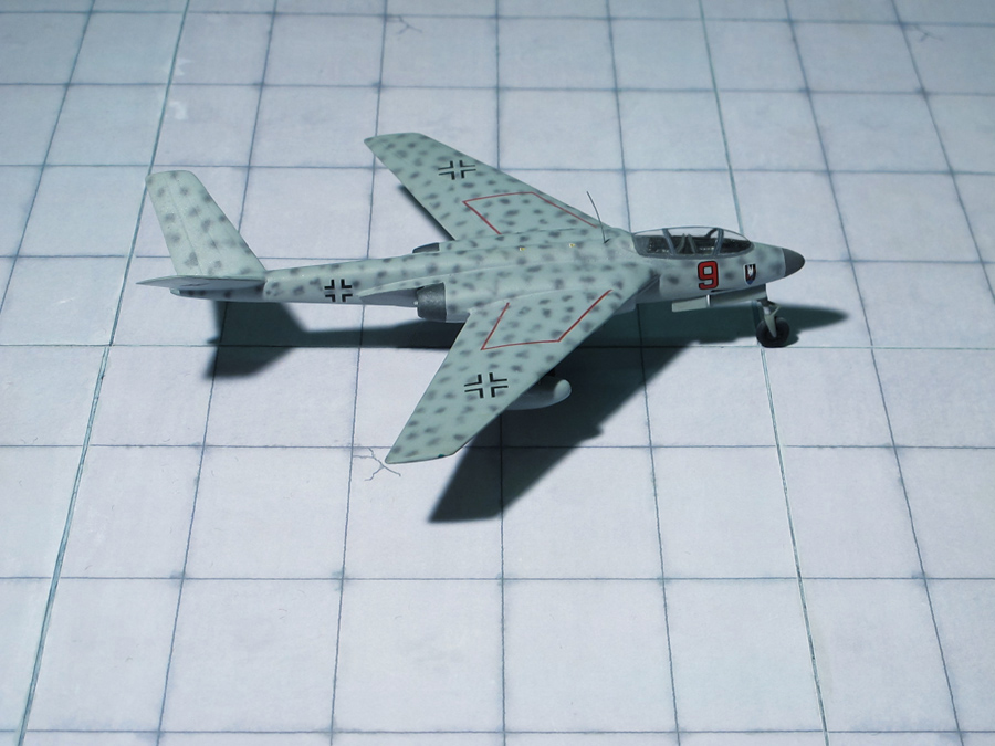
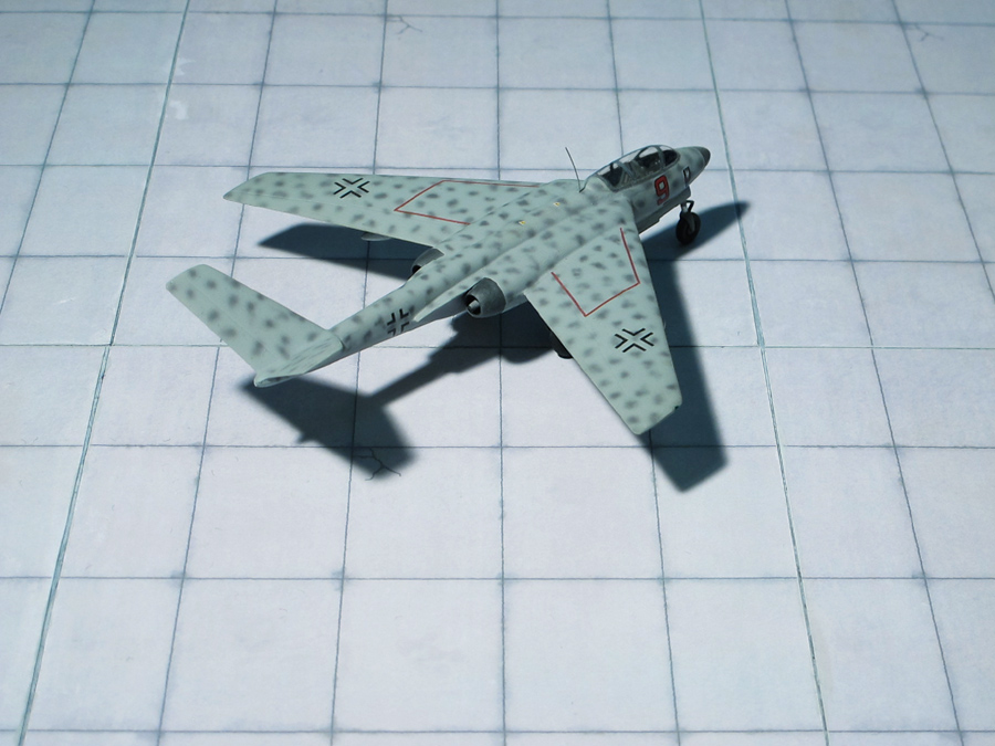
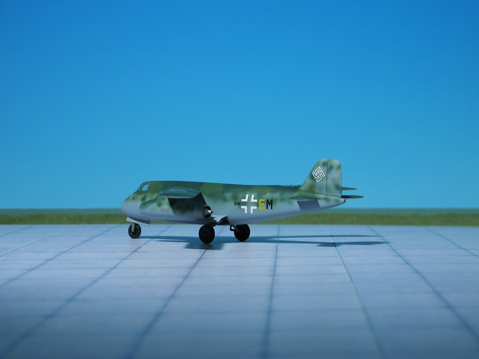
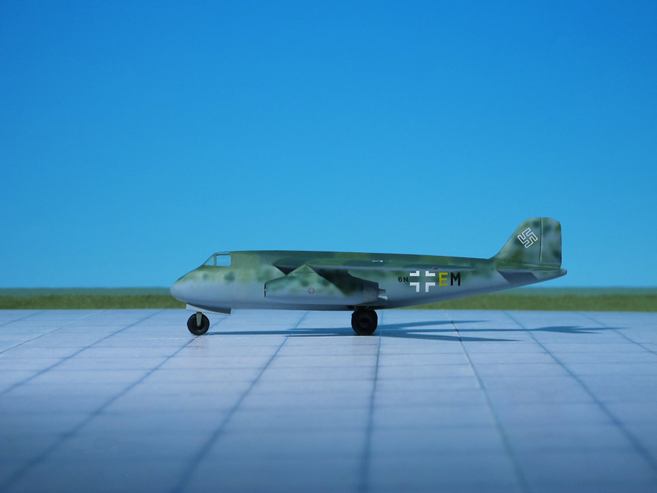
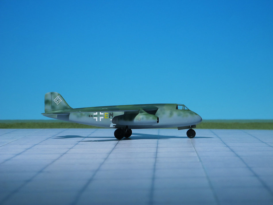
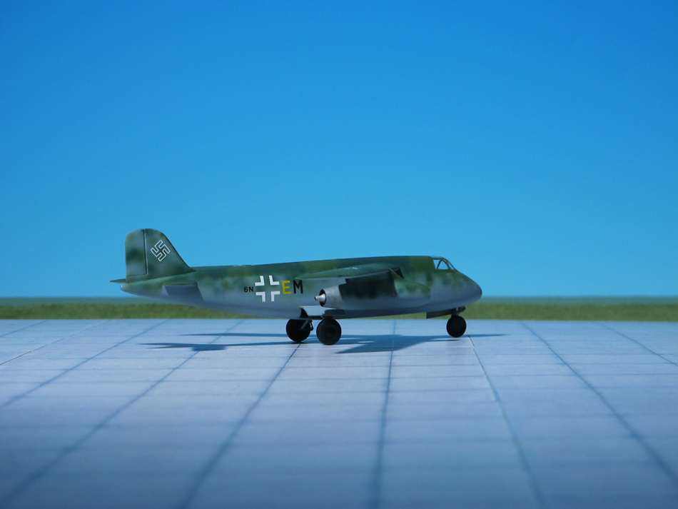
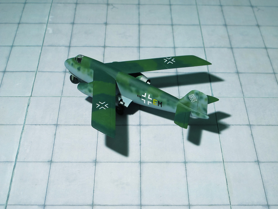
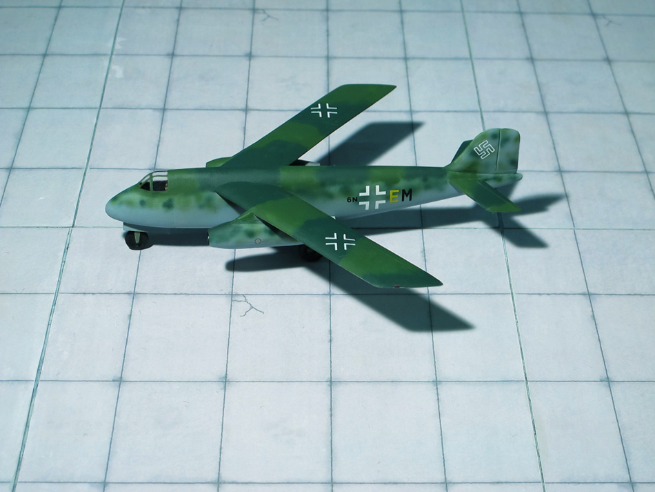
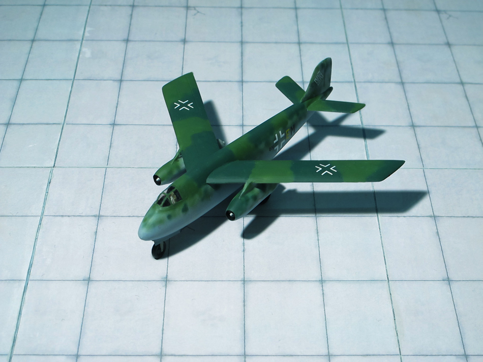
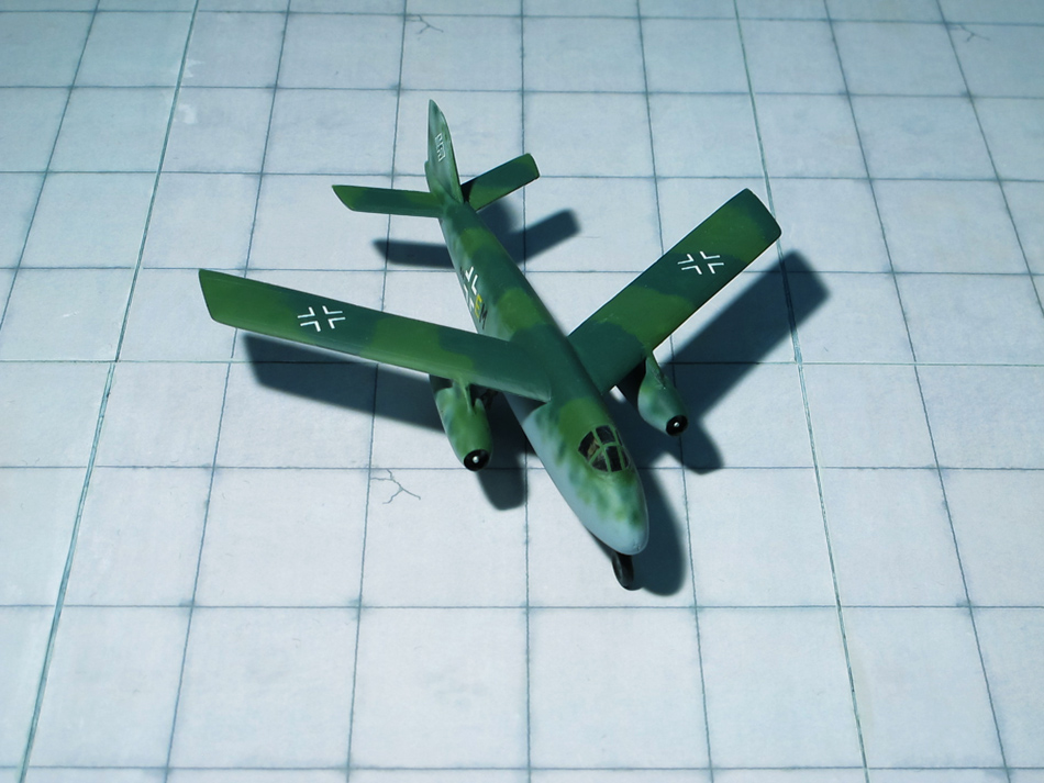
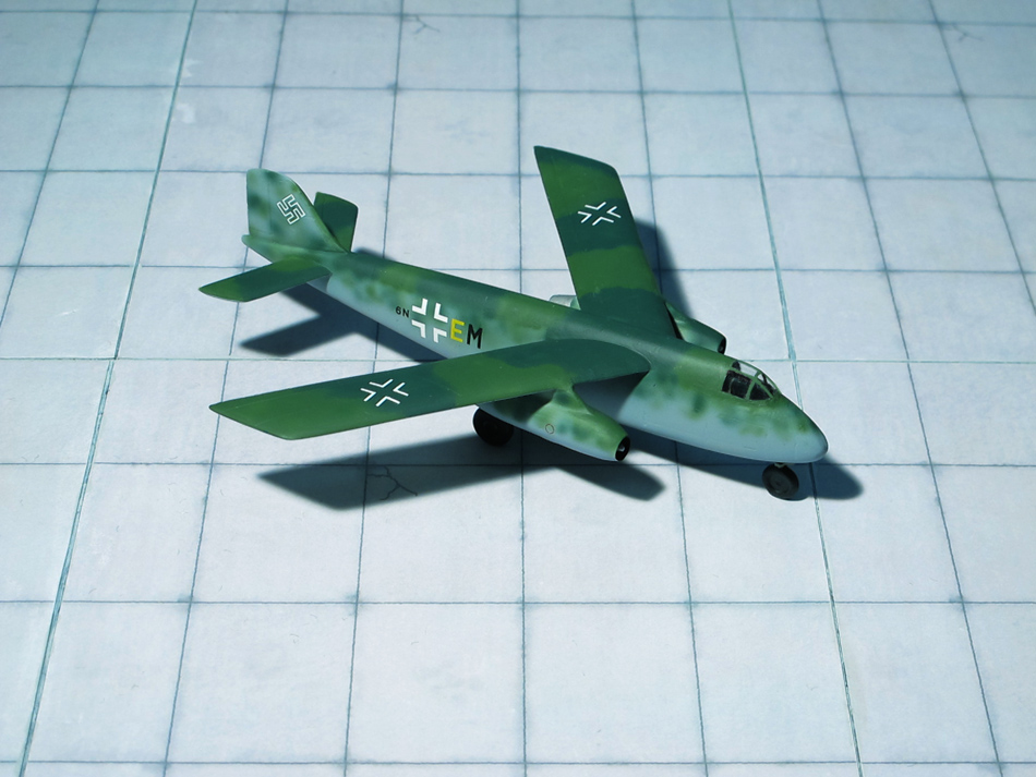
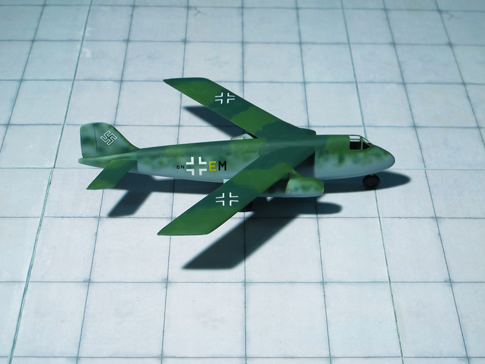
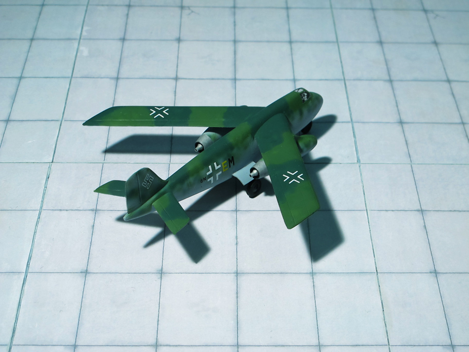
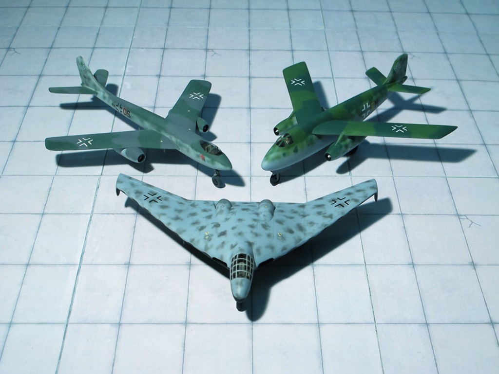
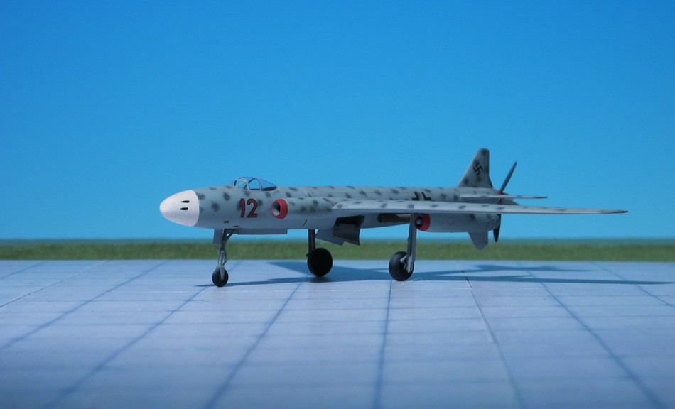
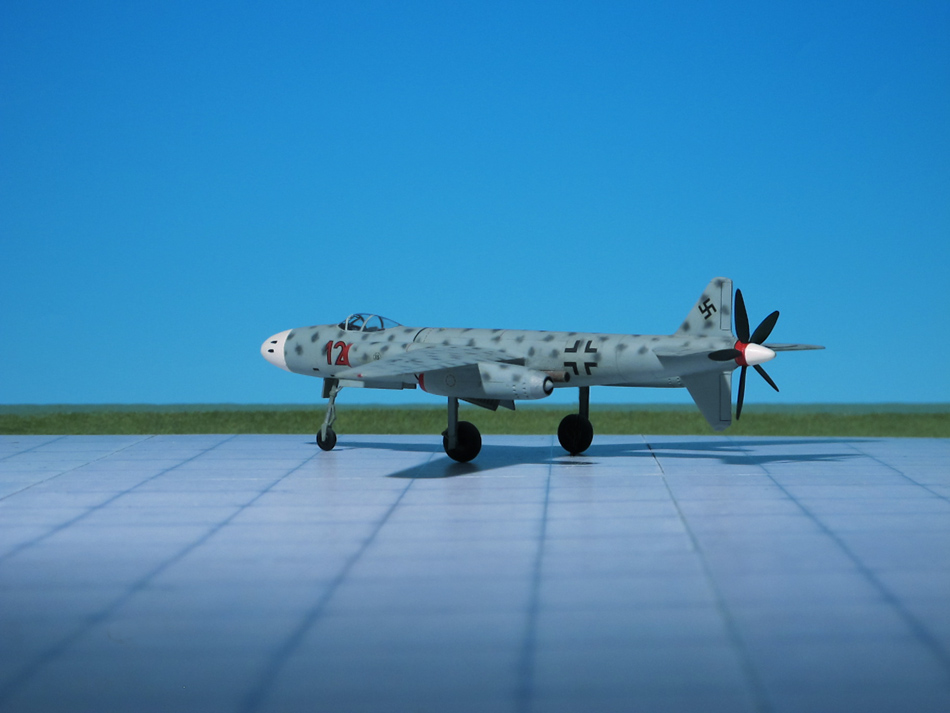
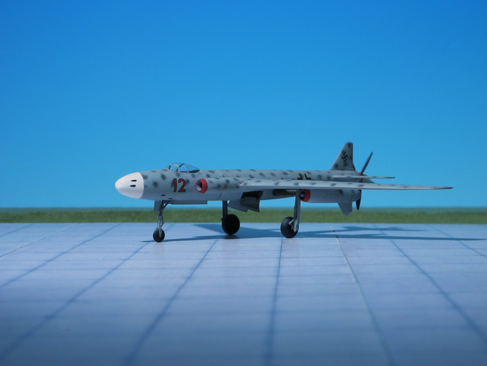
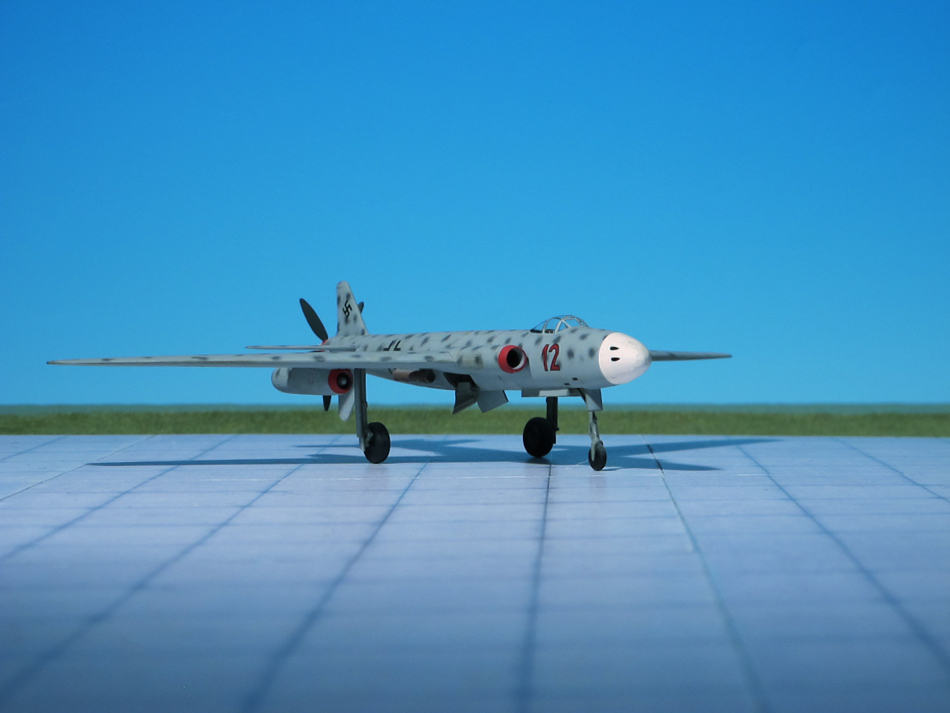
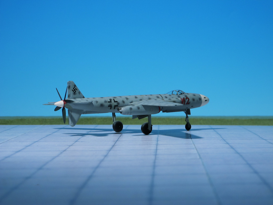
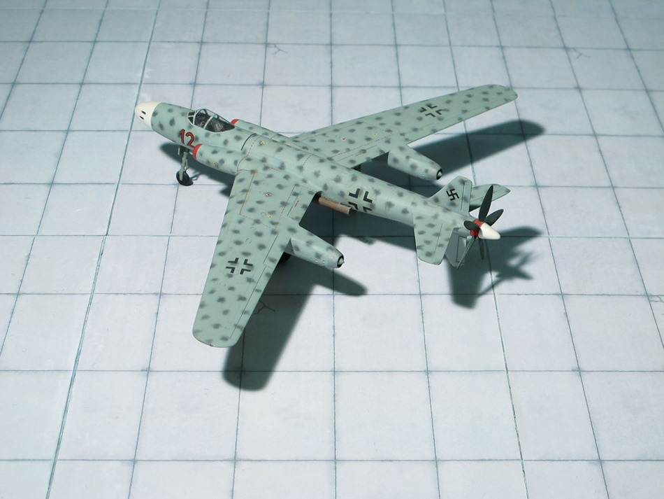
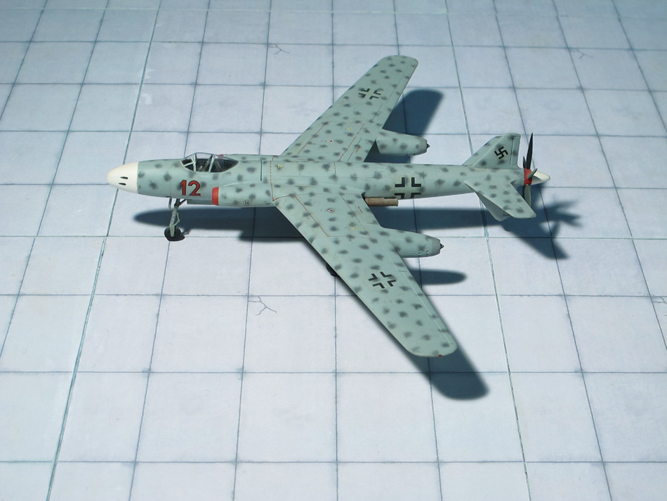
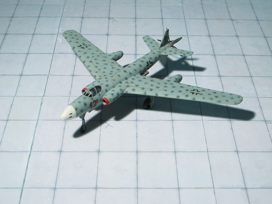
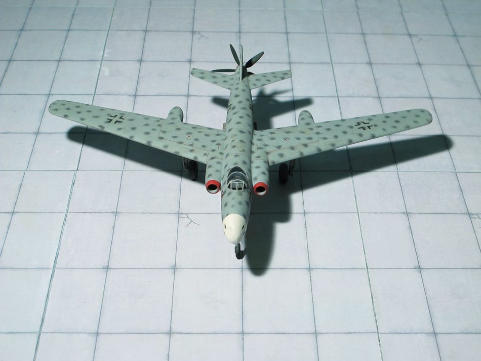
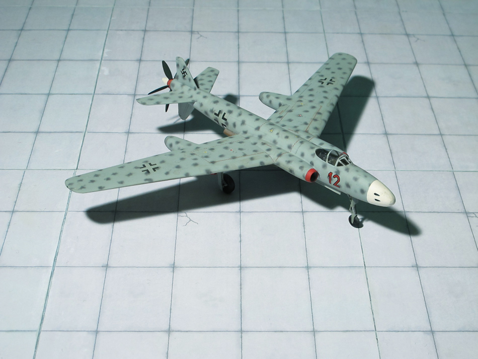
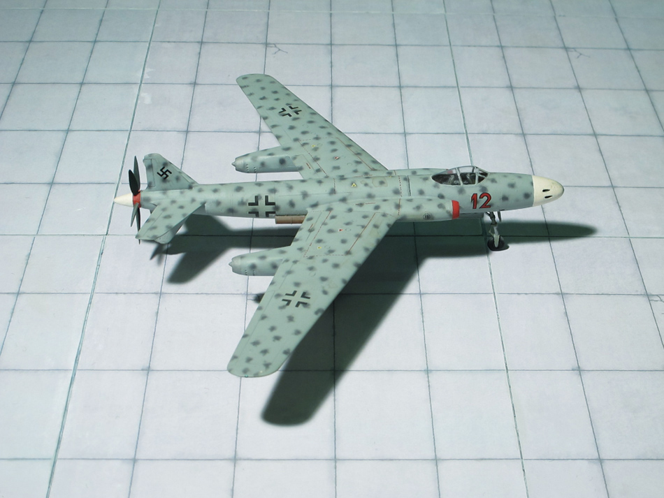
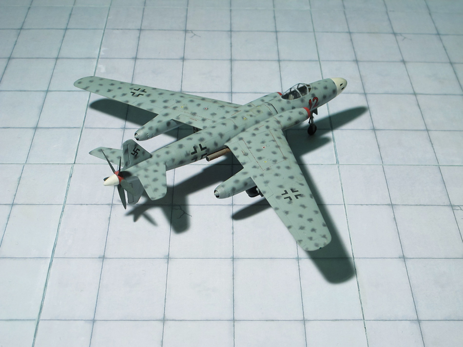
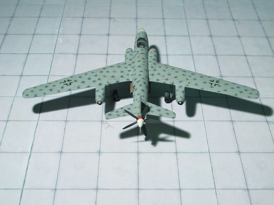
COMMENT: In autumn 1944 the Blohm & Voss team worked on a high performance, piston engine powered fighter aircraft under the internal designation P.208. From the onset the design was a tailless aircraft, the engine imbedded in the aft fuselage behind the cockpit. The advantage of the design was seen in a reduction of the fuselages surface to reduce drag, the abstinence of an extension shaft to drive the pusher propeller, and lower costs and production time. The engine was fed by an air intake located on the starboard side of the fuselage, with the radiator mounted beneath the fuselage. The cantilevered wings were swept back at 30 degrees and were of a constant cross section. Downturned wingtips were connected aft of the main wing trailing edge by small booms, which served the purposes of elevators and rudders. A tricycle undercarriage was used, with the wide-track main wheels retracting inwards into the center section and the nose wheel retracting forwards. All armament was in the aircraft’s nose, and consisted of three MK 108 30mm cannon. Three different designs were finalized differing solely in the engine used. Design Bv P.208.01 should be powered by a Junkers Jumo 222E piston engine, Bv P. 208.02 utilized an Argus As 413 engine, and Bv P.208.03, which was the favored design, was to be powered by a Daimler-Benz DB 603L engine. Wind tunnel experiments showed excellent performance but the RLM was convinced of the future of the oncoming turbojet engines (Ref.: 16, 21).