POWER PLANT: Two BMW 801TJ engines, rated at 1,410 h.p. at 40,300 ft each
PERFORMANCE: 370 m.ph. at 40,300 ft
COMMENT: As the Ju 388L-1 the bomber variant Ju 388K-1 was fitted with a wooden ventral panner and it was intended to install the FA 15 tail barbette for defence. But neither the prototype Ju 388 V3 nor the 10 pre-production Ju 399K-0 bombers were equipped with the tail barbette. It was intended to replace the BMW 801TJ engines by BMW 801TM engines with ratings of 1,820 h.p. at 33,400 ft. Apart from e few sorties by the Ju 388L-1 reconnaissance model, the Ju 388 failed to see combat
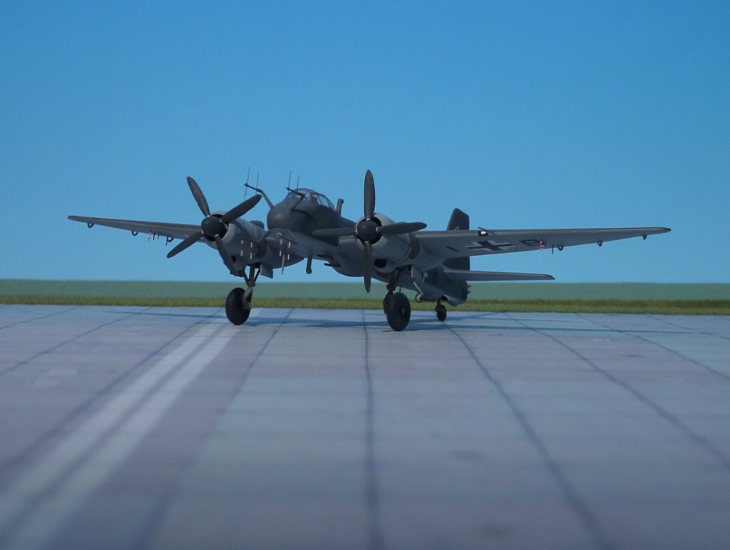
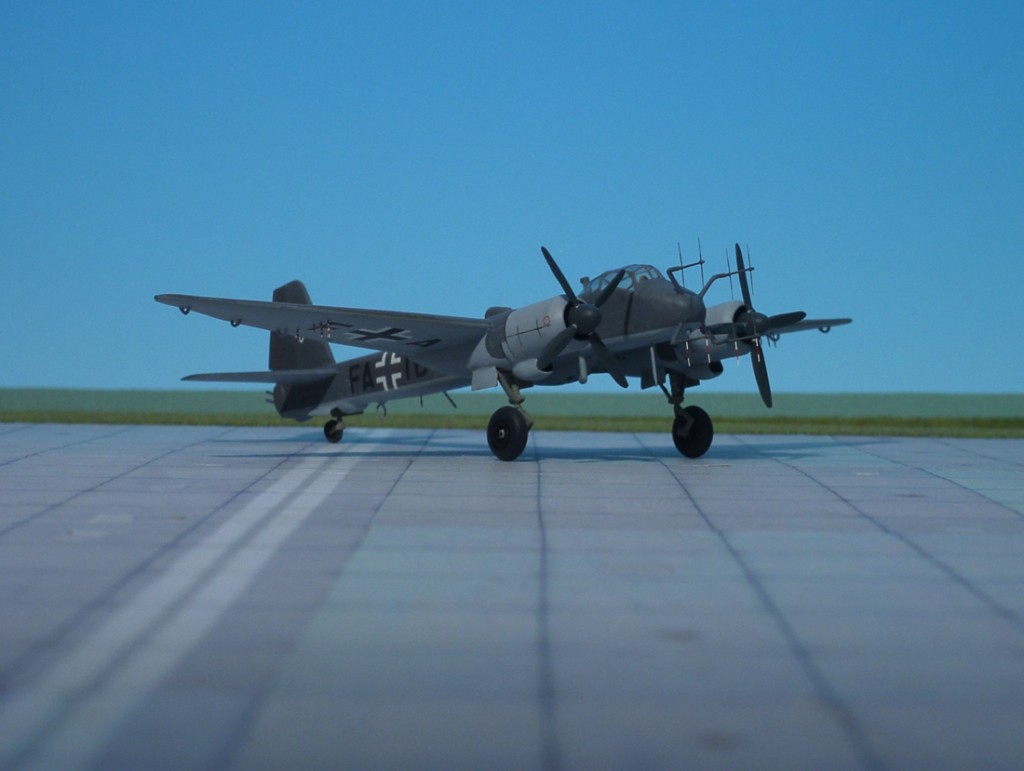
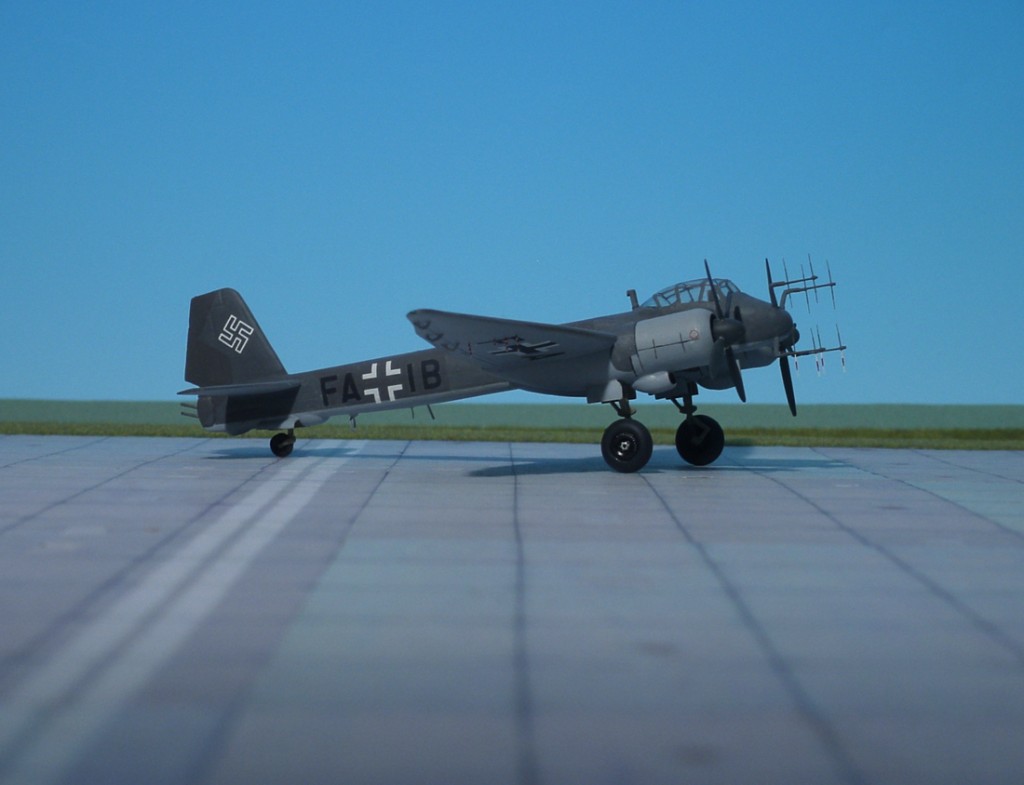
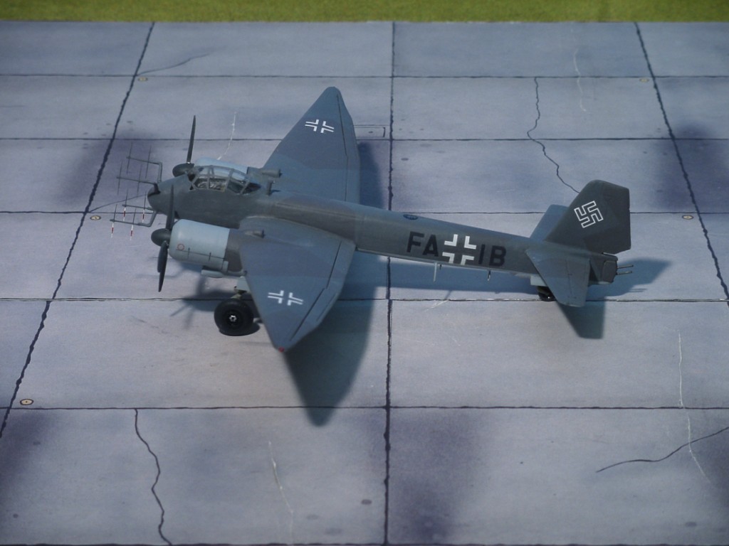
POWER PLANT: Two BMW 801TJ rated at 1,890 h.p. at 9,840 ft each
PERFORMANCE: 362 m.p.h. at 40,300 ft
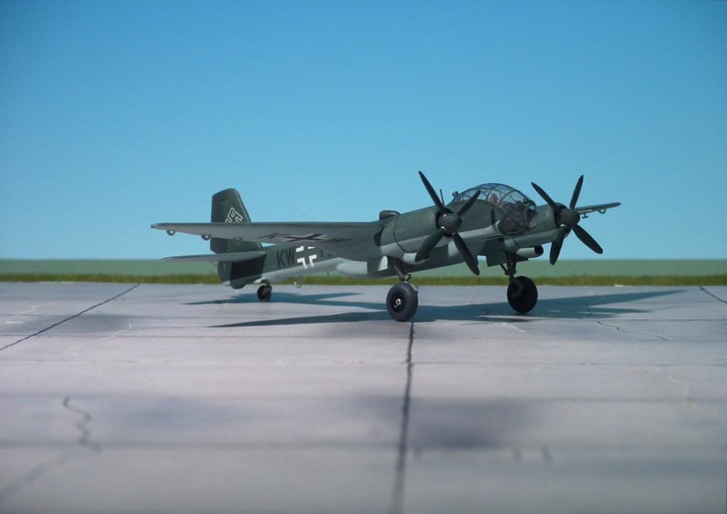
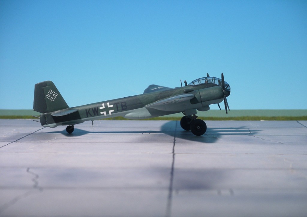
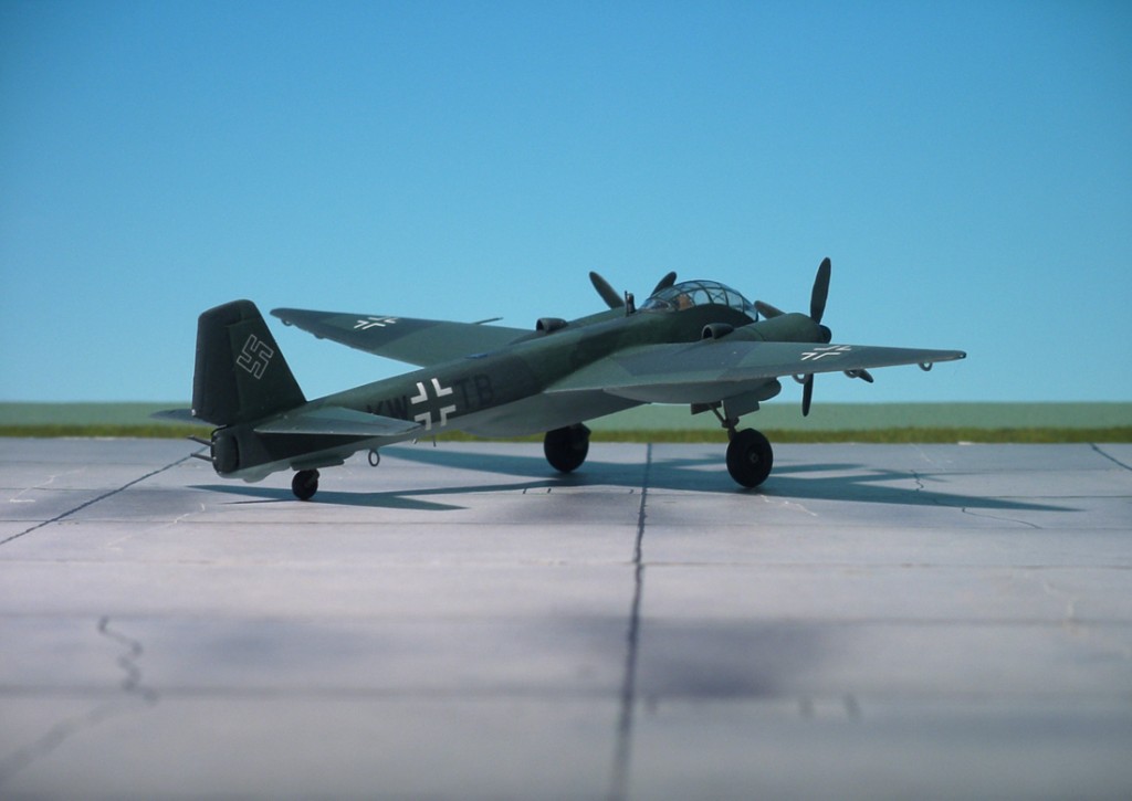
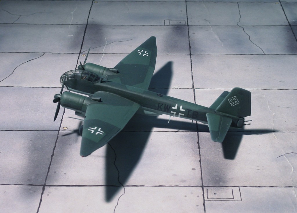
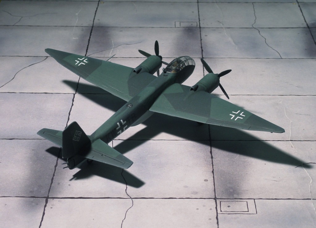
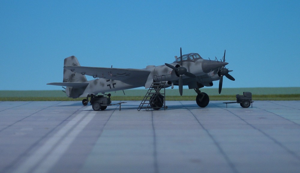
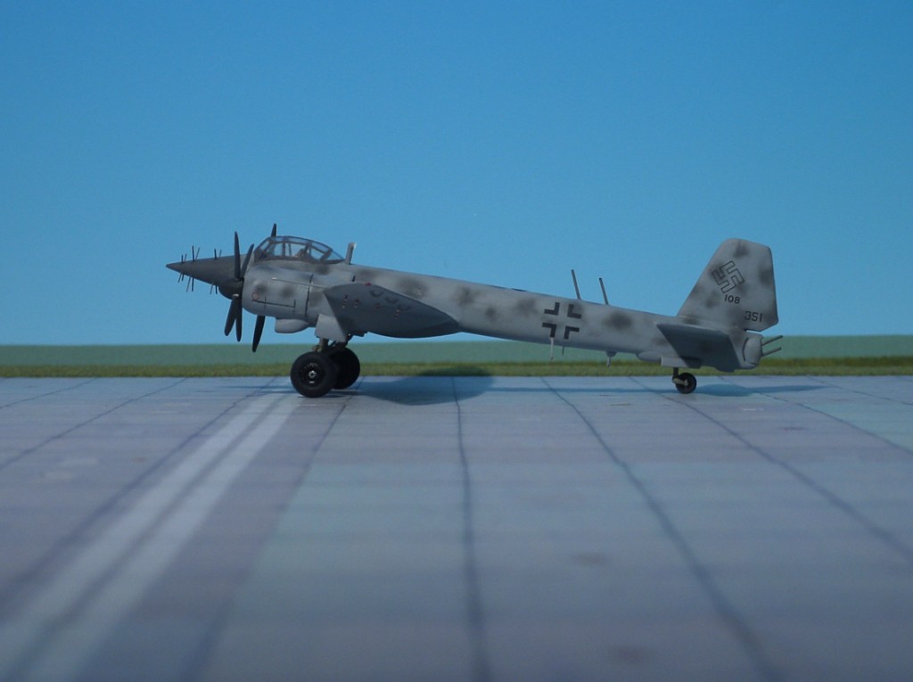
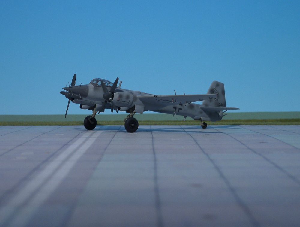
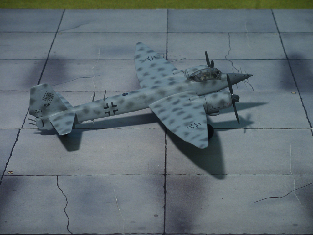
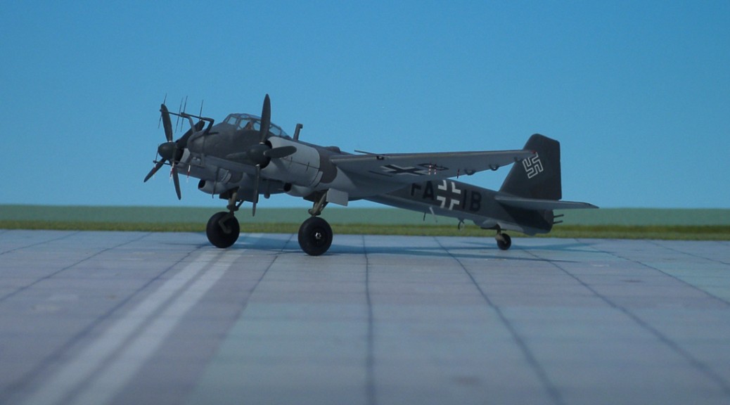
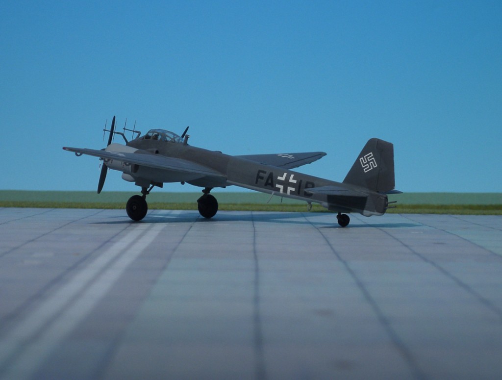
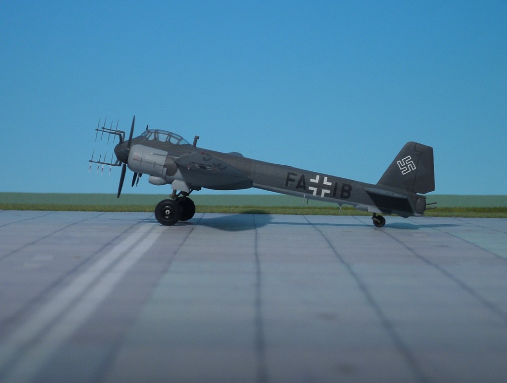
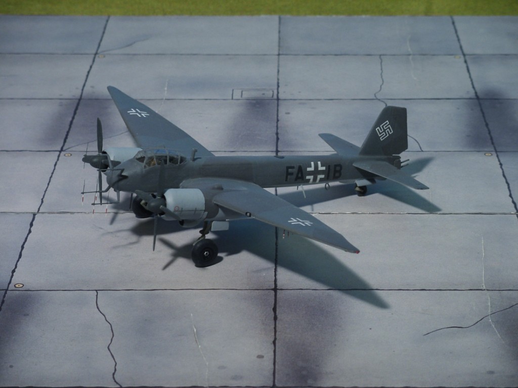
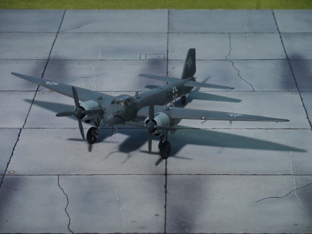
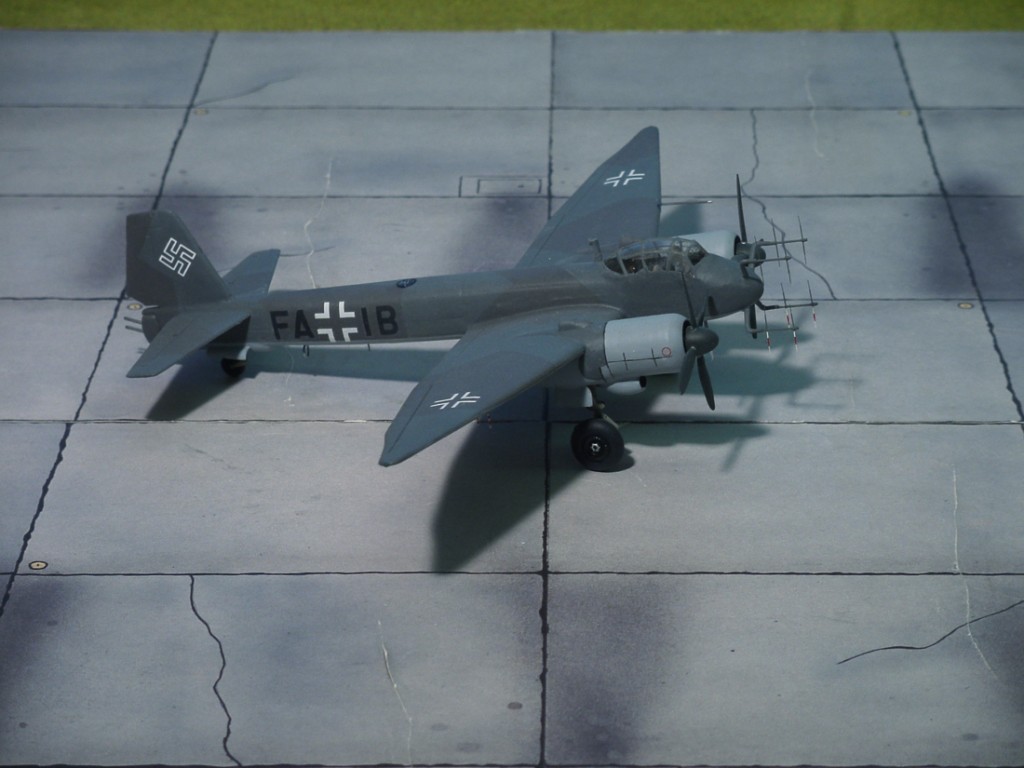
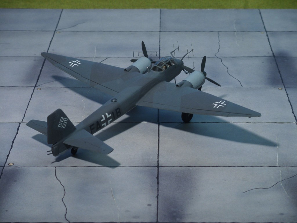
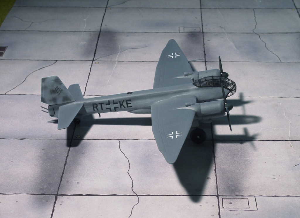
COMMENT: This prototype was converted from a Ju 188T and carried a FuG 220 “Lichtenstein SN-2” radar with “Hirschgeweih” (Stag’s Antlers) aerial array and an assymetrically mounted “Waffentropfen” (Weapon Drops) under portside mid-fuselage. This held two forward-firing 20-mm MG 151 cannons and two 30-mm MK 108 cannons. A remotely-controlled twin-gun tail barbette with MG 131Z cannons was aimed by means of a PVE 11 double periscopic sight. The code name “Störtebecker” is a reminiscent of a legendary German pirate of the 14th century
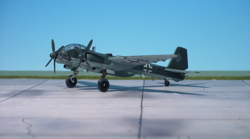
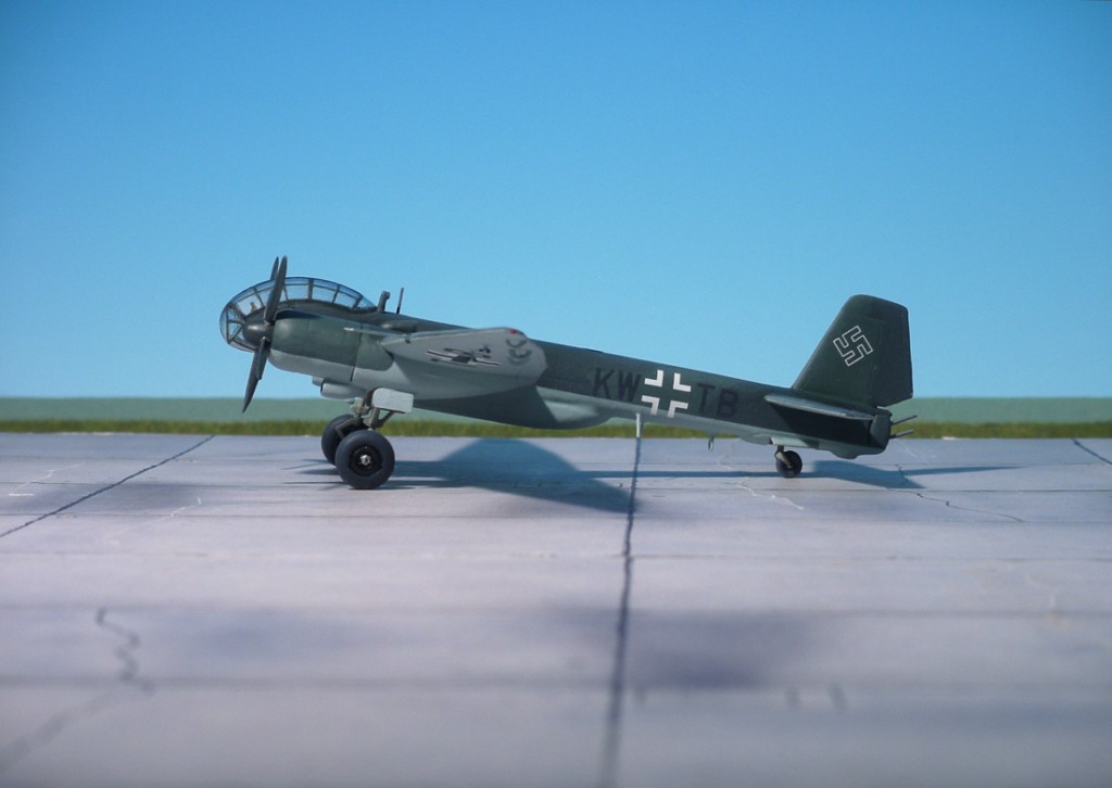
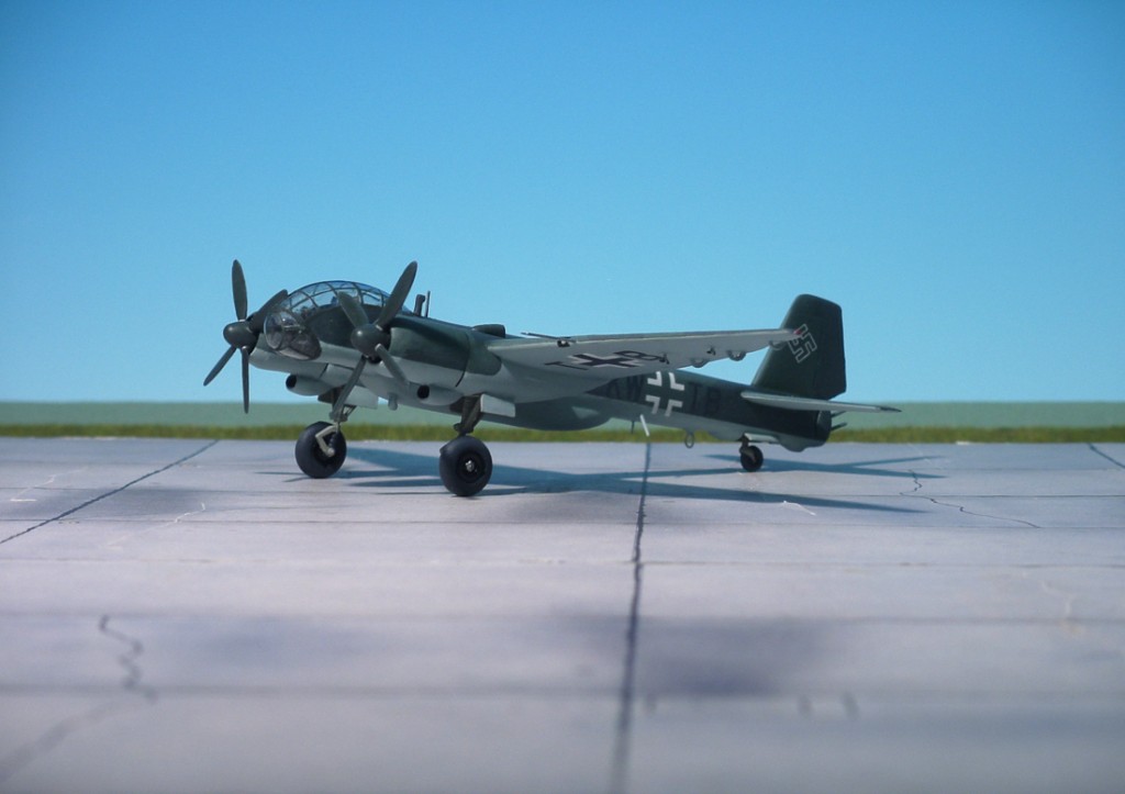
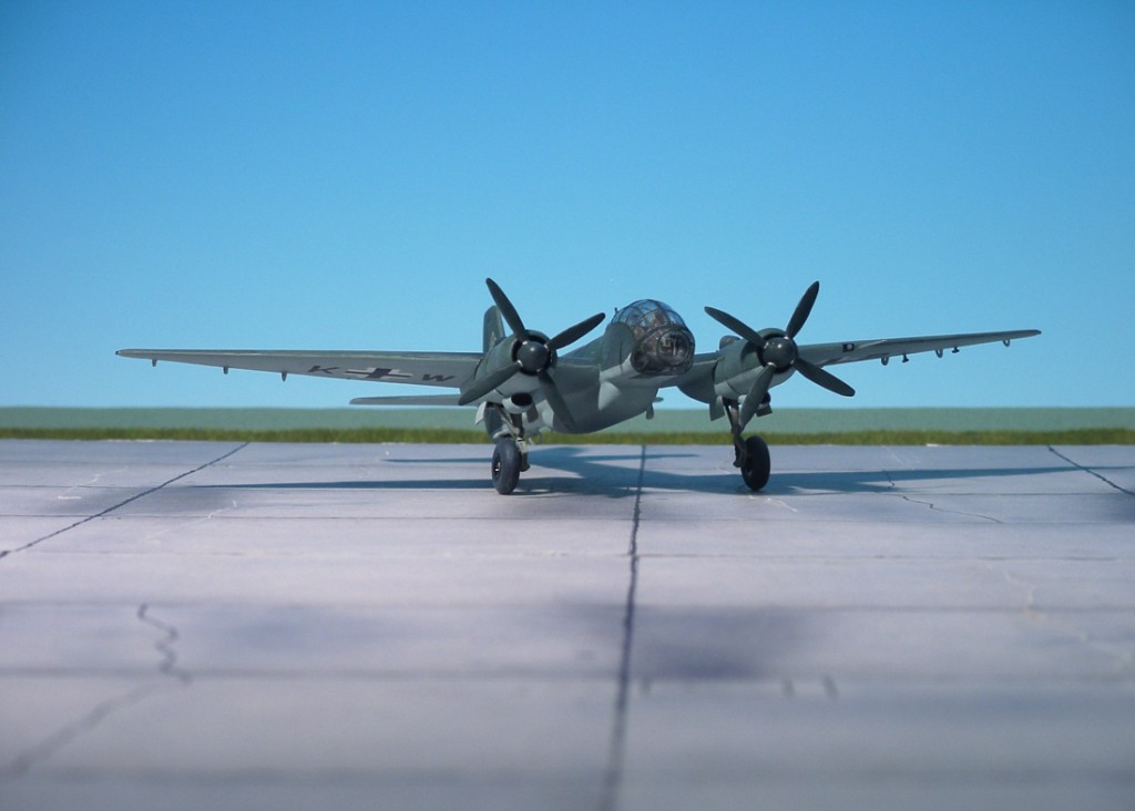
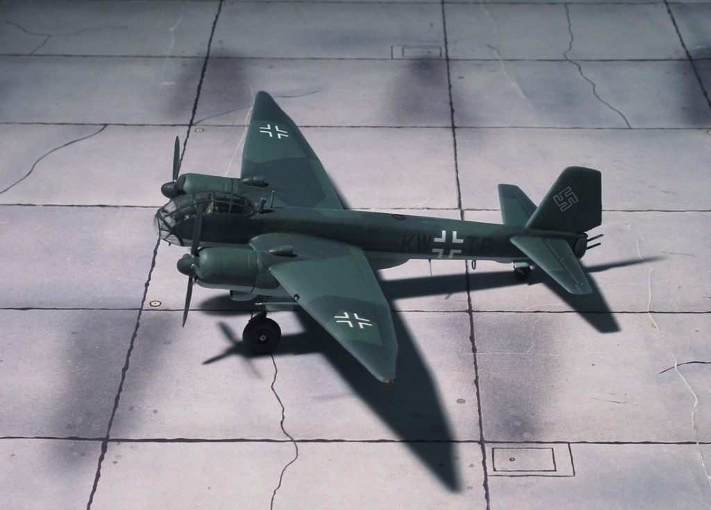
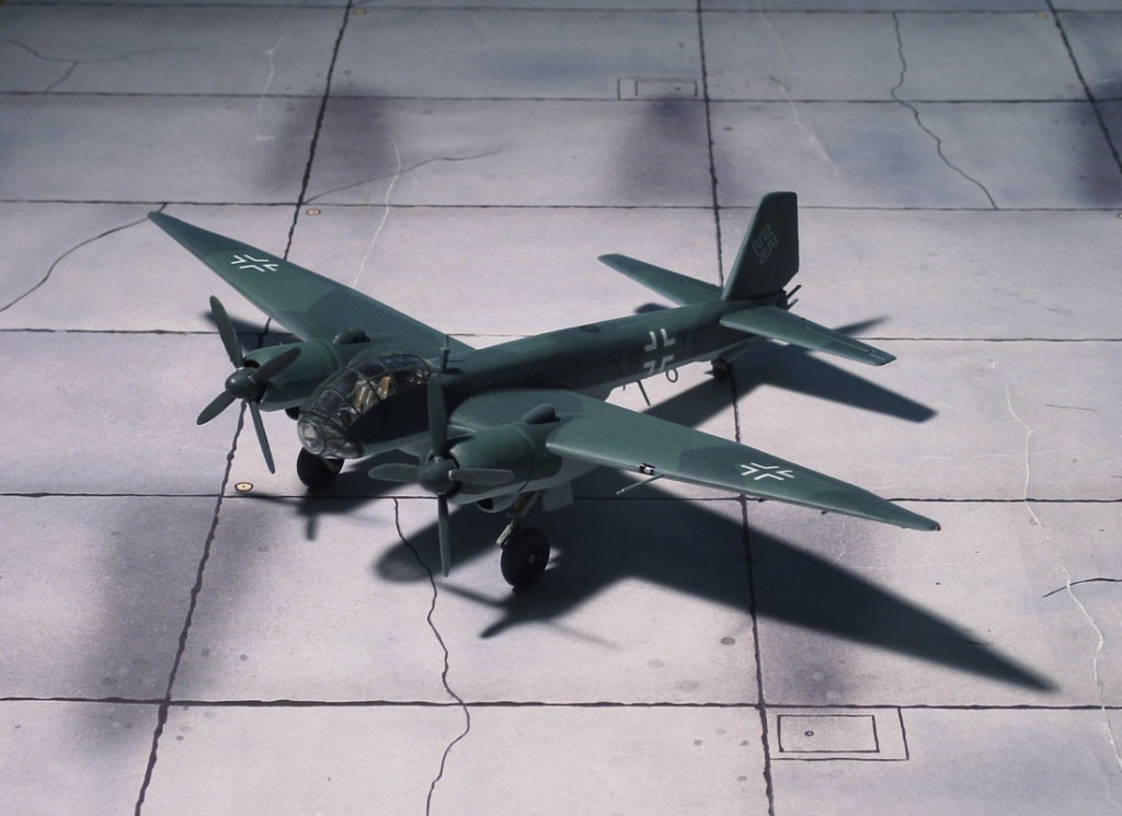
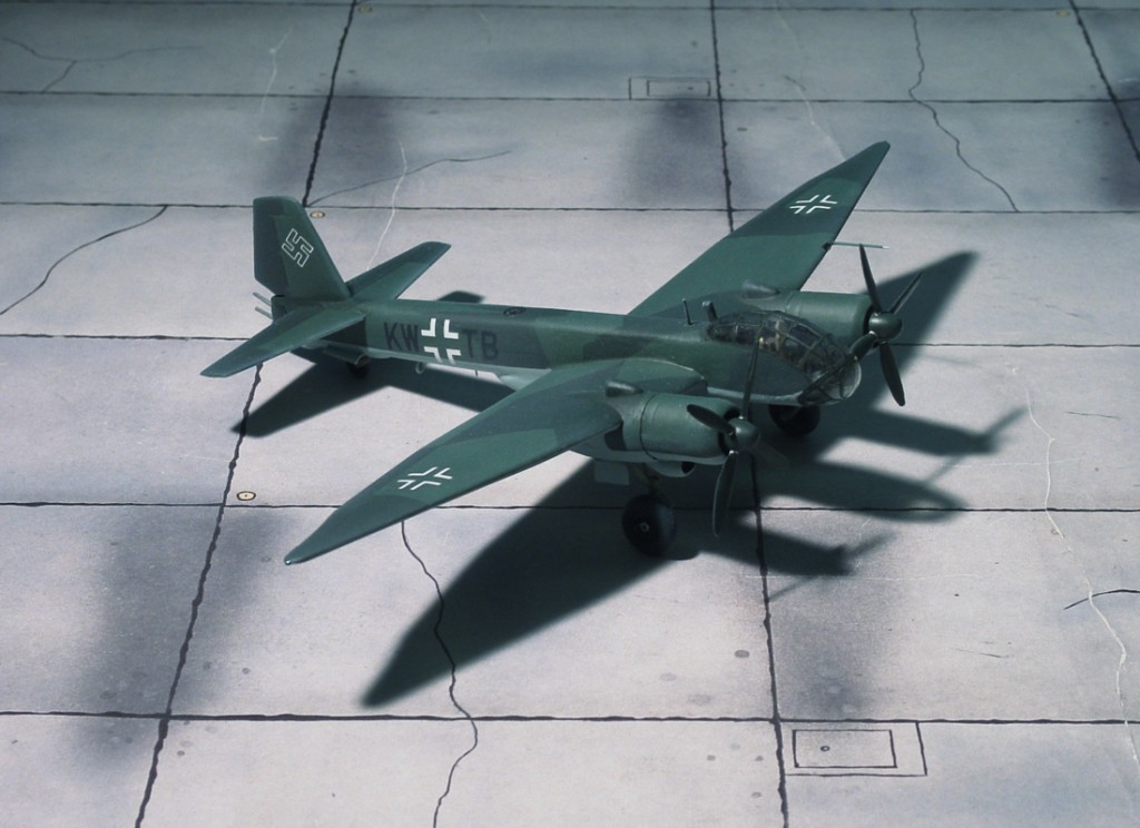
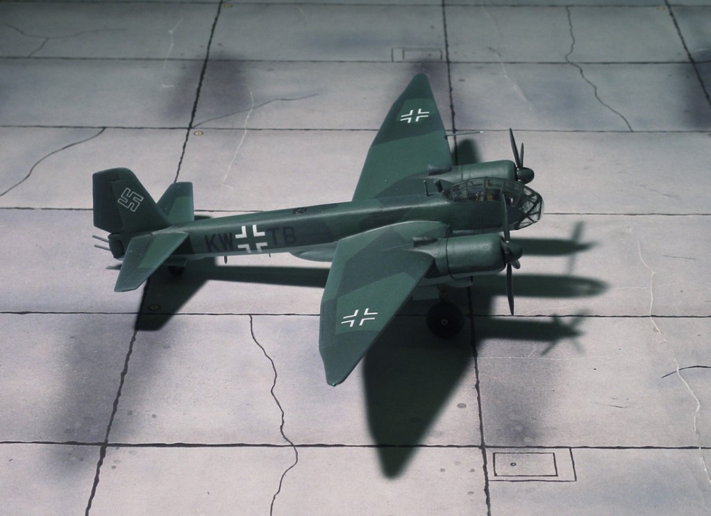
POWER PLANT: Two BMW 801TJ rated at 1,890 h.p. each
PERFORMANCE: 383 m.p.h at 40,300 ft
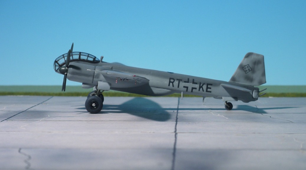
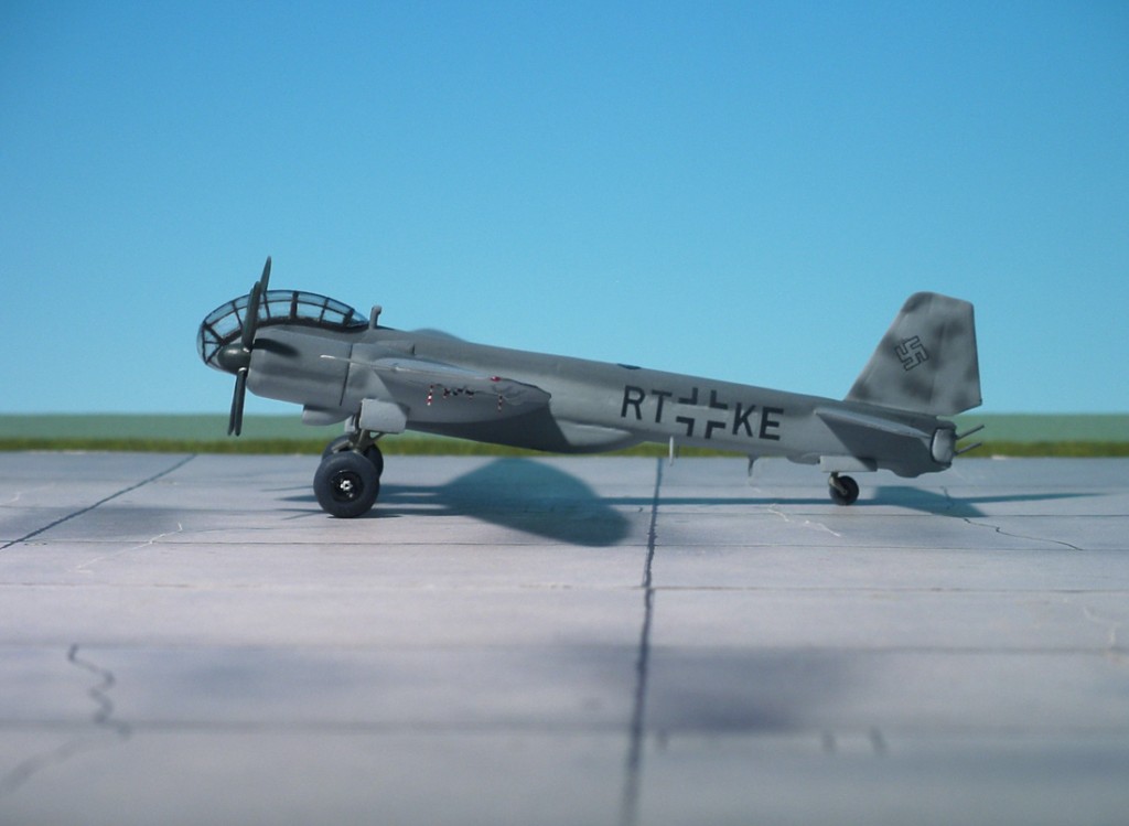
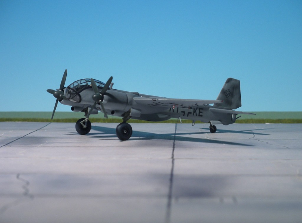
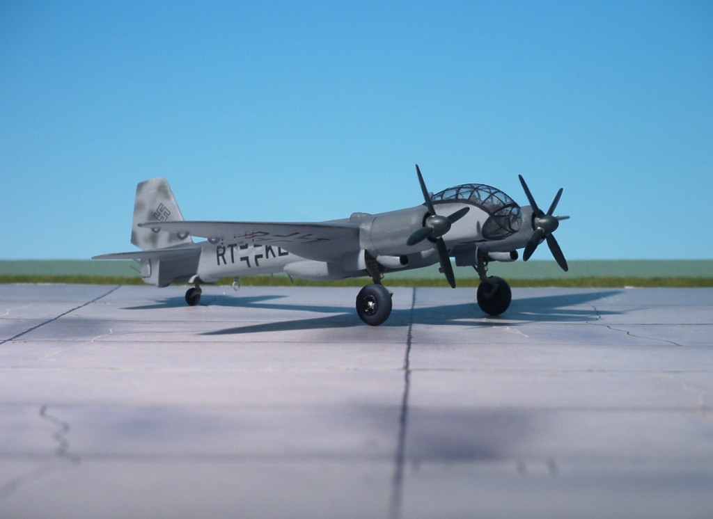
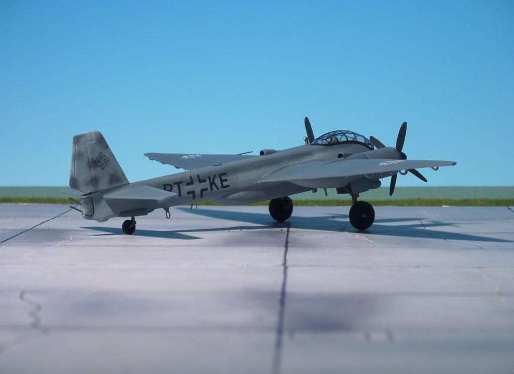
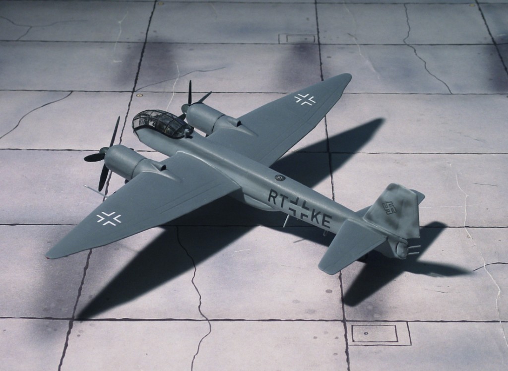
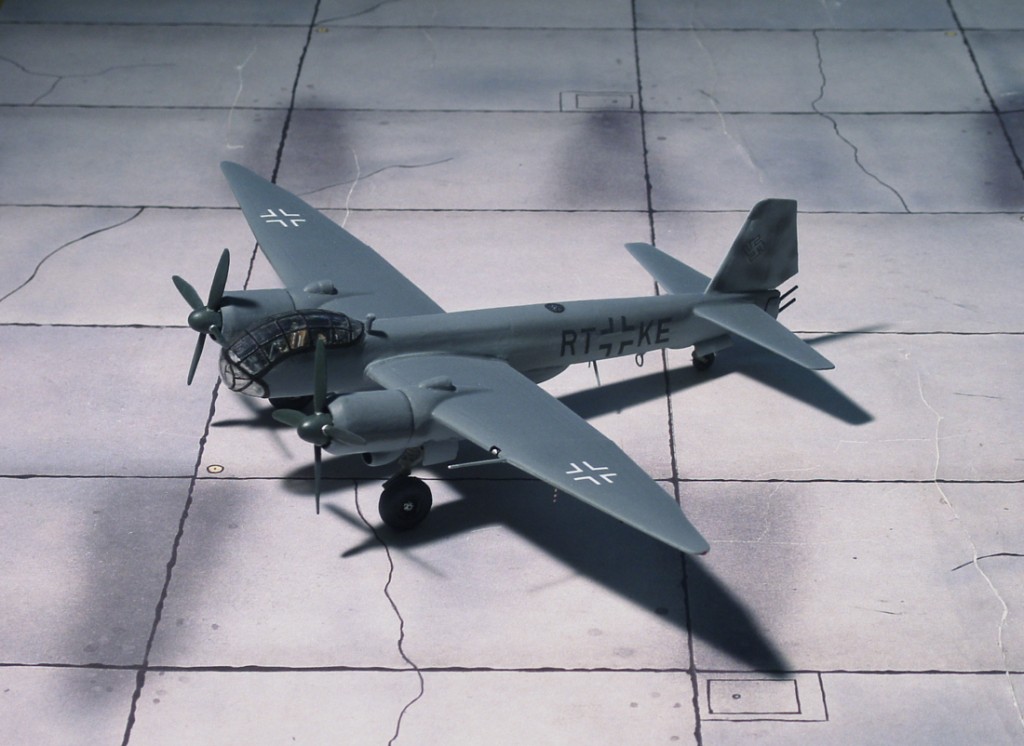
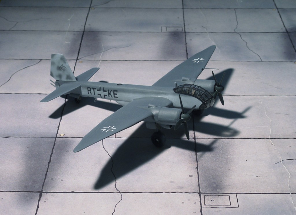
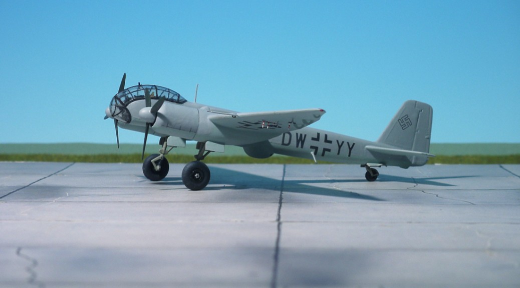
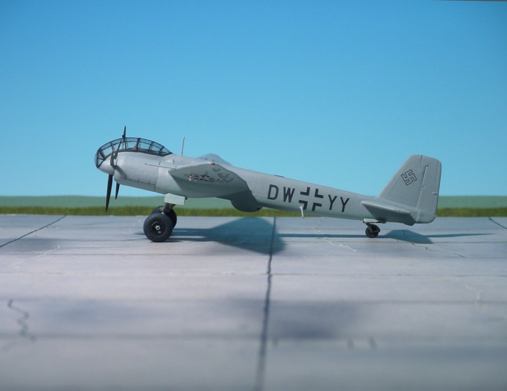
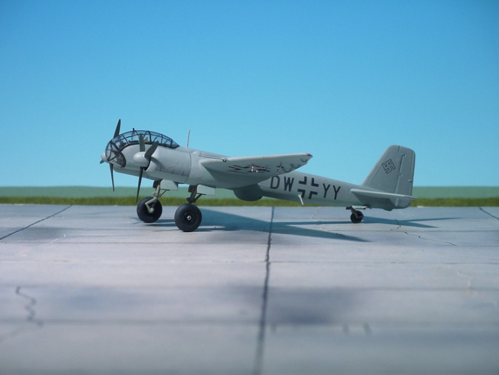
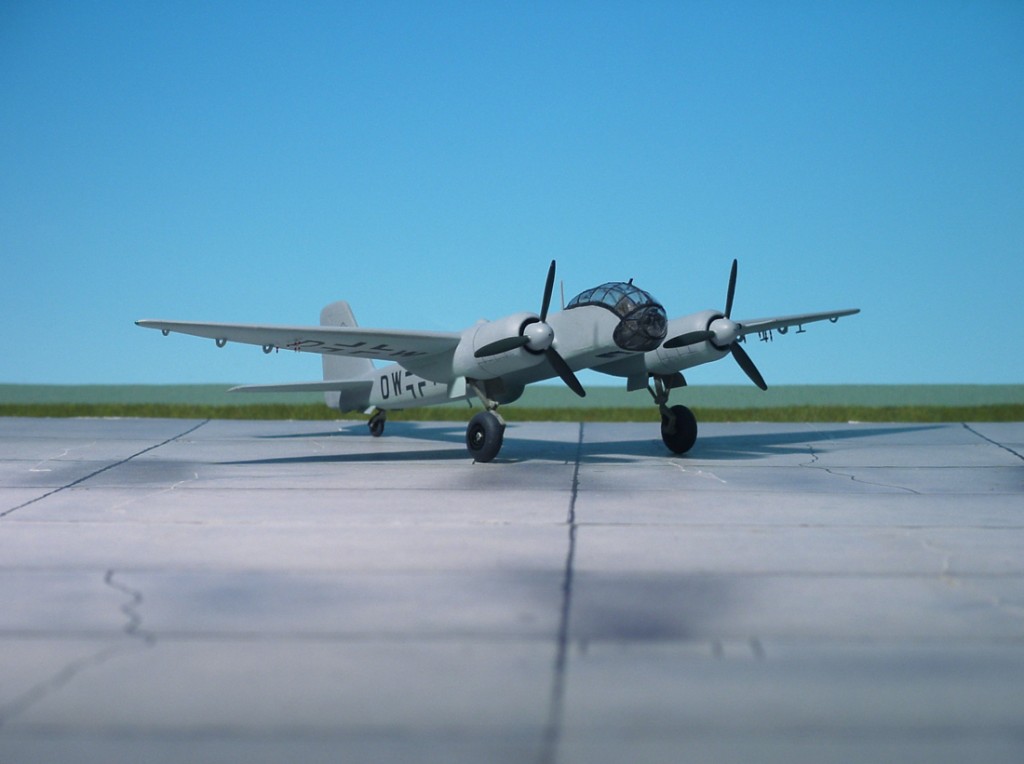
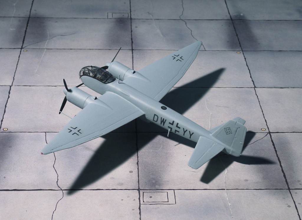
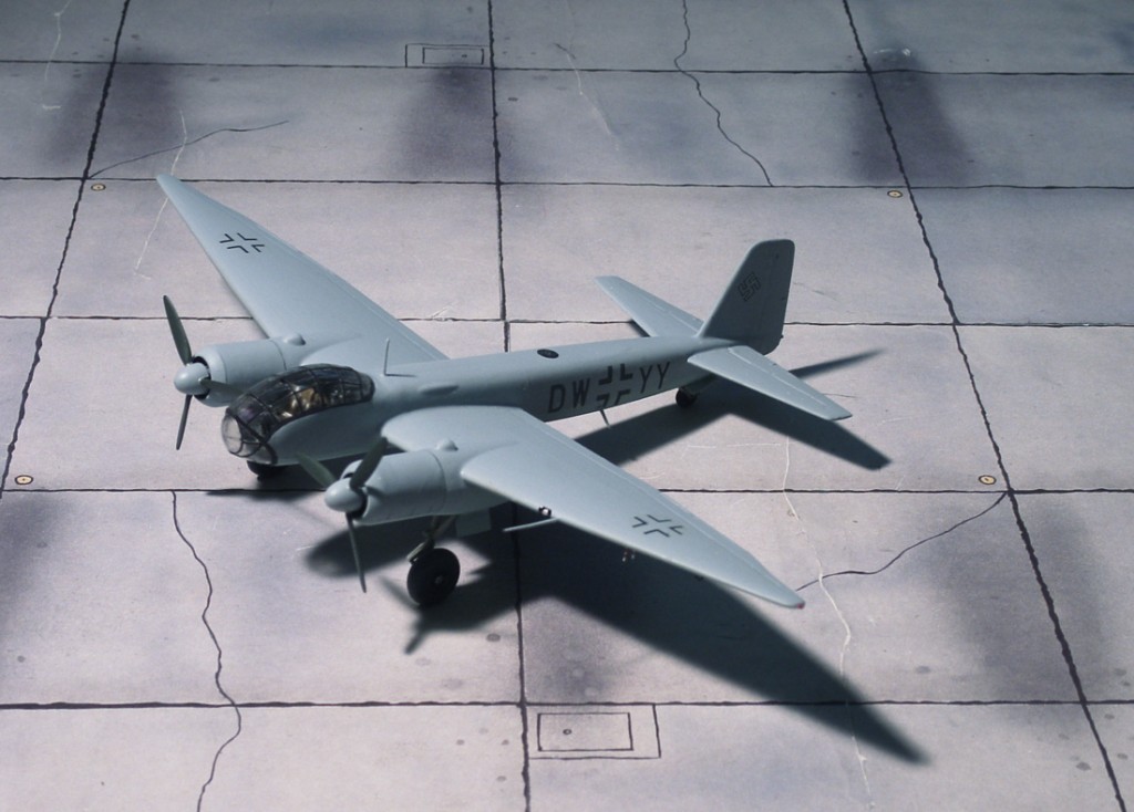
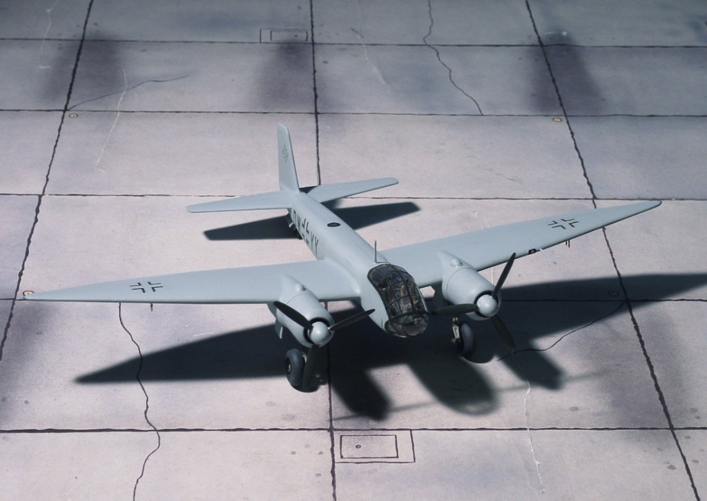
COMMENT: The production Ju 388L-1 differed from the pre-production version Ju 388L-0 in several aspects. The wooden three-blade airscrews were replaced by VDM-Dural four-bladers, a FuG 217 “Neptun” tail-warning radar was installed and the “Waffentropfen WT81Z” (Weapon Drop), housing two fixed aft-firing MG 81 machine guns, were replaced by a large wooden ventral pannier to accommodate both cameras and a jettisonable auxiliary fuel tank. A total of 47 Ju 388L reconnaissance aircraft were delivered
POWER PLANT: Two BMW 801TJ rated at 1,800 h.p. each
PERFORMANCE: 407 m.p.h. at 29,800 ft
COMMENT: This first version of the Ju 388 was derived from a Junkers Ju 188T-1. In all 10 pre-production examples were finished. These were followed by the Ju 388L-1
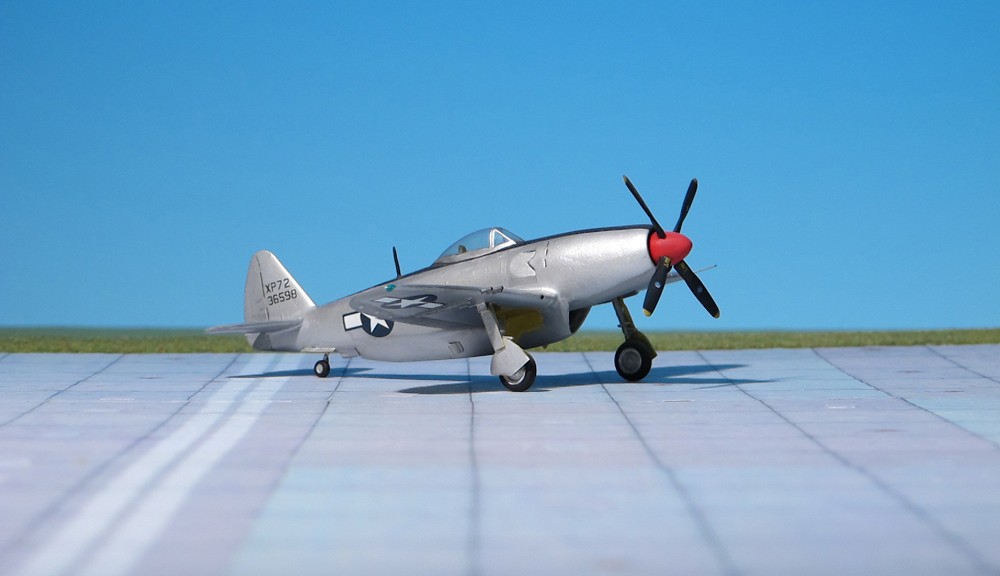
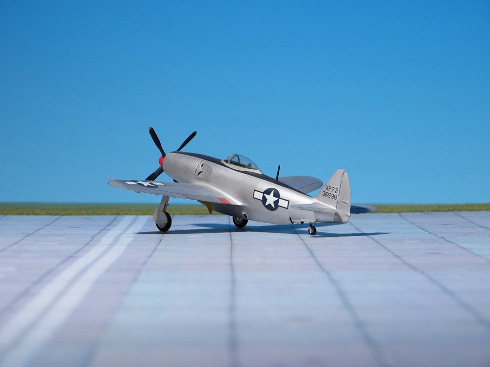
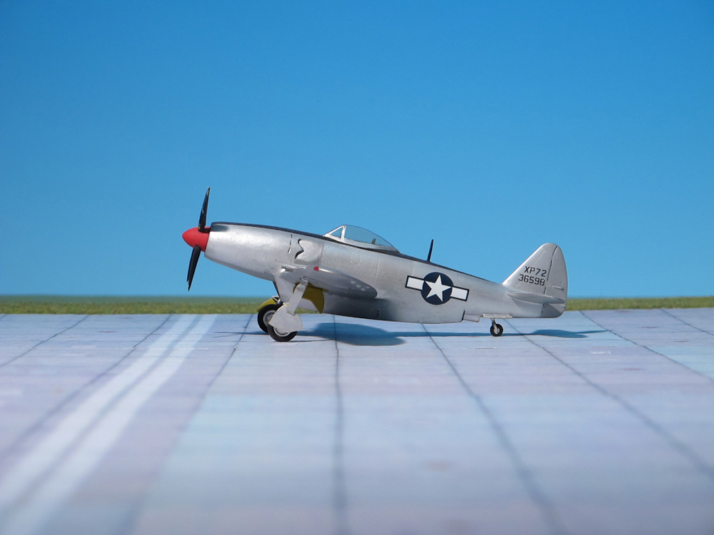
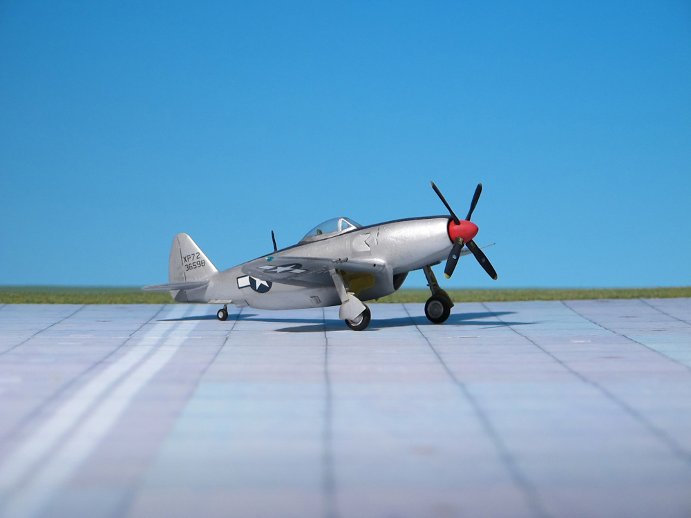
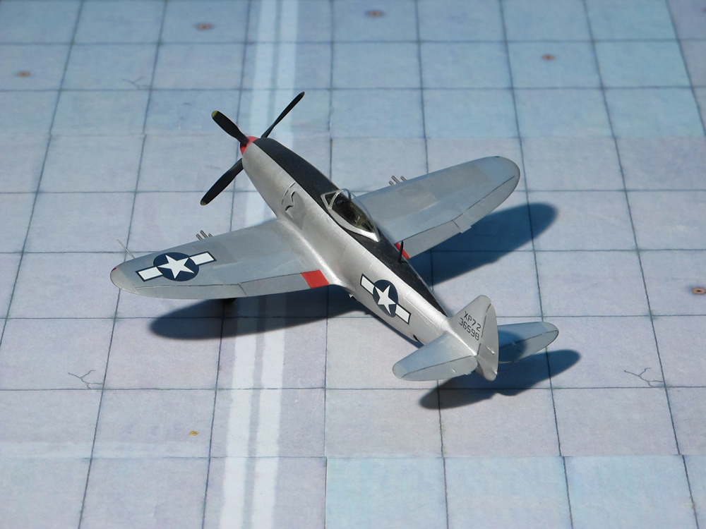
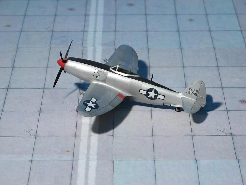
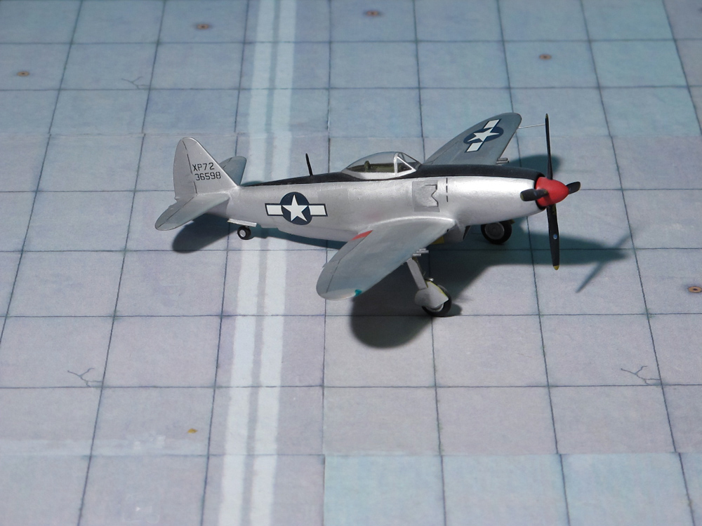
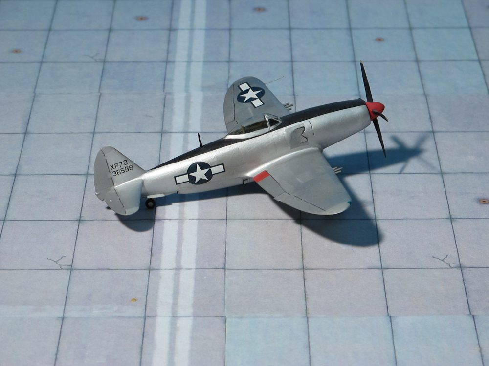
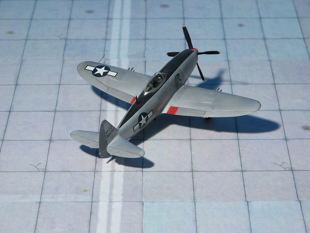
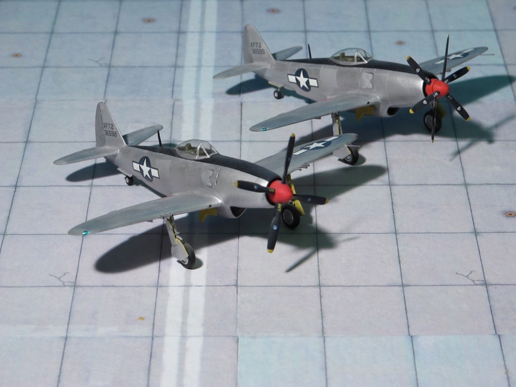
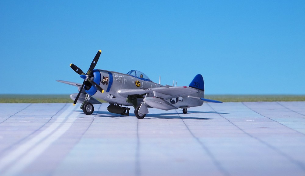
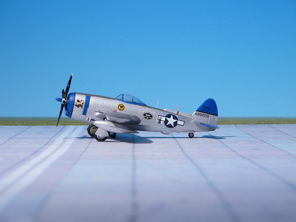
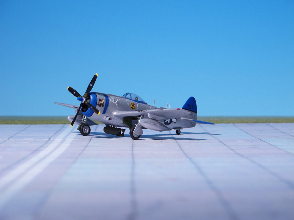
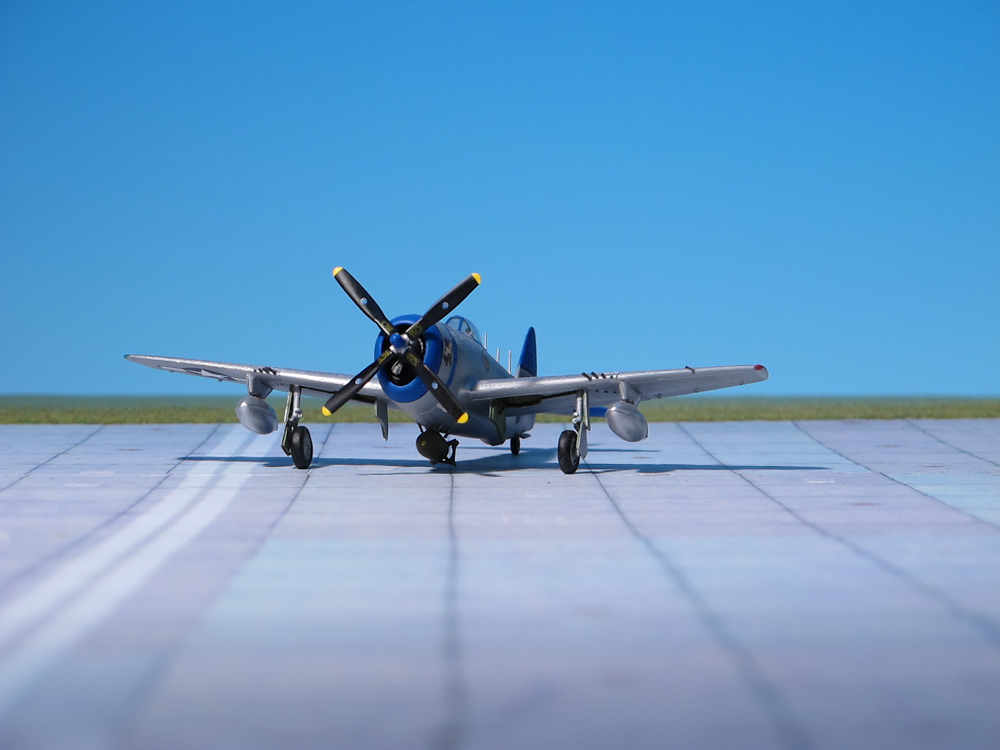
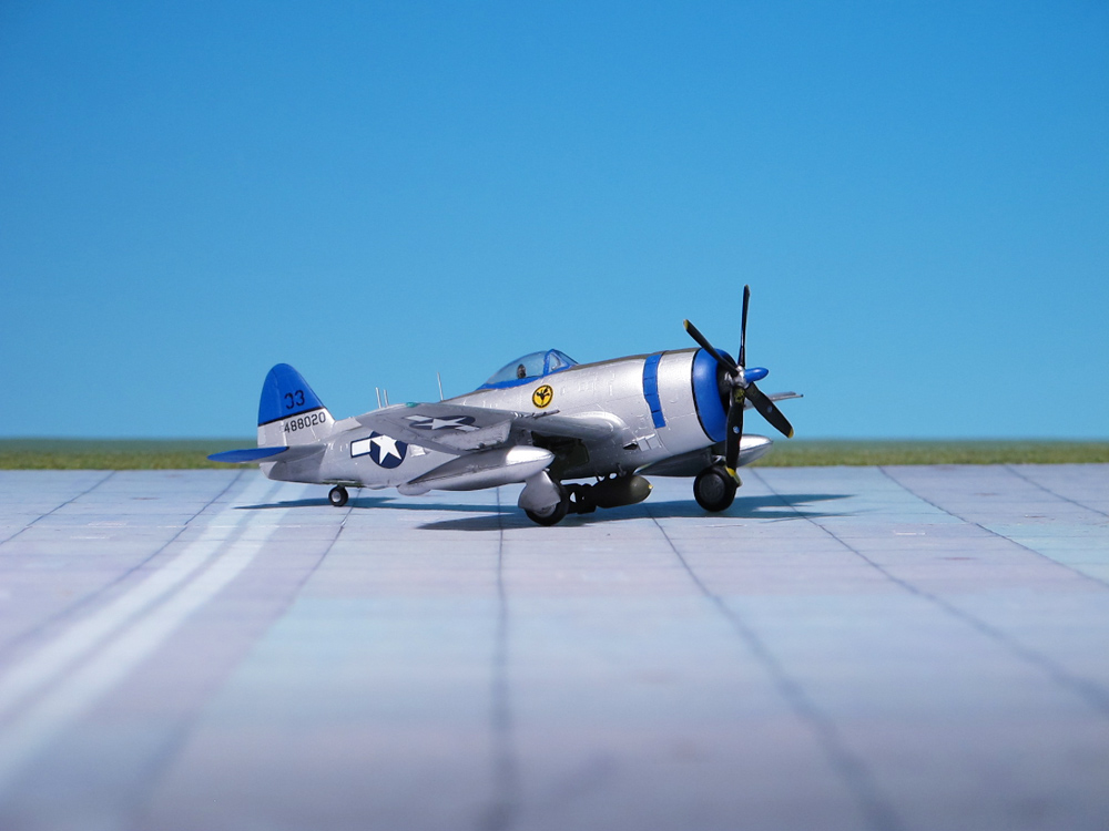
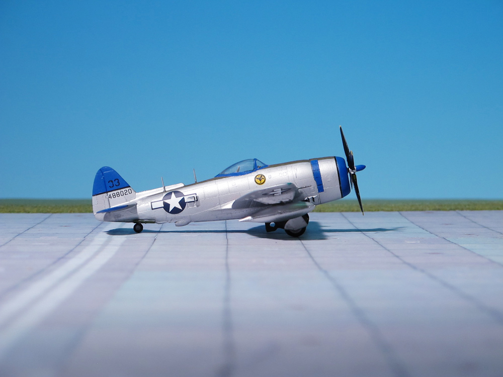
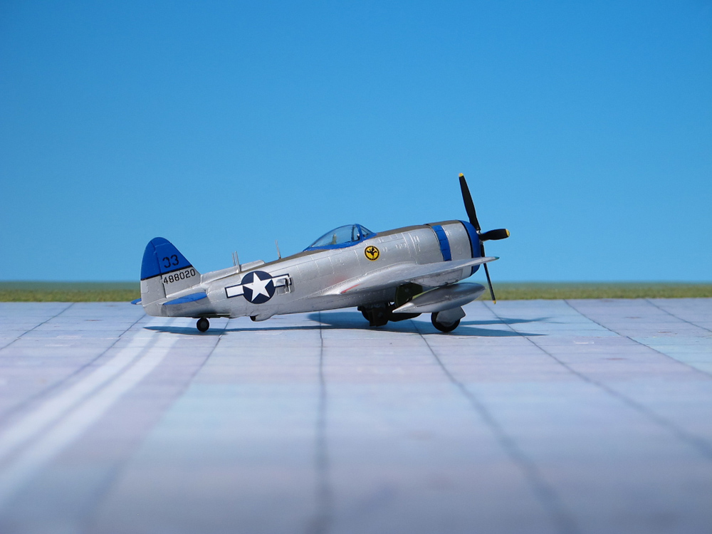
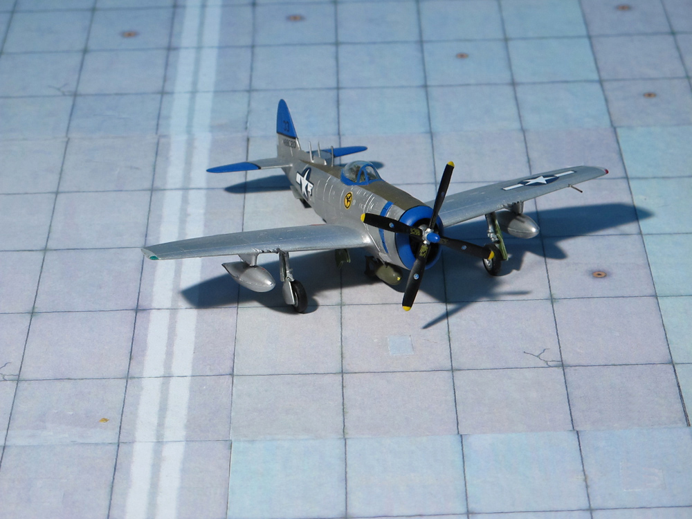
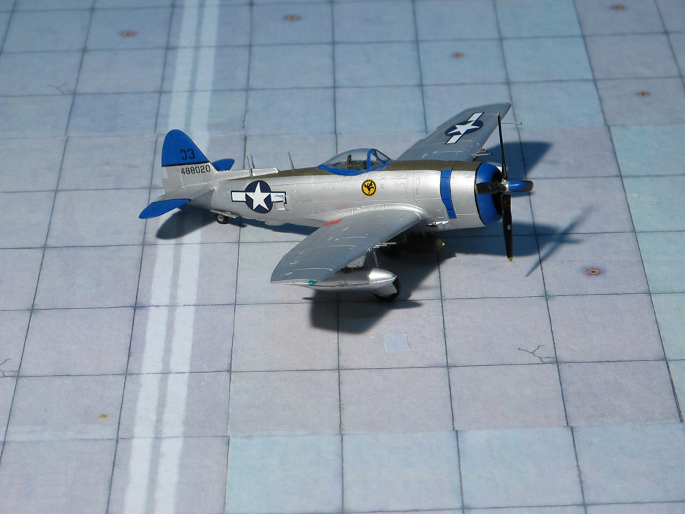
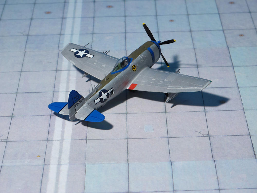
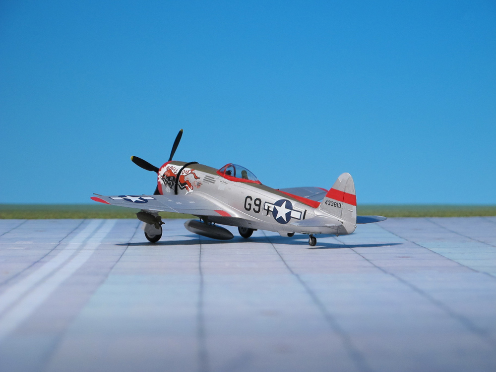
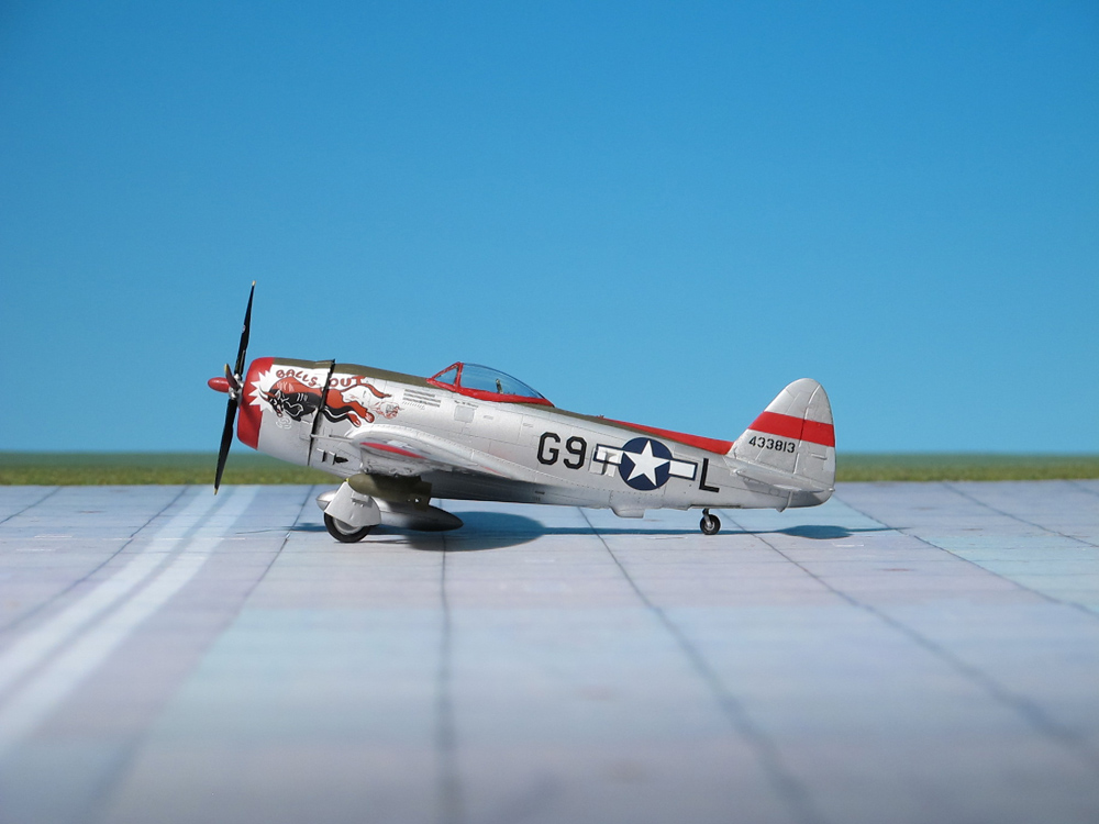
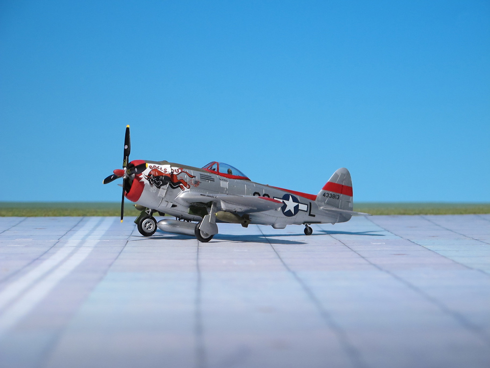
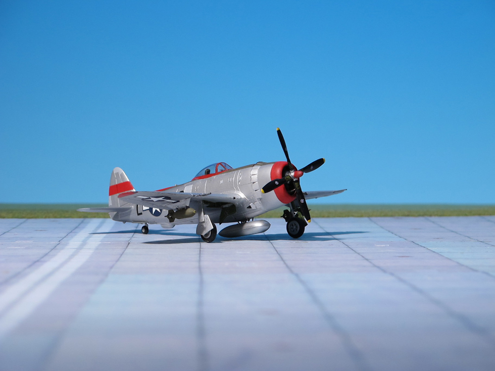
POWER PLANT: One Pratt & Whitney R-4360-13 Wasp Major engine, rated at 3,450 h.p.
PERFORMANCE: 490 m.p.h. at 25,000 ft
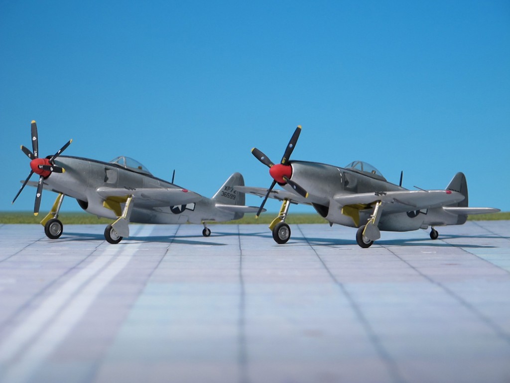
COMMENT: At the time when the famous Republic P-47 “Thunderbolt” was not ordered by USAAF for mass production, Republic worked on a completely different fighter, the Republic XP-69. But in 1943 this project was cancelled in favour of a less radical design, the XP-72, and two prototypes were ordered. The first flew on 2 February 1944 with a four bladed propeller; the second XP-72 prototype had Aero Product contra props. An initial production contract for 100 aircrafts was ordered, which were foreseen as being useful for combat with V-1s, being launched in Europe at that time. But the need for long-range escort fighters declined, so the order was cancelled
Republic XP-72
Republic XP-72
Republic XP-72
Republic XP-72
Republic XP-72
Republic XP-72 and Republic XP-72 with contraprops
Republic XP-72
Republic XP-72
Republic XP-72
Republic XP-72
Republic XP-72
Republic XP-72 and Republic XP-72 with contraprops
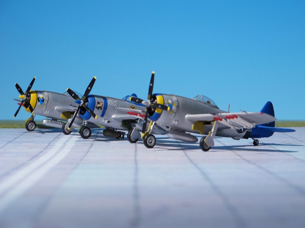
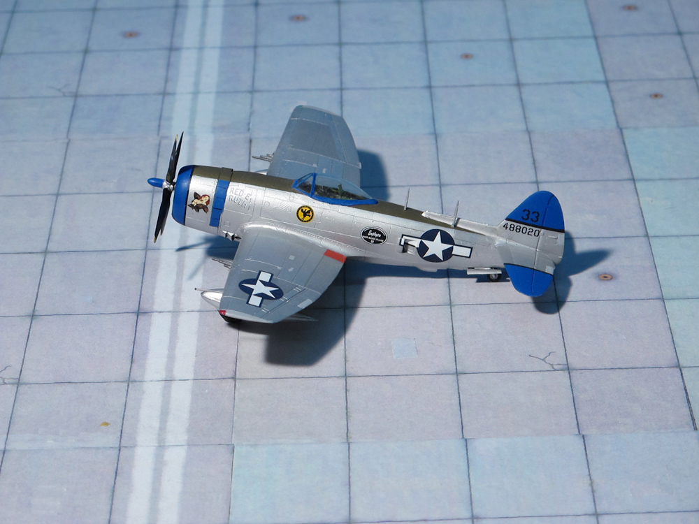
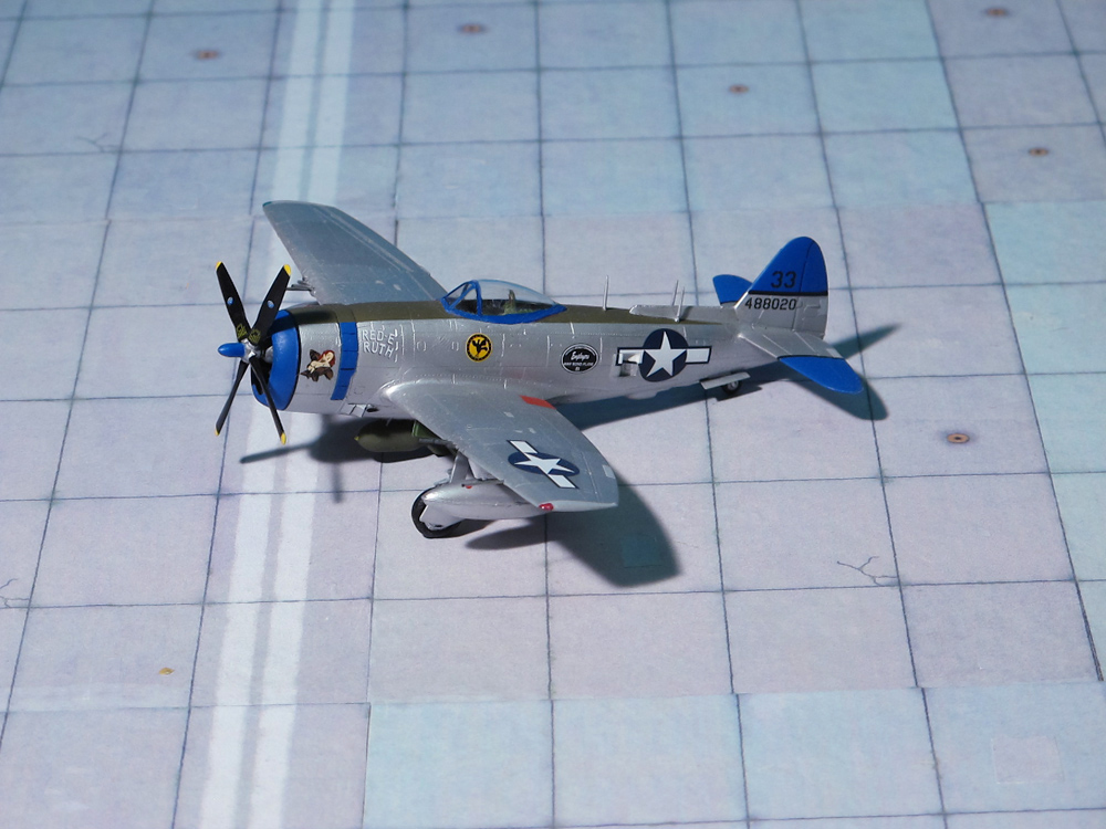
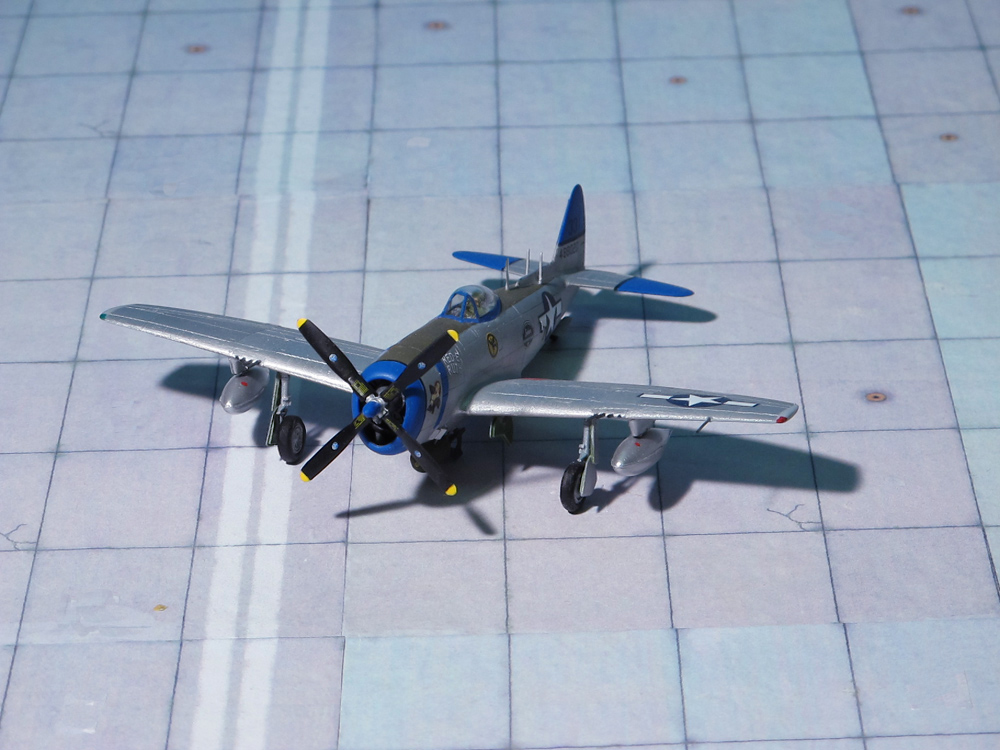
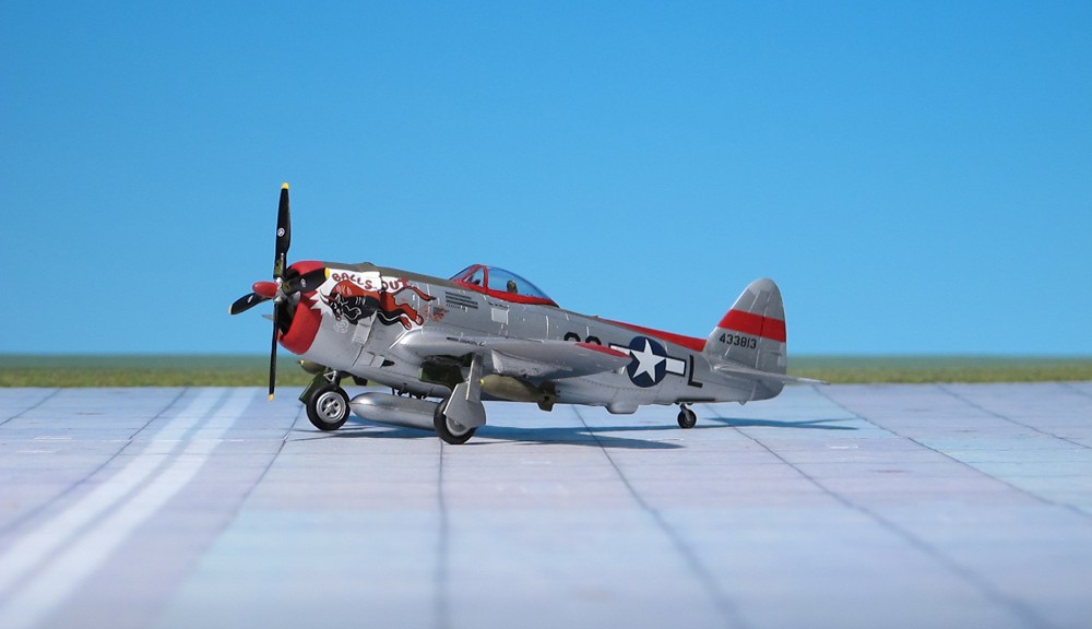
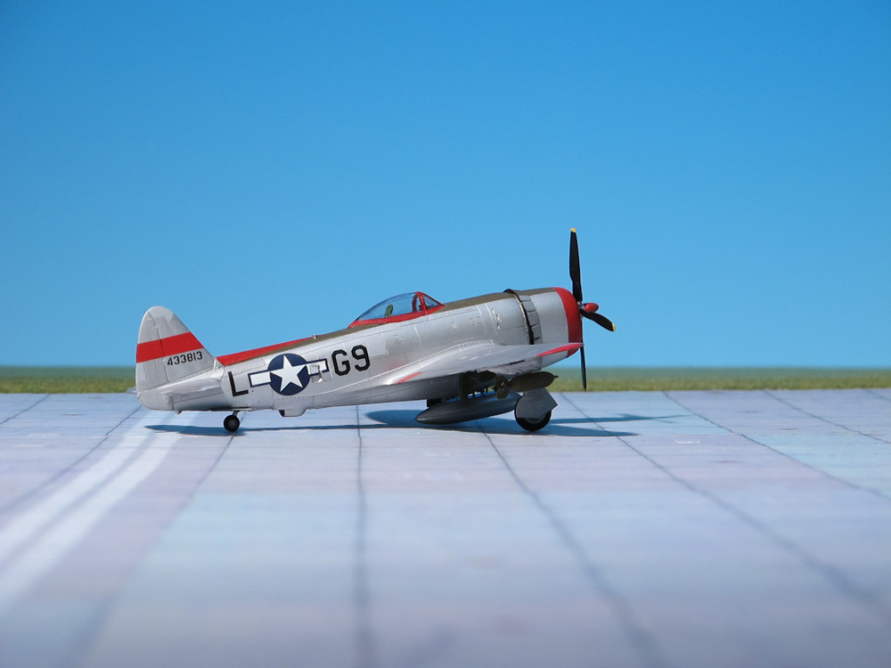
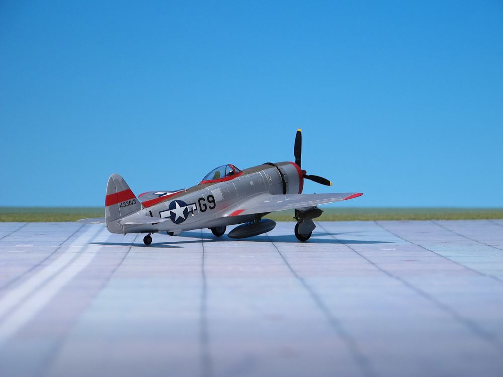
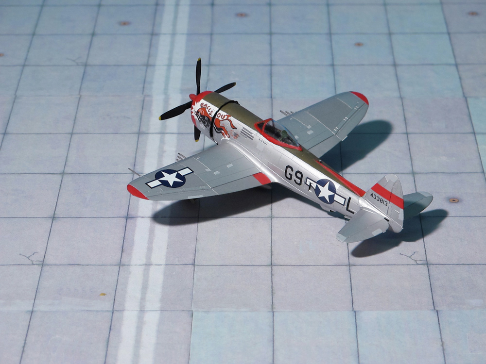
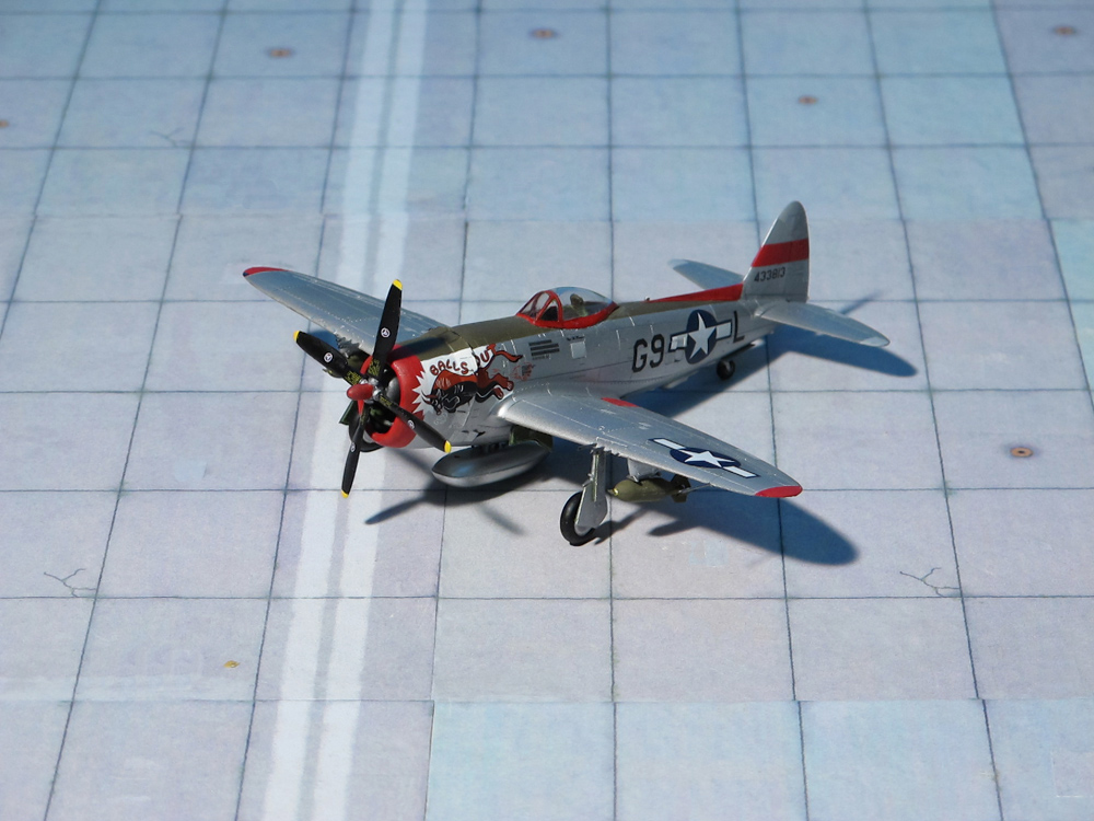
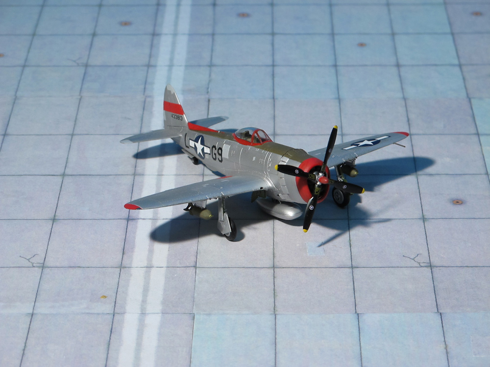
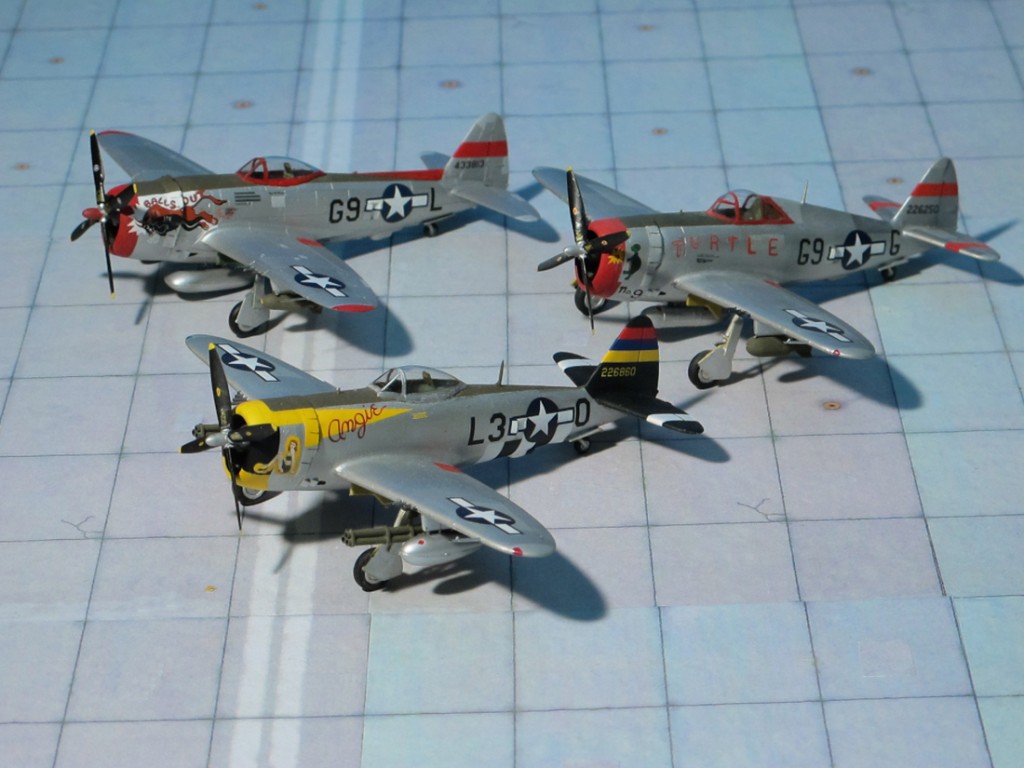
POWER PLANT: Pratt & Whitney R-2800-77 ‘Double Wasp’ radial engine, rated at 2,800 hp
PERFORMANCE: 460 mph at 30,000 ft
COMMENT: The Republic P-47N was the last Thunderbolt variant to be produced. It was designed as an escort fighter for the Boeing B-29 Superfortress bombers flying raids on the Japanese home islands. Increased internal fuel capacity and drop tanks had done much to extend the Thunderbolt’s range during its evolution, and the only other way to expand the fuel capacity was to put fuel tanks into the wings. Thus, a new wing was designed with two 50 U.S. gal fuel tanks. The redesign proved successful in extending range to about 2,000 miles, and the squared-off wingtips improved the roll rate. The P-47N entered mass production with the uprated R-2800-57 engine, with a total of 1,816 built. The very last Thunderbolt to be built, a P-47N-25, rolled off the production line in October 1945. Thousands more had been on order, but production was halted with the end of the World War II in August 1945.
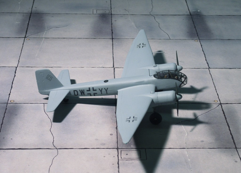
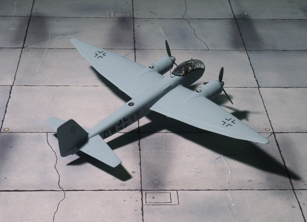
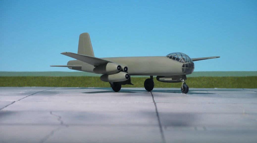
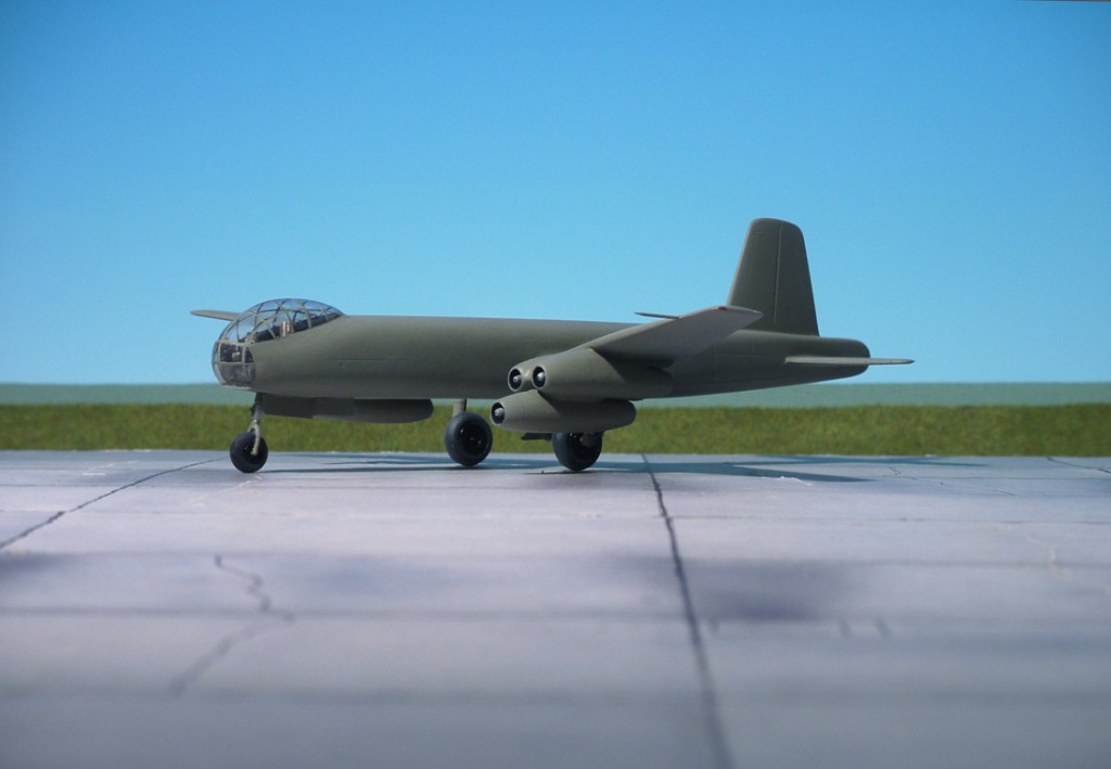
POWER PLANT: Four Junkers Jumo 004B-1 turbojet engines, rated at 950 kp each
PERFORMANCE: 347 mph at 19,685 ft
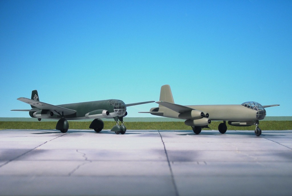
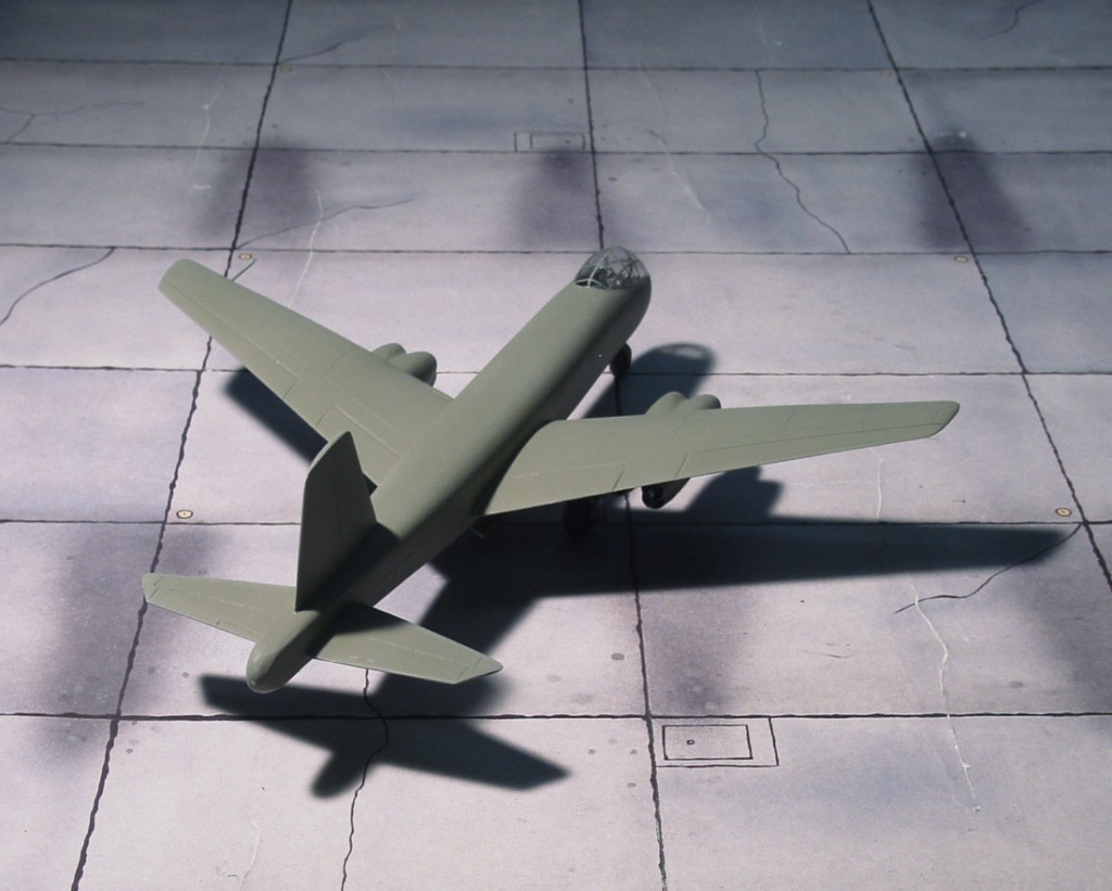
COMMENT: The Ju 287 was intended to provide the Luftwaffe (German Air Force) with a bomber that could avoid interception by outrunning enemy fighters. The swept-forward wing was suggested as a way of providing extra lift at low airspeeds, necessary because of the poor responsiveness of early turbojet engines at the vulnerable times of takeoff and landing. A further structural advantage of the forward-swept wing was that it would allow for a single massive weapons bay forward of the main wing spar. The first prototype was intended to evaluate the concept, and was assembled from the fuselage of a Heinkel He 177, the tail of a Junkers Ju 388, main undercarriage from a Junkers Ju 352, and nose wheels taken from crashed Consolidated B-24 ‘Liberator’, all of which were fixed to lower weight and complexity, and equipped with spats to reduce drag. Two of the Junkers Jumo 004 turbojet engines were hung in nacelles (pods) under the wings, with the other two mounted in nacelles added to the sides of the forward fuselage. Flight tests began on 16 August 1944, with the aircraft displaying extremely good handling characteristics, as well as revealing some of the problems of the forward-swept wing under some flight conditions. The most notable of these drawbacks was ‘wing warping’, or excessive inflight flexing of the main spar and wing assembly. Tests suggested that the warping problem would be eliminated by concentrating greater engine mass under the wings. This technical improvement would be incorporated in the subsequent prototypes. The production version of the Junkers Ju 287 was intended to be powered by four Heinkel-Hirth HeS 011 engines, but because of the development problems experienced with that engine, the BMW 003 was selected in its place. The second and third prototypes, V2 and V3, were to have employed six of these engines, in a triple cluster under each wing. Both were to feature the all-new fuselage and tail design intended for the production bomber, the Ju 287A-1. V3 was to have served as the pre-production template, carrying defensive armament, a pressurized cockpit and full operational equipment.
Work on the Ju 287 program, along with all other pending German bomber projects (including Junkers’ other ongoing heavy bomber design, the piston-engined Junkers Ju 488 came to a halt in July 1944, but Junkers was allowed to go forward with the flight testing regime on the V1 prototype. The wing section for the V2 had been completed by that time. Seventeen test flights were undertaken in total, which passed without notable incident. Minor problems, however, did arise with the turbojet engines and the RATO booster units, which proved to be unreliable over sustained periods. This initial test phase was designed purely to assess the low-speed handling qualities of the forward-swept wing, but despite this the V1 was dived at full jet power on at least. After the seventeenth and last flight in late autumn of 1944, the V1 was placed in storage and the Ju 287 program came to what was then believed to be its end. However, in March 1945, for reasons that are not entirely clear, the 287 program was restarted, with the RLM issuing a requirement for mass production of the jet bomber (100 airframes a month) as soon as possible. The V1 prototype was taken out of storage and transferred to the Luftwaffe evaluation center at Rechlin, but was destroyed in an Allied bombing raid before it could take to the air again. Construction on the V2 and V3 prototypes was resumed at the Junkers factory near Leipzig, where they were captured by Soviet troops and brought to the Soviet Union including the Junkers design team. Redesigned in its original work number EF 131 the V3 aircraft flew for the first time in 1947 (Ref.: 24).
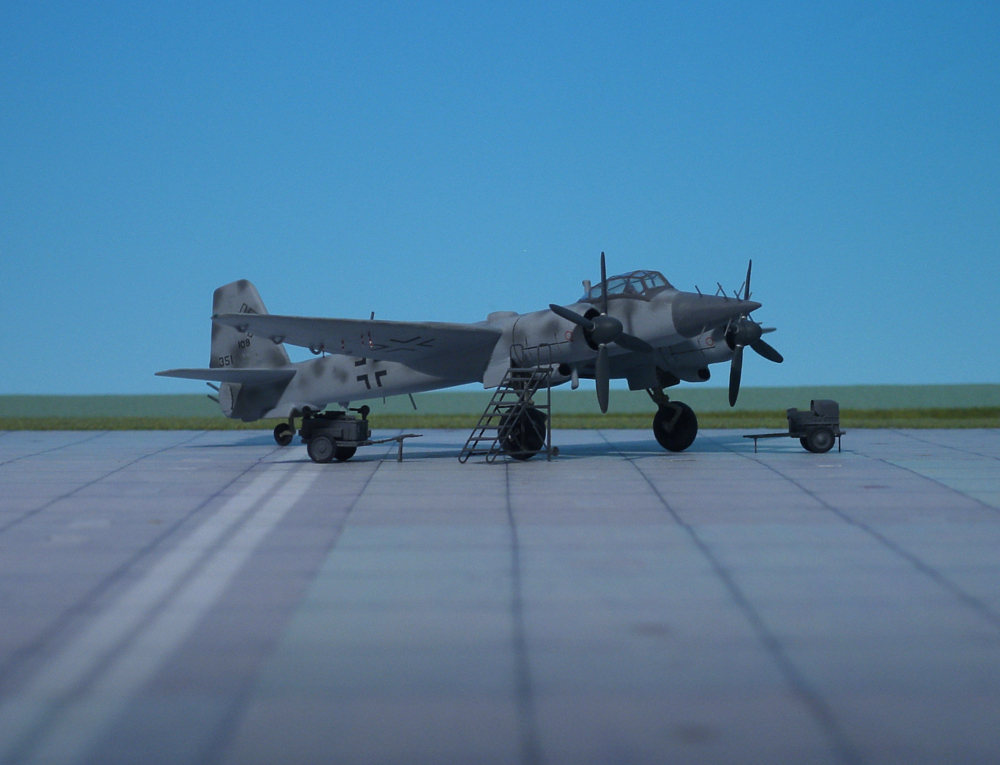
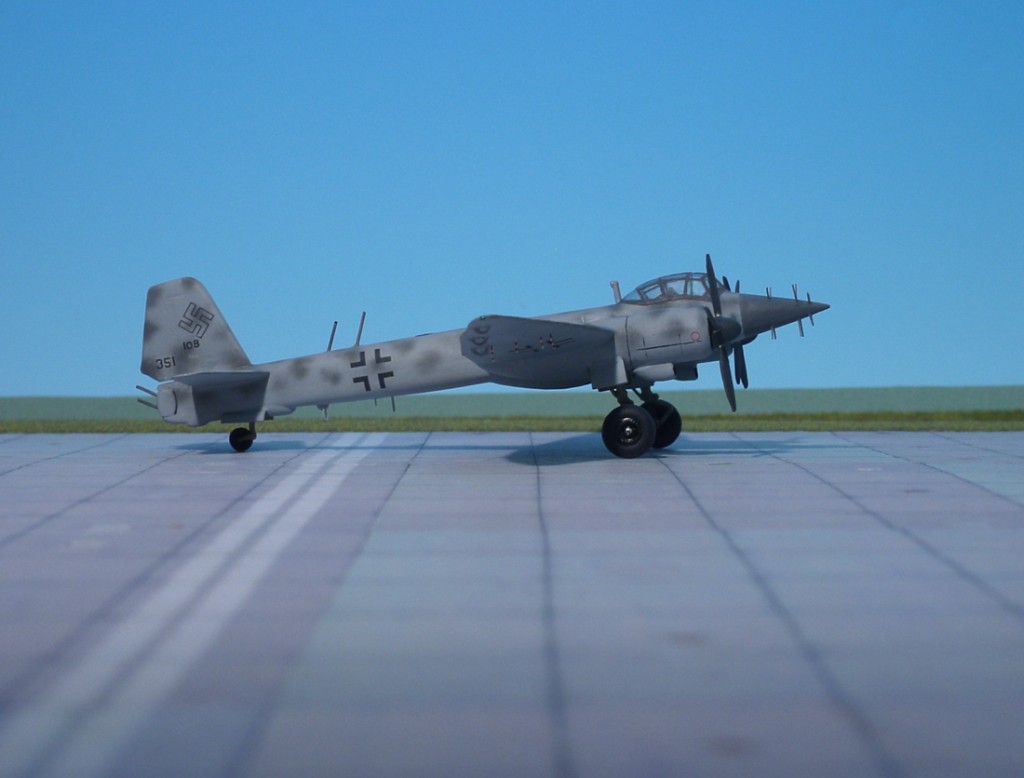
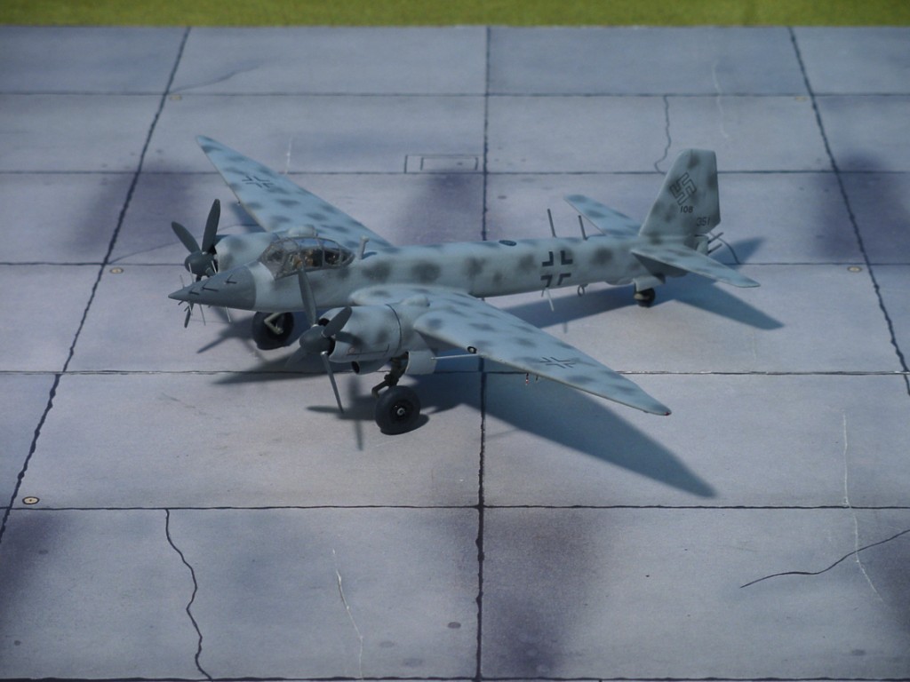
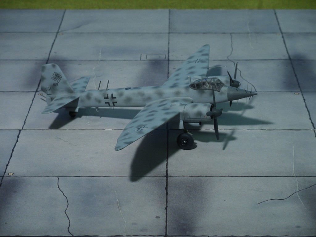
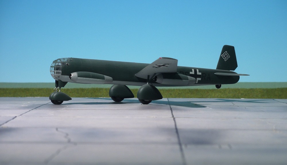
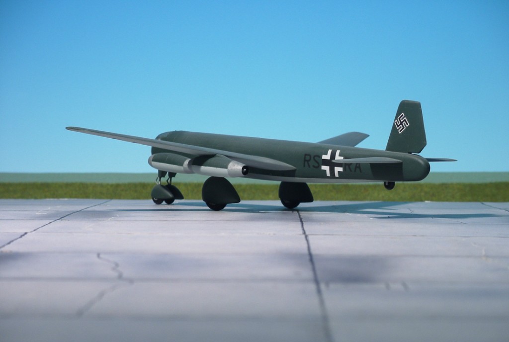
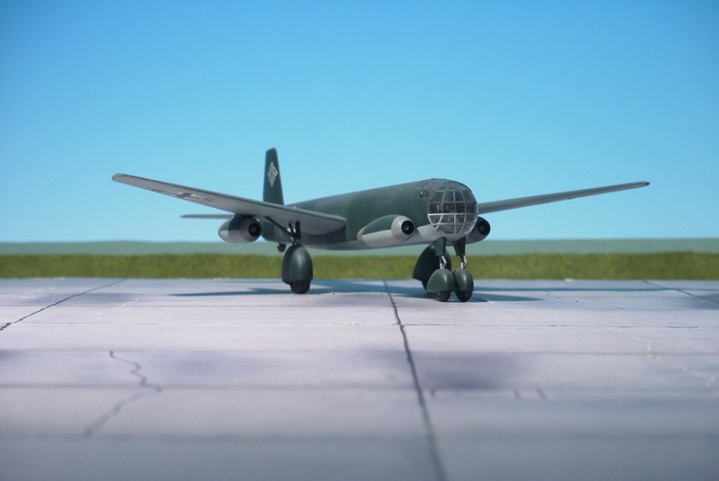
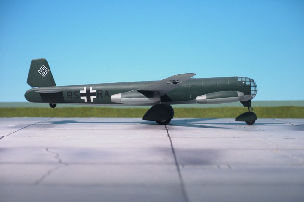
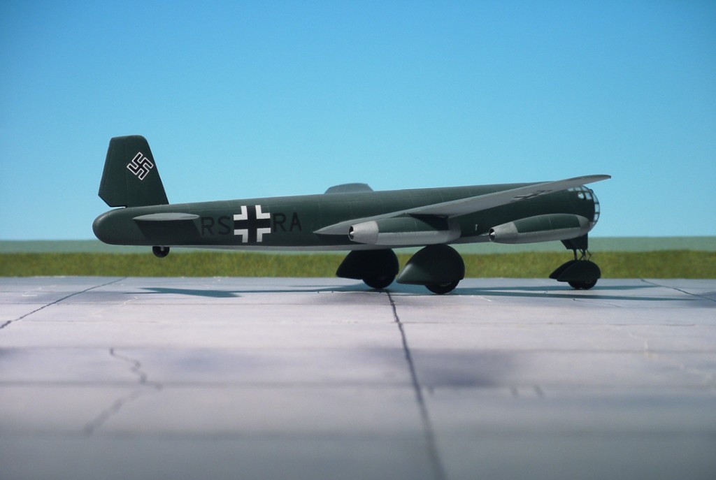
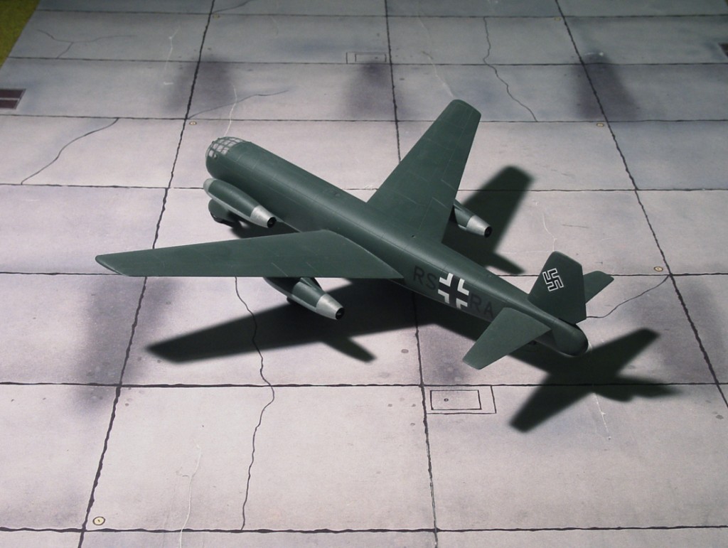
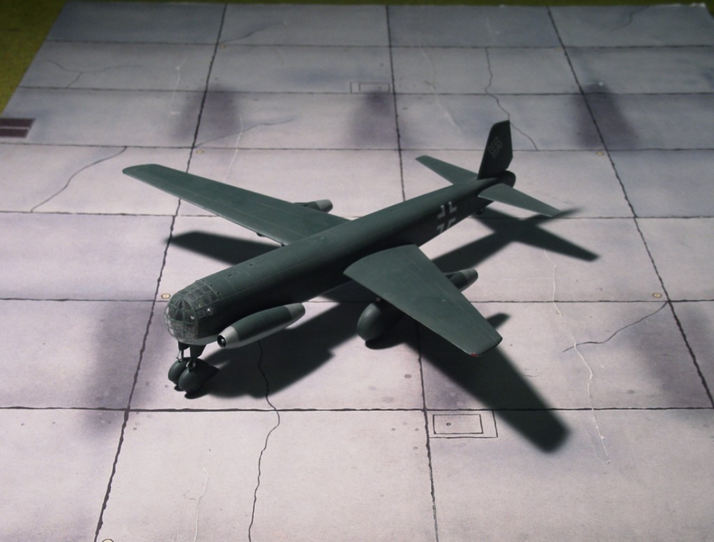
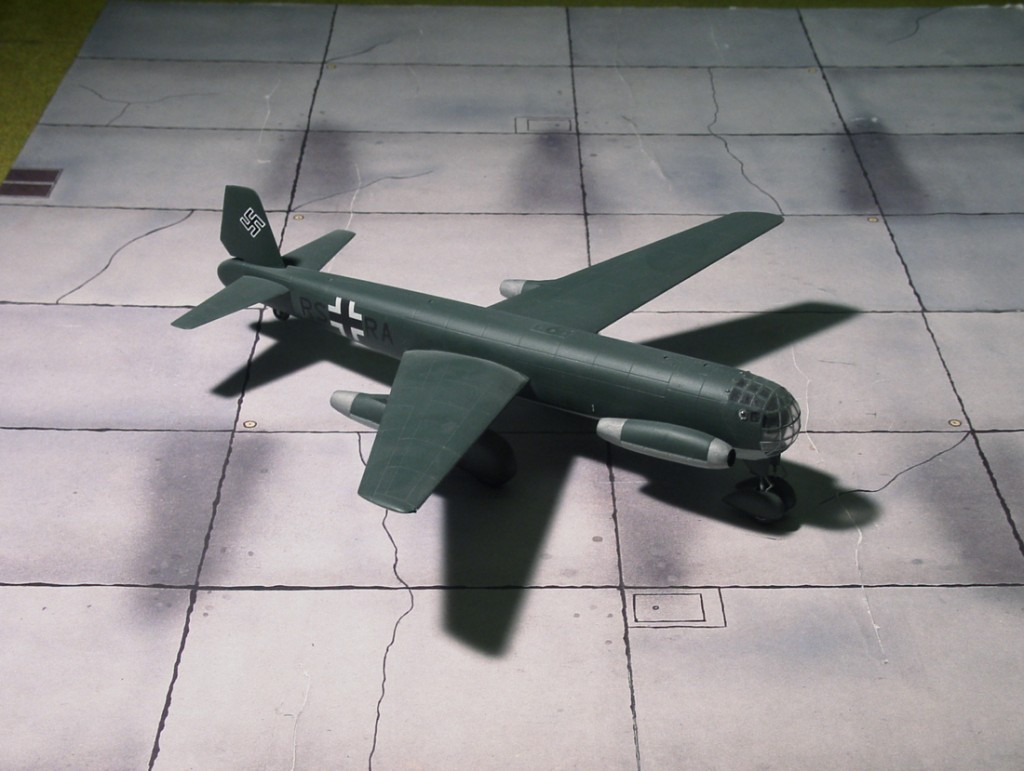
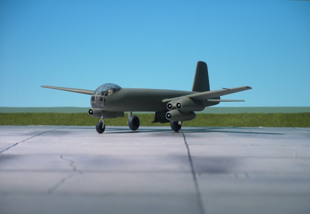
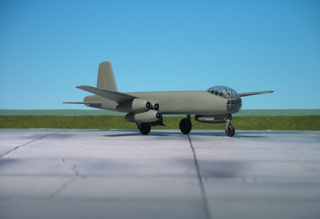
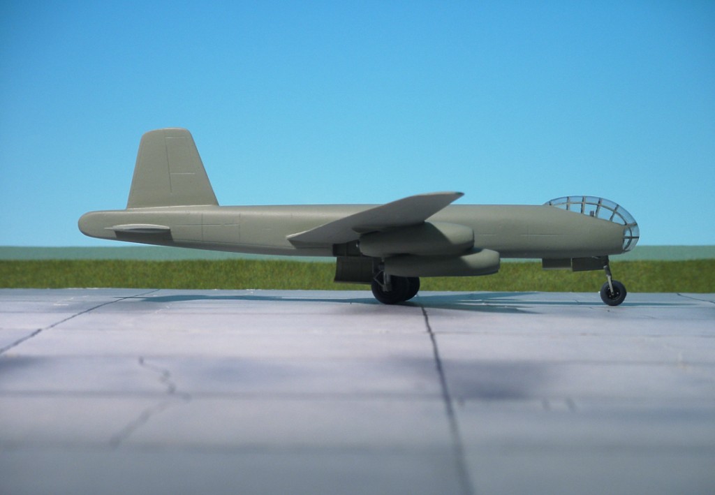
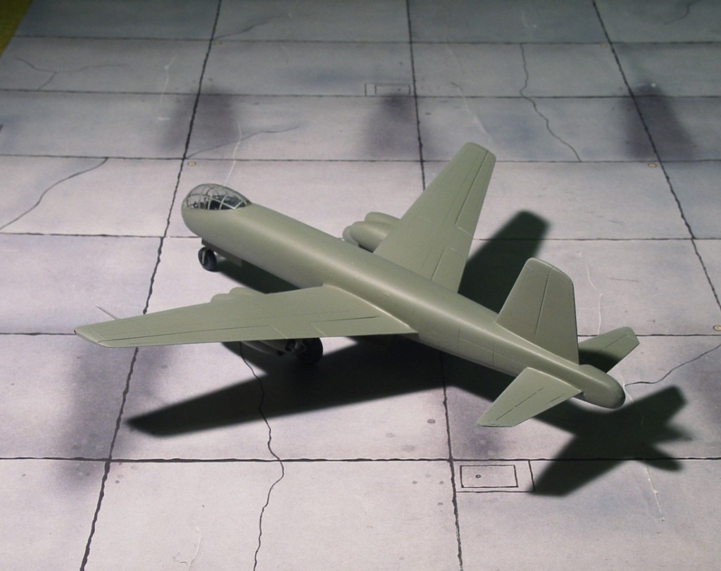
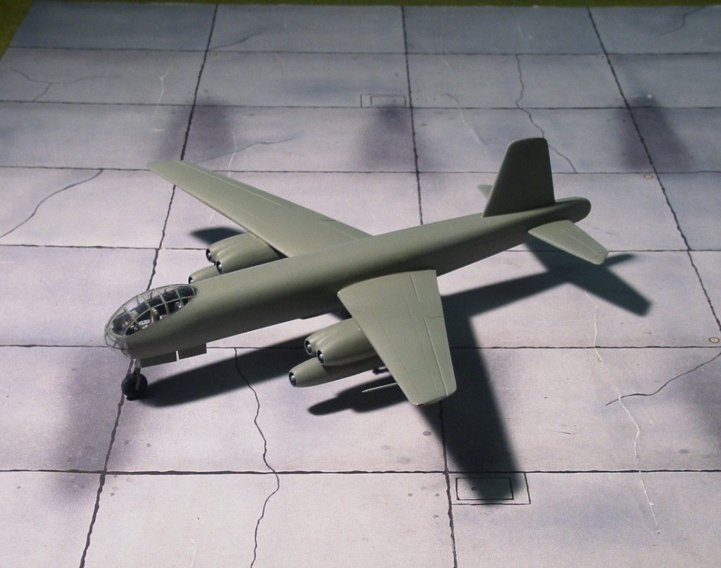
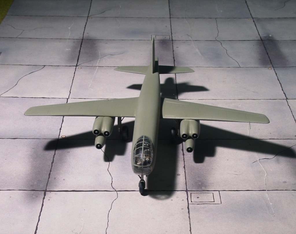
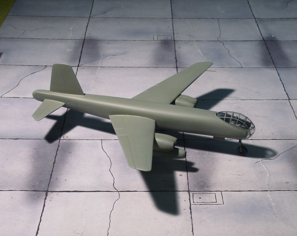
POWER PLANT: Six Junkers Jumo 004B-1 turbojet engines, rated at 950 kp each
PERFORMANCE: 534 mph
COMMENT: The Junkers EF 131 was, in essence, a hybrid airframe built from the components of the Junkers Ju 287 V2 and V3 of the Luftwaffe’s radical forward-swept-wing jet bomber. The V2 was nearly complete at the time of its capture by Soviet forces in 1945, and was taken into Red Air Force hands under military intelligence supervision along with the skeletal airframe of the barely-started V3. The V3 was to have been the first Ju 287 to be made to pre-production model specifications, and the eventual EF-131 was almost identical to it in terms of overall design. The airplane was completed and briefly test flown in the Soviet zone of occupied Germany, before being dismantled and transported to GOZ-1 (Gosoodarstvenny Optnyy Zavod – state experimental plant), at Dubna near Moscow. OKB-1 at GOZ-1 was formed with Dr. Baade as the chief designer, and a very talented team of German engineers seconded by the Soviet government. Extreme pressure was applied to get the aircraft ready to appear in the 1947 Aviation Day fly-past at Tushino airfield, but several factors combined to prevent the EF-131 from appearing. Flight testing in the USSR began on 23 May 1947, at the LII airfield, after the airframe had been strengthened. The first flight resulted in the port undercarriage collapsing due to a bolt failure, subsequent flight tests revealed major deficiencies such as nose wheel shimmy and tail surface vibration. Rectification of the defects caused many delays but the worst delays were caused by bureaucracy when it was decreed that foreign workers could not work at the LII airfield. The aircraft sat at LII over the winter but the harsh conditions caused the deterioration of rubber components and wiring, which required lengthy repairs. Preparations for resuming flight tests were almost complete in June 1948 when Ministry of Aircraft Industry ordered that further work on the EF-131 be discontinued. The Junkers EF-131 had become obsolete as newer Soviet-built engines with better performance became available (Ref.: 24).
Junkers EF 131
Junkers EF 131
Junkers EF 131
Junkers EF 131
Junkers EF 131
Junkers EF 131
Junkers EF 131 and Junkers Ju 287V-1
Junkers EF 131
Junkers EF 131
Junkers EF 131
Junkers EF 131
Junkers EF 131
Junkers EF 131 and Junkers Ju 287V-1
Scale 1:72 aircraft models of World War II
Mit der weiteren Nutzung unserer Webseite erklären Sie sich damit einverstanden, dass wir Cookies verwenden um Ihnen die Nutzerfreundlichkeit dieser Webseite zu verbessern. Weitere Informationen zum Datenschutz finden Sie in unserer Datenschutzerklärung.