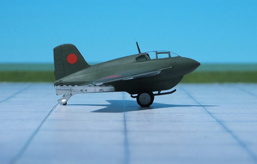
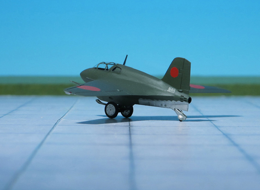
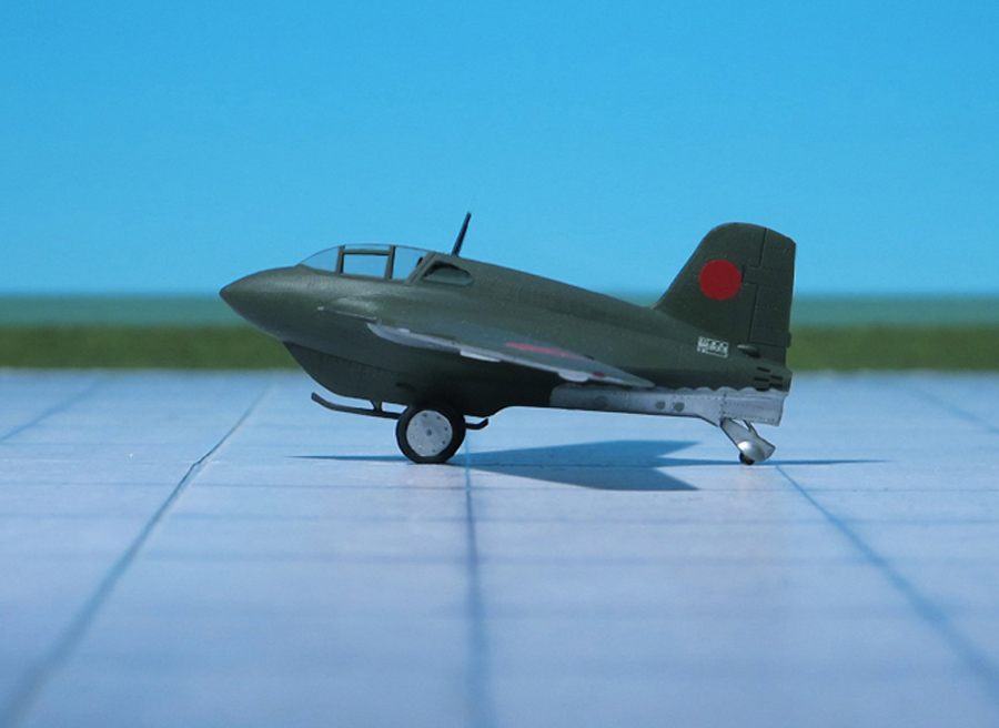
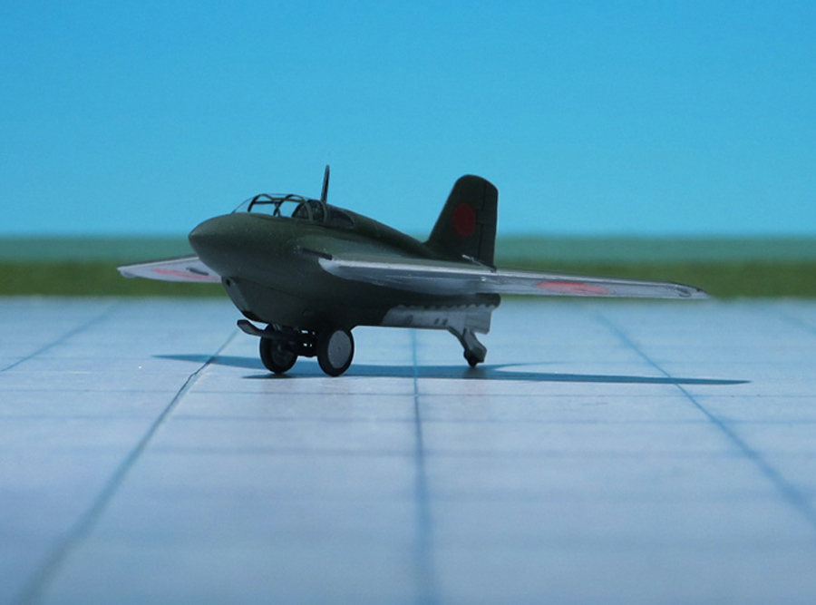
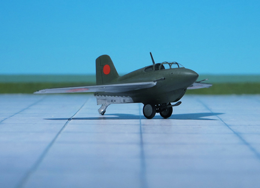
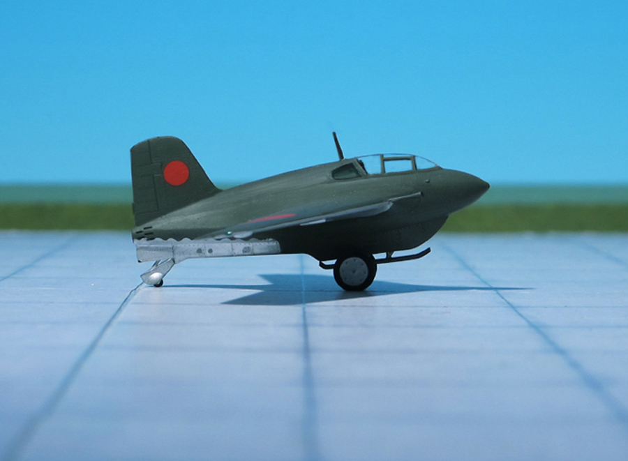
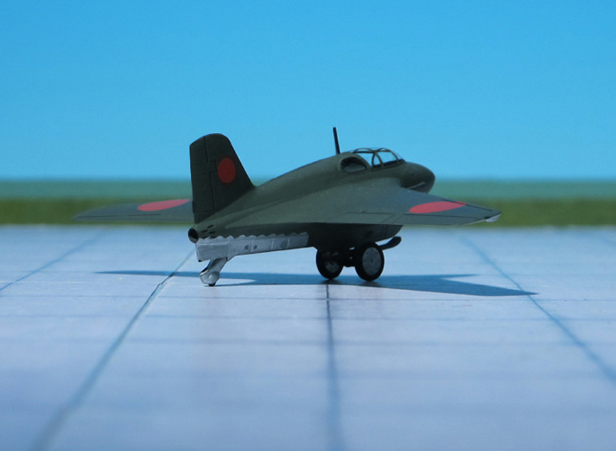
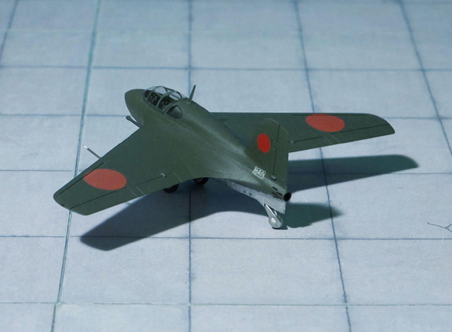
POWER PLANT: One Toku-Ro.2 /KR10) bi-fuel liquid rocket, rated at 1,500 kp thrust
PERFORMANCE: 559 mph at 32,808 ft
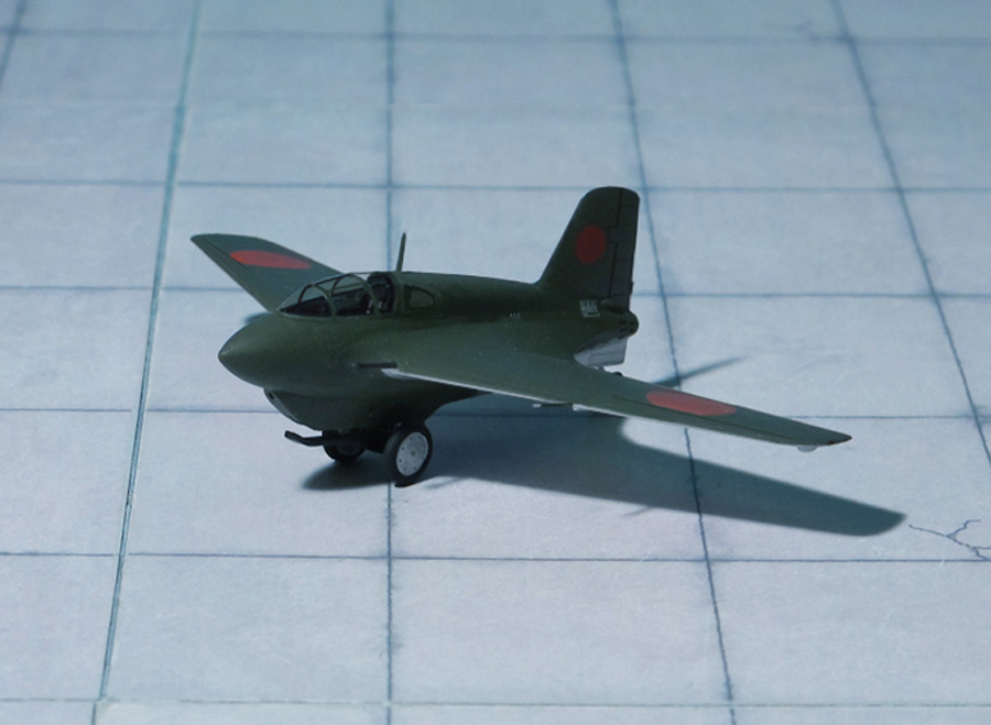
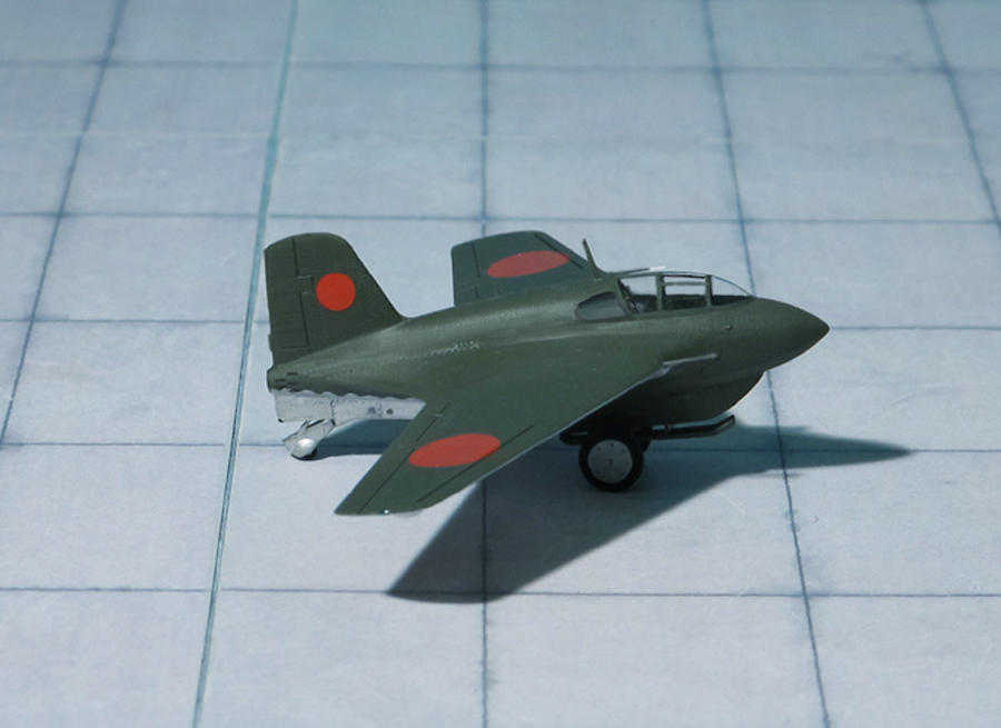
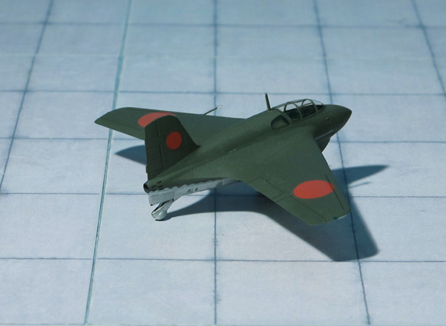
COMMENT: The Mitsubishi J8M “Shūsui” (literally “Autumn Water”, used as a poetic term meaning “Sharp Sword” deriving from the swishing sound of a sword) was a Japanese WW II rocket-powered interceptor aircraft closely based on the German Messerschmitt Me 163 “Komet” (Comet”). Built as a joint project for both the Japanese Navy and the Army Air Services, it was designated J8M (Navy) and Ki-200 (Army).
The Ki-200 and the J8M1 differed only in minor items, but the most obvious difference was the JAAF’s Ki-200 was armed with two 30 mm Type 5 cannon (with a rate of fire of 450 rounds per minute and a muzzle velocity of 720 m/s, while the J8M1 was armed with two 30 mm Ho-105 cannon (rate of fire 400 rounds per minute, muzzle velocity 750 m/s). The Ho-105 was the lighter of the two and both offered a higher velocity than the German MK 108 cannon of the Messerschmitt Me 163 (whose muzzle velocity was 520 m/s).
The Toko Ro.2 (KR10) rocket motor did not offer the same thrust rating as the original, and Mitsubishi calculated that the lighter weight of the J8M1 would not offset this. Performance would not be as good as that of the Me 163 “Komet”, but was still substantial. The engine still used the German propellants of T-Stoff oxidizer and C-Stoff fuel (hydrogen peroxide/methanol-hydrazine), known in Japan as “Ko” and “Otsu” respectively.
At the end of the war “Shusui” production was already under way. Additionally, the Navy had instructed Mitsubishi, Nissan and Fuji to design a further Navy version as J8M2 with only one cannon thus giving additional space for more fuel and by that more endurance, while the Army ordered Rikugun Kokugijutsu Kenkyujo the development of an enlarged version of the Ki-200 with increased fuel tankage, known as Mitsubishi Ki-202 “Shusui Kai” to be built by Mitsubishi (Ref.: 1, 24).
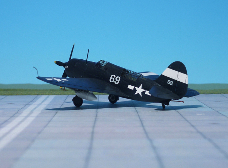
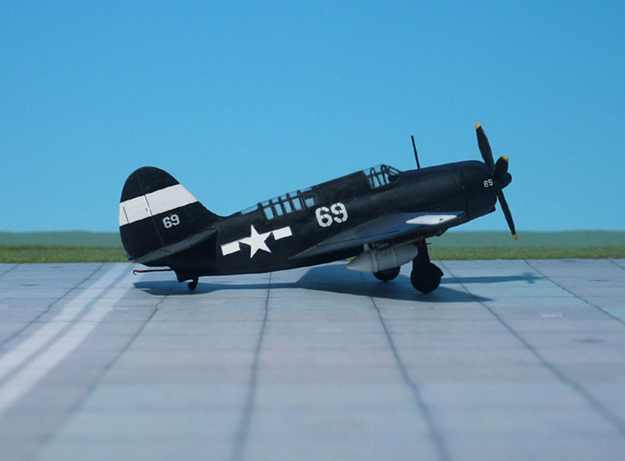
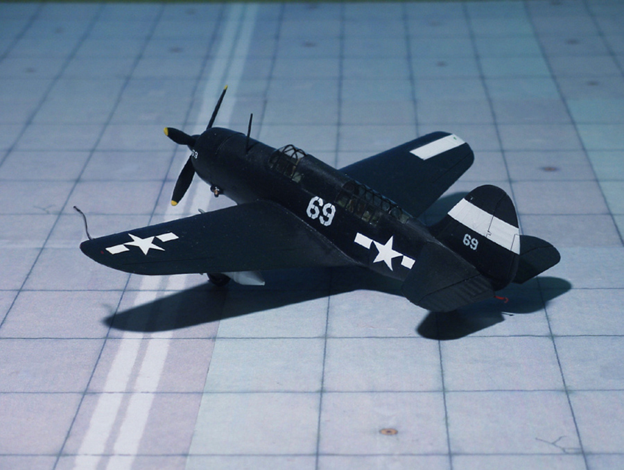
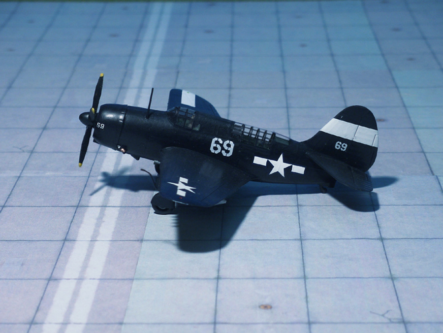
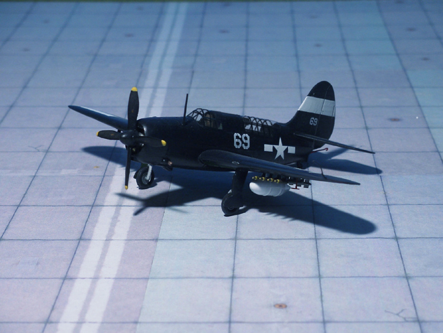
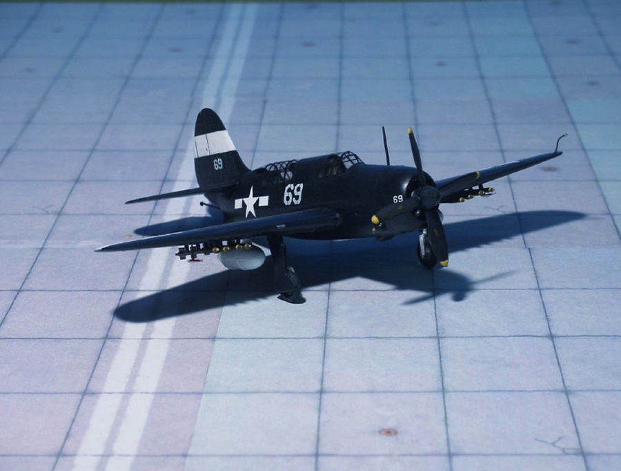
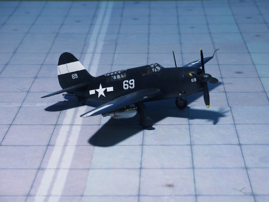
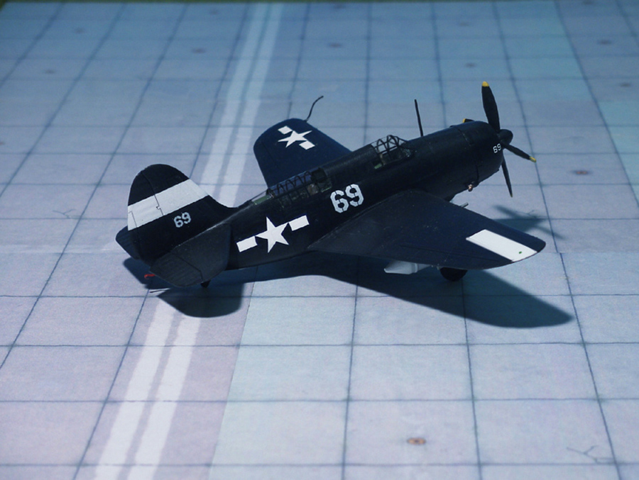
POWER PLANT: One Wright R-2600-20 “Twin Cyclone” radial engine, rated at 1,900 hp
PERFORMANCE: 295 mph at 16,700 ft
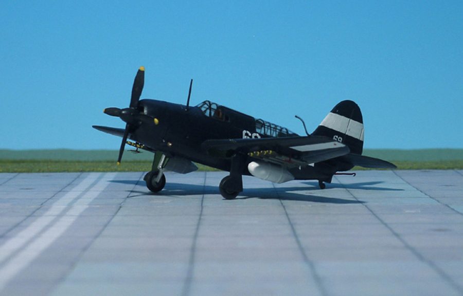
COMMENT: The Curtiss SB2C “Helldiver” was developed to replace the Douglas SBD “Dauntless”. It was a much larger aircraft, able to operate from the latest aircraft carriers and carry a considerable array of armament. It featured an internal bomb bay that reduced drag when carrying heavy ordnance. Saddled with demanding requirements set forth by both the U.S. Marines and United States Army Air Forces, the manufacturer incorporated features of a “multi-role” aircraft into the design.
The first prototype made its maiden flight on December 1940. It crashed on February 1941 when its engine failed on approach, but Curtiss was asked to rebuild it. The fuselage was lengthened and a larger tail was fitted, while an autopilot was fitted to help the poor stability. The revised prototype flew again on October 1941, but was destroyed when its wing failed during diving tests on December 1941.
Large-scale production had already been ordered on November 1940, but a large number of modifications were specified for the production model. Fin and rudder area were increased, fuel capacity was increased, self-sealing tanks were added and the fixed armament was doubled to four 12.7 mm machine guns in the wings, compared with the prototype’s two cowling guns. The SB2C-2 was built with larger fuel tanks, improving its range considerably.
The program suffered so many delays that the Grumman TBF “Avenger” entered service before the “Helldiver”, even though the “Avenger” had begun its development two years later. Nevertheless, production tempo accelerated with production at Columbus, Ohio and two Canadian factories.
The U.S. Navy would not accept the SB2C until 880 modifications to the design and the changes on the production line had been made, delaying the Curtiss “Helldiver’s” combat debut until November 1943. Among its major faults, the “Helldiver” was underpowered, had a shorter range than the Douglas SBD, was equipped with an unreliable electrical system, and was often poorly manufactured. The solution to these problems began with the introduction of the SB2C-3 beginning in 1944, which used the R-2600-20 Twin Cyclone engine with 1,900 hp and Curtiss’ four-bladed propeller. This substantially solved the chronic lack of power that had plagued the aircraft
In operational experience, it was found that the U.S. Navy’s Grumman F6F “Hellcat” and Vought F4U “Corsair” fighters were able to carry an equally heavy bomb load against ground targets and were vastly more capable of defending themselves against enemy fighters. The “Helldiver”, however, could still deliver ordnance with more precision against specific targets and its two-seat configuration permitted a second set of eyes. A “Helldiver” also has a significant advantage in range over a fighter while carrying a bombload, which is extremely important in naval operations.
The advent of air-to-ground rockets ensured that the SB2C-4 was the last purpose-built dive bomber produced. Rockets allowed precision attack against surface naval and land targets, while avoiding the stresses of near-vertical dives and the demanding performance requirements that they placed on dive bombers.
Crew nicknames for the aircraft included the “Big-Tailed Beast”, or just the derogatory “Beast” due to its size, weight, and reduced range compared to the SBD it replaced. A total of 7,140 Curtiss SB2C “Helldivers” were produced in World War II (Ref.: 24).
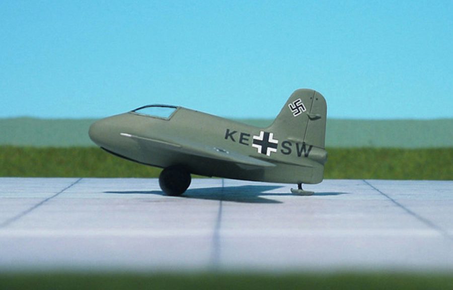
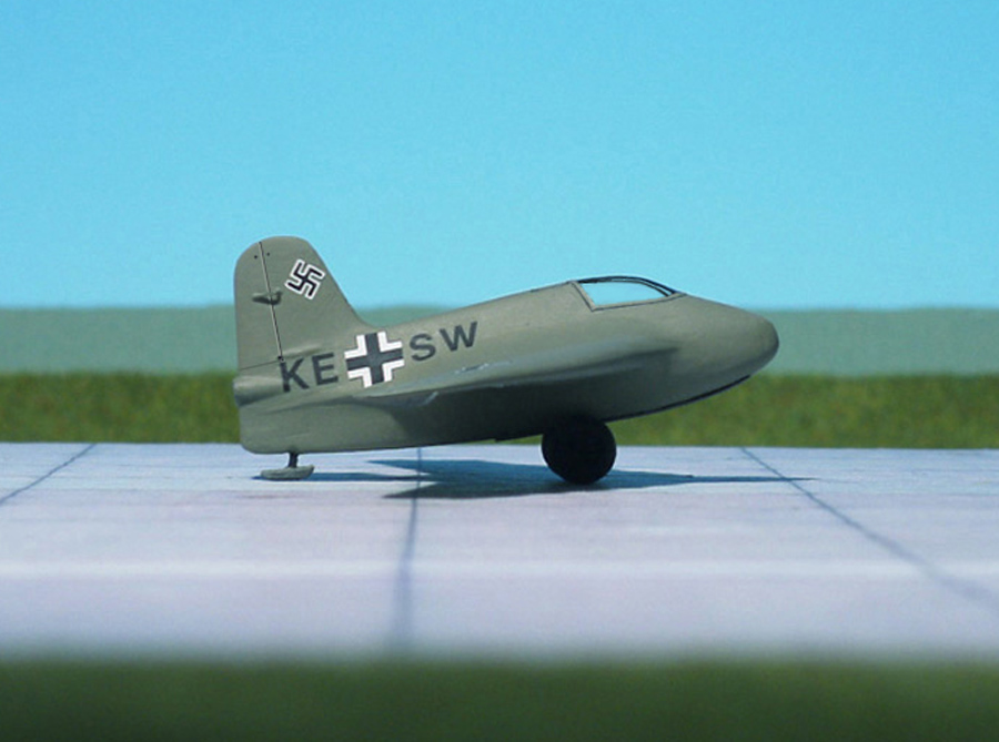
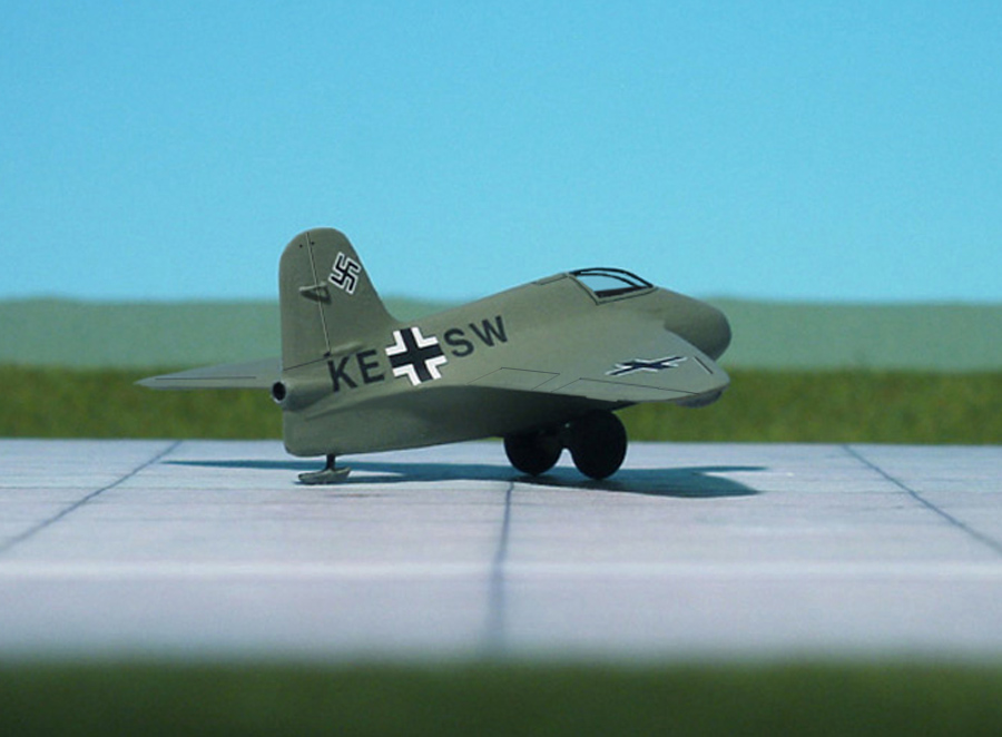
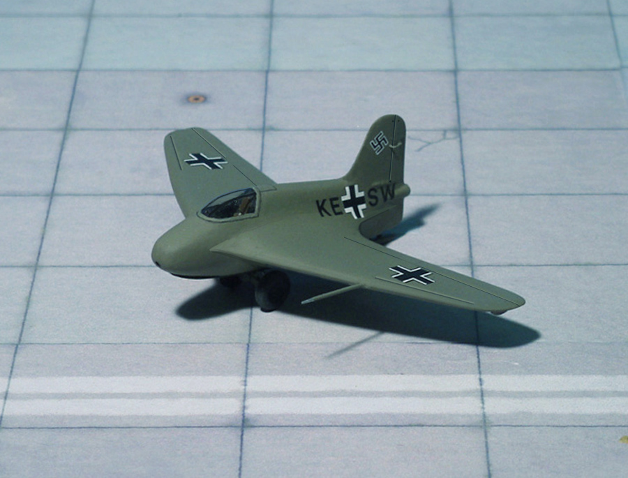
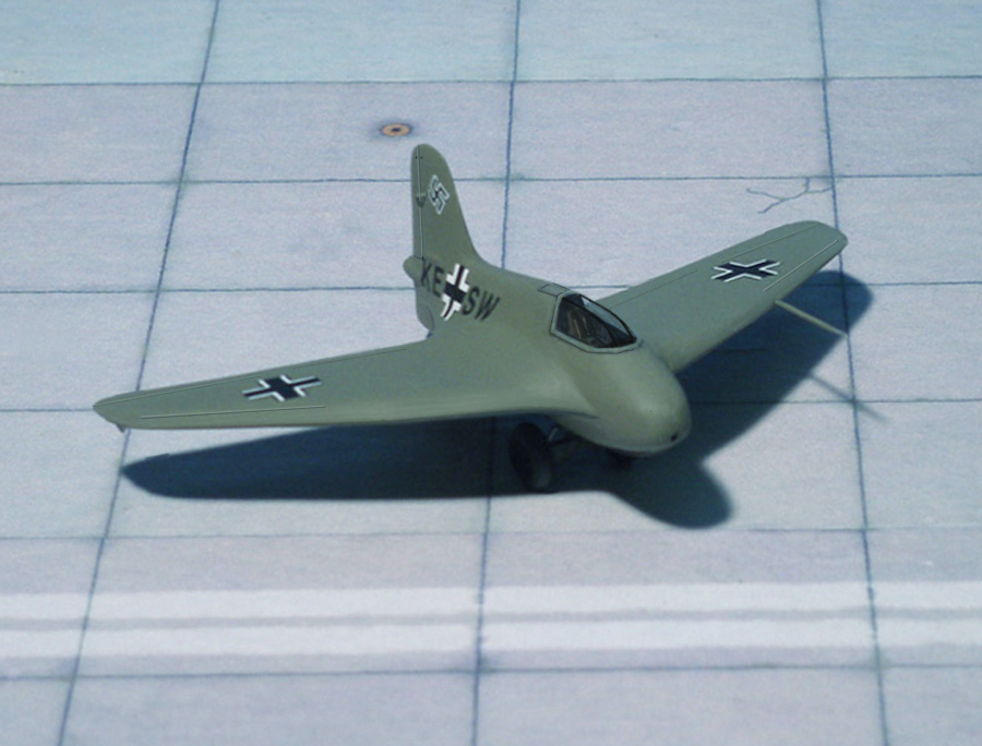
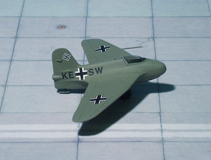
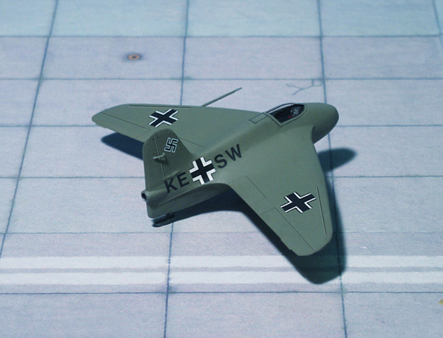
POWER PLANT: One Walter R II-203b bi-fuel liquid rocket, rated between 150 to 750 kp
PERFORMANCE: 550 mph
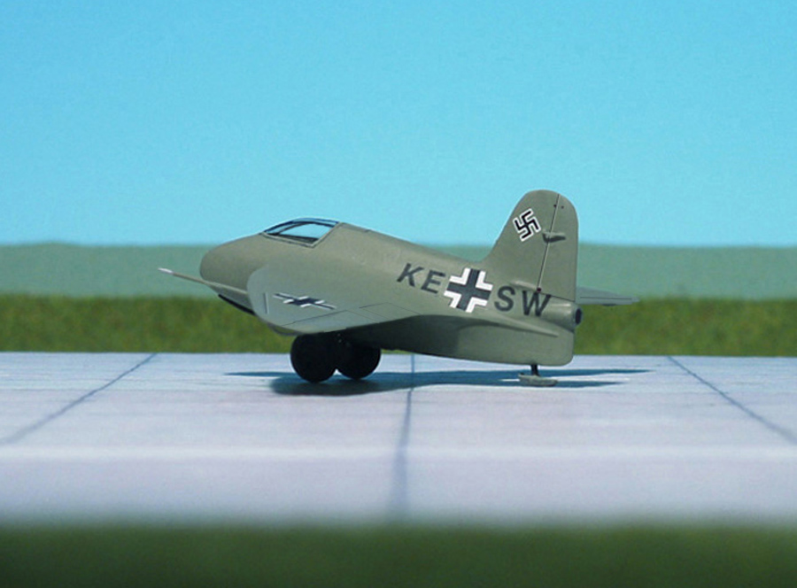
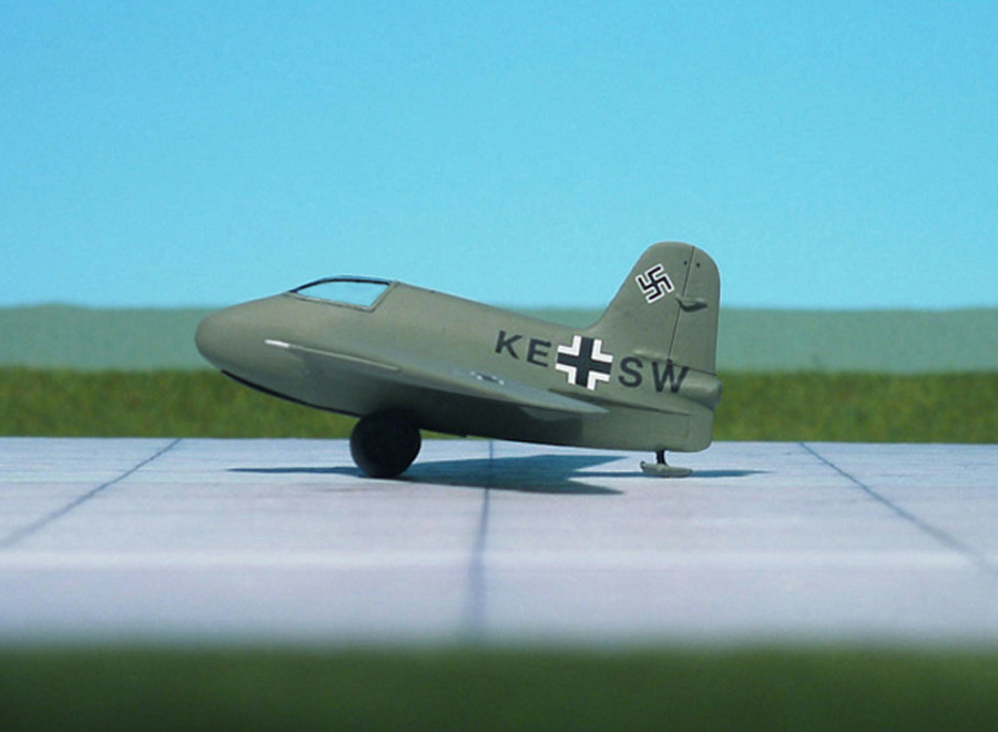
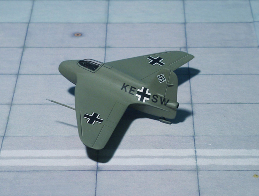
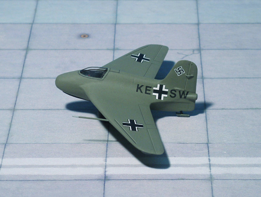
COMMENT: In early 1941, based on the success by the DFS 194, production of a prototype series, known as the Messerschmitt Me 163, began. Secrecy was such that the RLM’S “GL/C” airframe number, 8–163, was actually that of the earlier, pre-July 1938 Messerschmitt Bf 163. It was thought that intelligence services would conclude any reference to the number “163” would be for that earlier design. Five prototypes (V1 to V5) were ordered designated Messerschmitt Me 163A “Komet” (“Comet”).
In May 1941 the Messerschmitt Me 163A V4 was shipped to Peenemünde to receive the Walter HWK RII-203 engine. By 2 October 1941, the Me 163A V4, bearing the radio call sign letters, or Stammkennzeichen, “KE+SW”, set a new world speed record of 624.2 mph. Piloted by Heini Dittmar, the fully tanked up aircraft was towed to an altitude of 13,120 ft behind a Messerschmitt Me 110C. After casting-off from the tow-plane, the rocket engine was fired. At about Mach 0.84 compressibility effects resulted in a sudden loss of stability, and the Me 163A V4 went into a dive. Dittmar promptly cut the rocket motor, the aircraft decelerating rapidly and full control being restored. The aircraft was landed on skids with no apparent damage to the aircraft during the attempt.
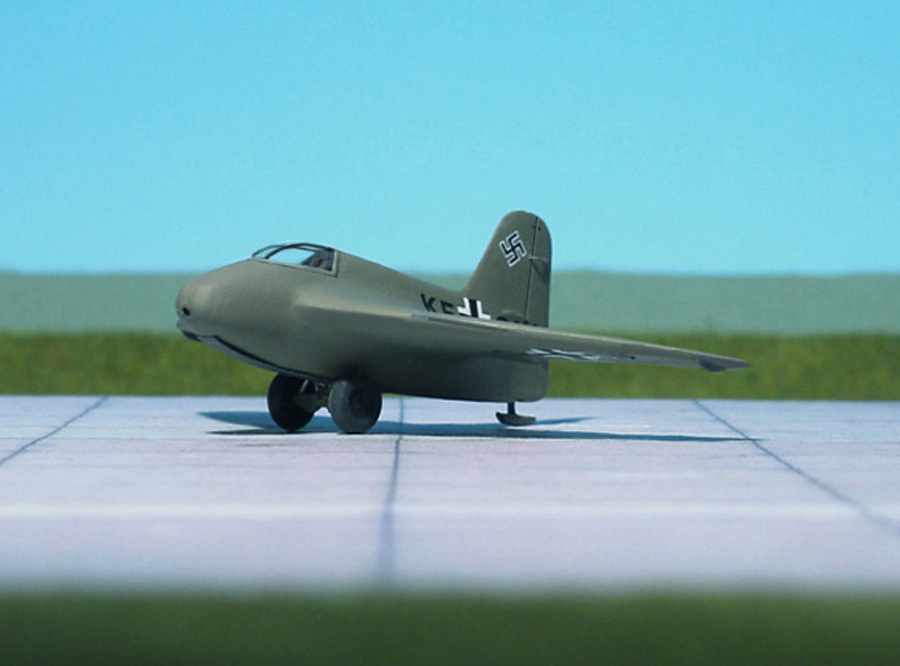
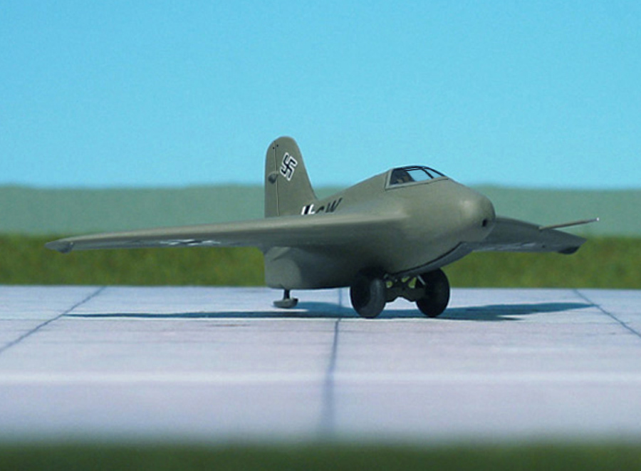
During further flight testing, the superior gliding capability of the Me 163A proved detrimental to safe landing. As the now un-powered aircraft completed its final descent, it could rise back into the air with the slightest updraft. Since the approach was unpowered, there was no opportunity to make another landing pass. For production models, a set of landing flaps allowed somewhat more controlled landings. This issue remained a problem throughout the program. Nevertheless, the overall performance was tremendous, and plans were made to put the Messerschmitt Me 163 squadrons all over Germany in 40-kilometre rings (25 mi) around any potential target. Development of an operational version was given the highest priority.
Five prototype Me 163A V-series aircraft were built, adding to the original DFS 194 (V1), followed by eight pre-production examples designated as “Me 163 A-0”.
Note: Some postwar aviation history publications stated that the Messerschmitt Me 163A V3 (CD+IL) was thought to have set the record. The 1,004 km/h record figure would not be officially approached until the postwar period by the new British and American turbojet-powered aircraft. It was not surpassed (except by the later Me 163B V18 in 1944, but seriously damaged by the attempt) until the American Douglas D-558-I “Skystreak” turbojet-powered research aircraft did so on 20 August 1947 with no damage (Ref.: 24).
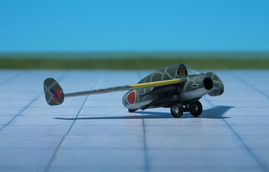
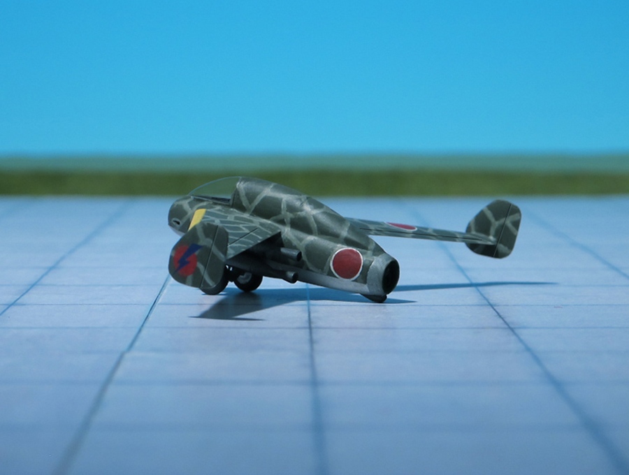
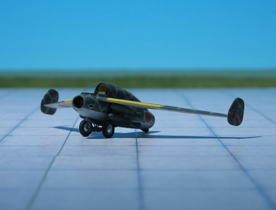
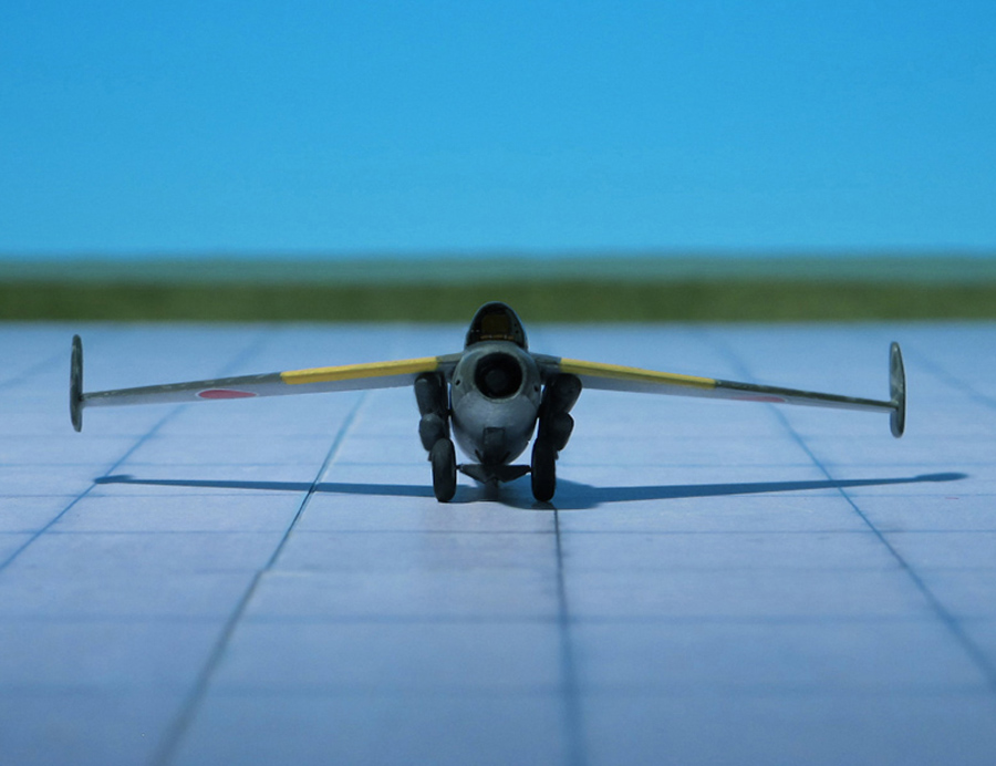
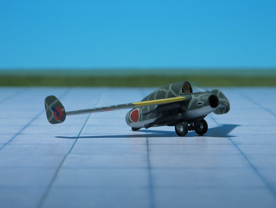
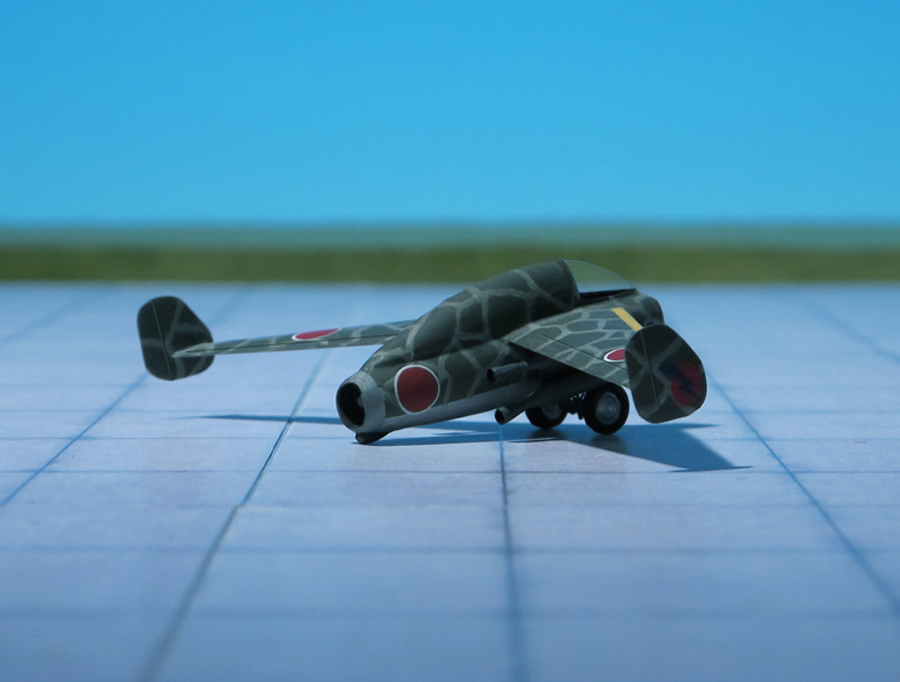
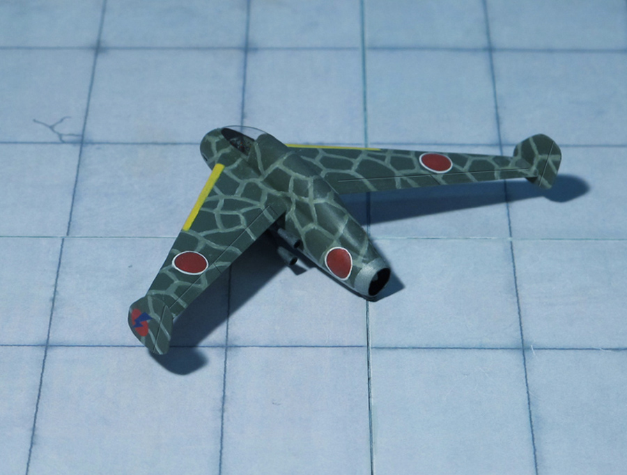
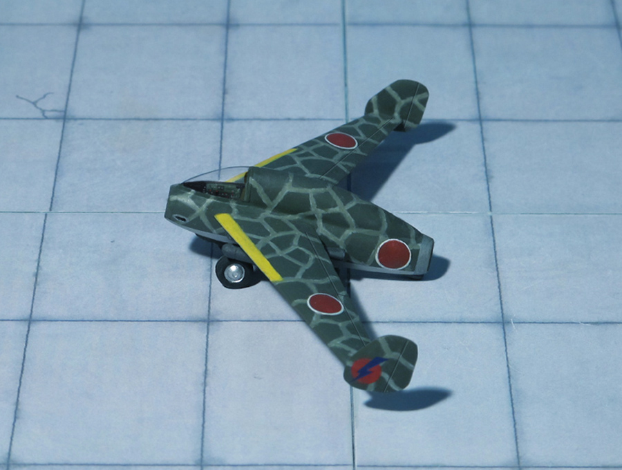
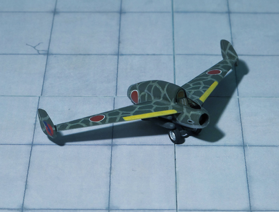
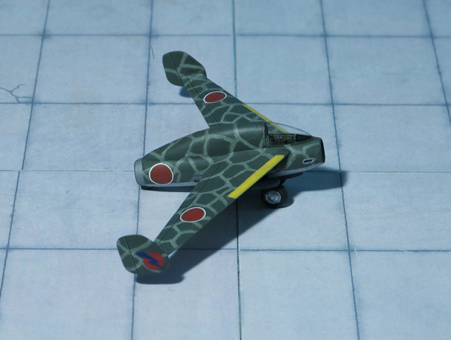
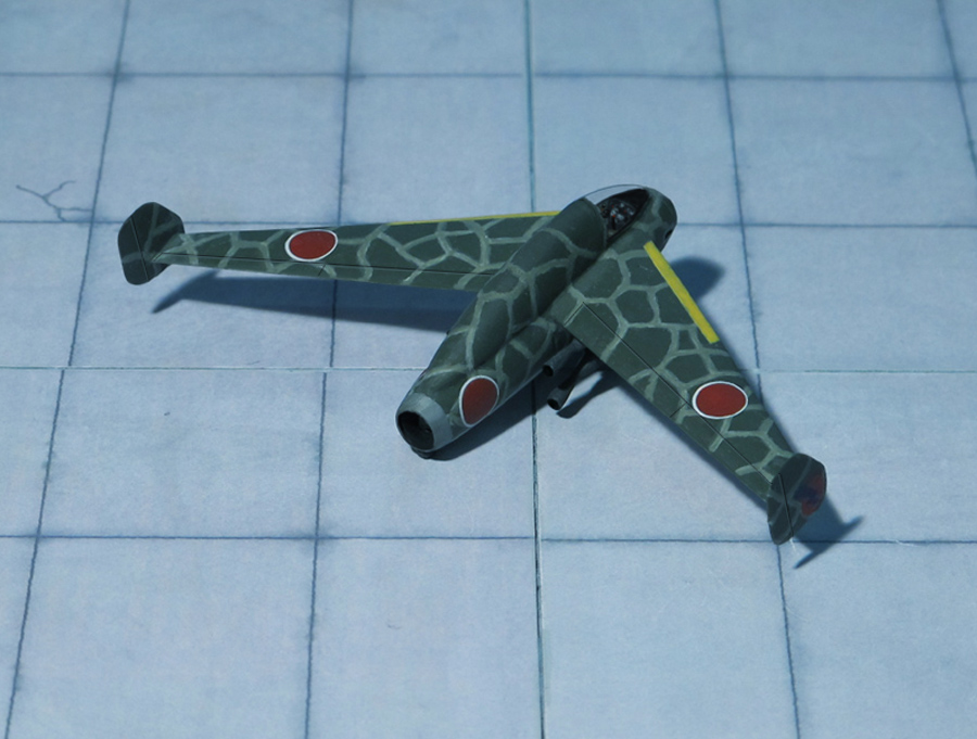
POWER PLANT: One Kayaba Model 1 ramjet engine rated at 750 kp thrust at 457 mph and four solid fuel rocket boosters for take-off, rated at 7.200 kp thrust
PERFORMANCE: 559 mph (estimated)
COMMENT: The Kayaba “Katsuodori” (“Booby Gannet”) was the result of the endeavor to design a single-seat, ramjet-powered interceptor-minded platform which utilized a short, tailless fuselage configuration with swept-back wing main planes. The cockpit would be held well-forward and offered exceptional vision for the pilot. The mid-mounted main planes were affixed ahead of midship with each tip capped by small vertical stabilizers. The ramjet propulsion system was buried within the tubular fuselage and a rocket-assist scheme (consisting of four externally-held rocket pods) was to be used. The rocket pods were installed under the wing roots and jettisoned once their usefulness had run out. Having achieved the required speeds, the aircraft would then continue on under ramjet power with a flying window of about 30 minutes being estimated. To aspirate the ramjet, the nose section featured an air intake. No conventional undercarriage was provided. Instead the aircraft would glide back home powerless and land on a belly-mounted skid. The ramjet under consideration for the project became the Kayaba Model 1 which promised 750 kp thrust output.
Since the aircraft never achieved prototype form, performance specifications were estimated and this included a maximum speed of 560 miles per hour with a rate-of-climb around 11,000 feet-per-minute. The latter would prove a good quality to have in interception sorties. The service ceiling was listed at 49,215 feet
As an interceptor attempting to tackle very large, slow-moving (but well-defended) targets, it was seen to arm the fighter appropriately through 2 x 30mm Ho-301 series cannons – this was a suitable arrangement to counter even the high-flying and technologically advanced Boeing B-29 “Superfortress” which had made its presence known since mid-1944. The cannons would have been embedded in the sides of the nose.
Design work on the “Katsuodori” progressed into 1943 and plans were underway to begin construction of a working prototype for the following year. However, Japan’s fortunes in the war had worsened into 1944 and the attention of authorities turned to more viable military weapons such as the Rikugun (Mitsubishi) Ki-202 “Sharp Sword”, based on a rocket-powered interceptor developed by Mitsubishi as Ki-200 “Shusui” for the IJAAF and J8M-1 for the IJNAF on the basis of the German Messerschmitt Me 163 “Komet” (Ref.: 24).
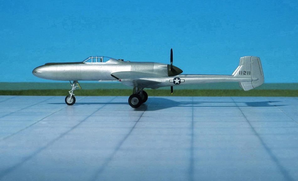
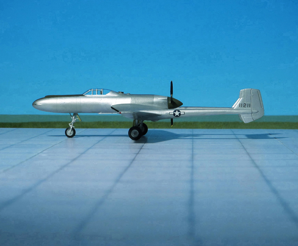
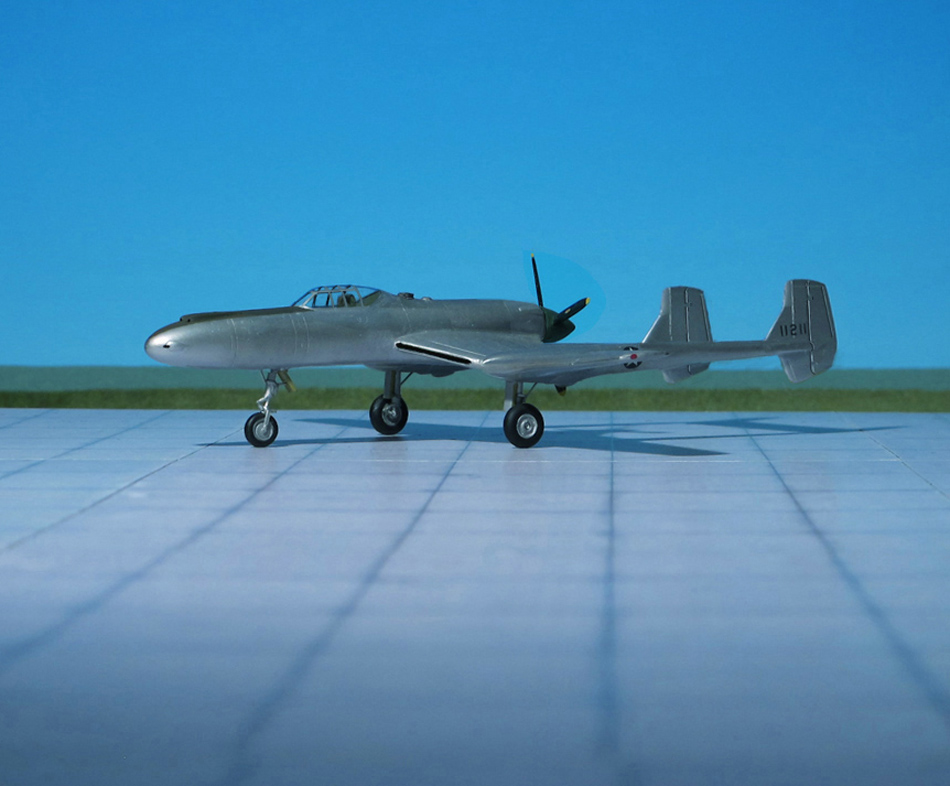
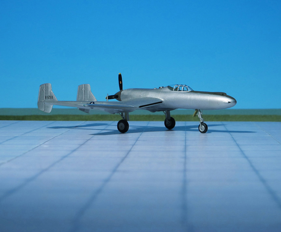
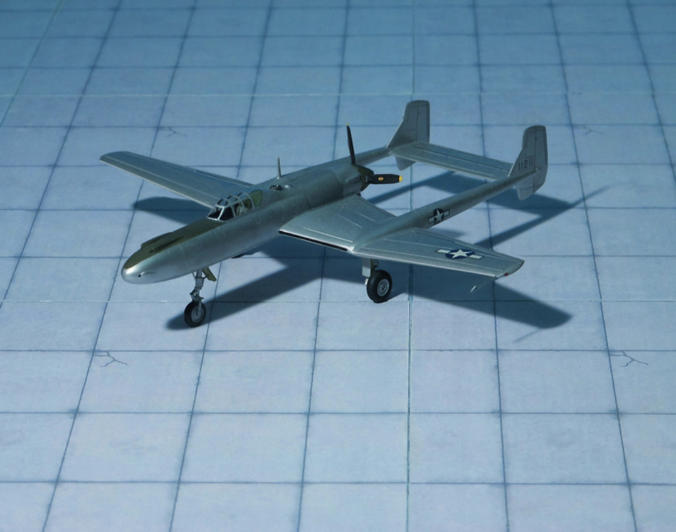
POWER PLANT: One Lycoming XH-2470-1 liquid-cooled engine, rated at 2,300 hp
PERFORMANCE: 381 mph at 28,500 ft
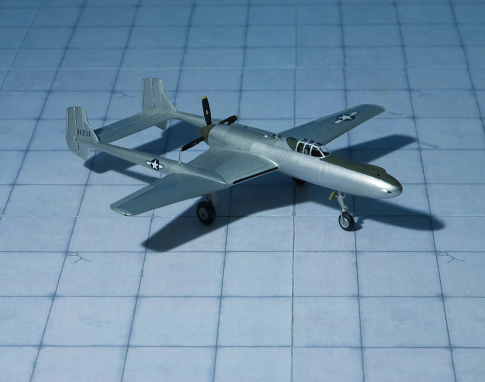
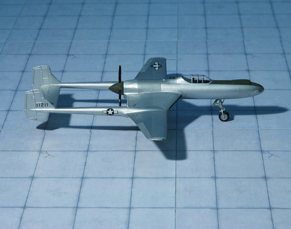
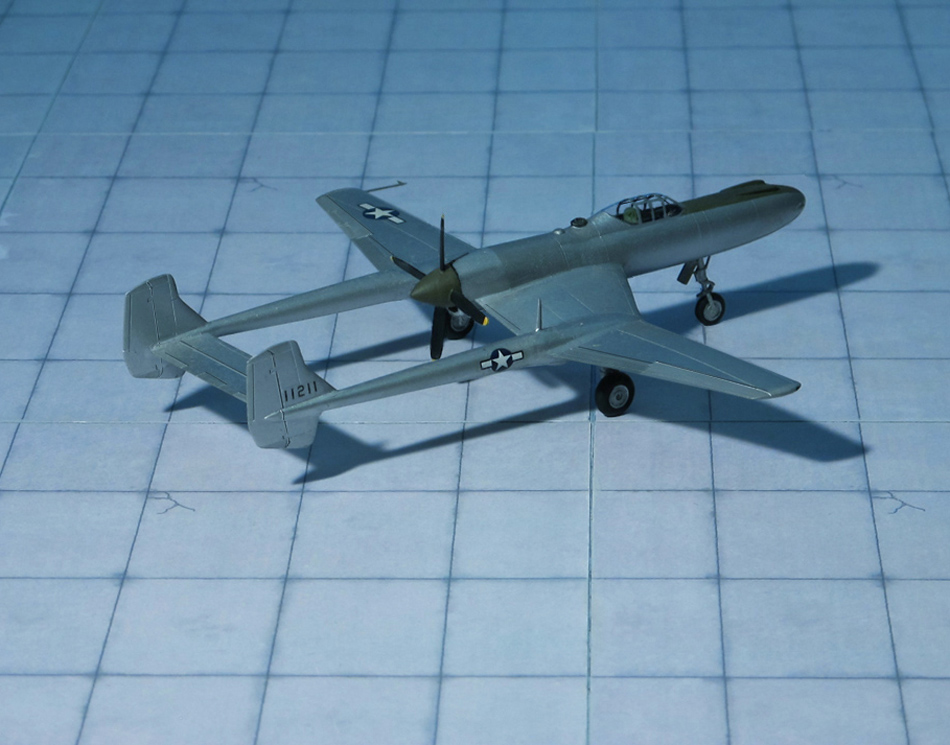
COMMENT: The Vultee Company had submitted a proposal in response to a US Army Air Corps request for an unusual configuration. The Vultee design won the competition, beating the Curtiss XP-55 “Ascender” and Northrop XP-56 “Black Bullet”. Vultee designated it Model 84, a descendant of their earlier Model 78. After completing preliminary engineering and wind tunnel tests, a contract for a prototype was awarded on January 1941. A second prototype was ordered on March 1942..
The XP-54 was designed with a pusher engine in the aft part of the fuselage. The tail was mounted rearward between two mid-wing booms, with the 12-ft propeller between them. The design included a “ducted wing section” developed by the NACA (National Advisory Committee of Aeronautics) that enabled installation of cooling radiators and intercoolers in the inverted gull wing. The Pratt & Whitney X-1800 engine was initially proposed as the power plant but after its development was discontinued, the liquid-cooled Lycoming XH 2470 was substituted.
In September 1941, the XP-54 mission was changed from low altitude to high altitude interception. Consequently, a turbo-supercharger and heavier armor had to be added, and the estimated empty weight increased from 5,200 to 8,200 kg.
The XP-54 was unique in numerous ways. The pressurized cockpit required a complex entry system: the pilot’s seat acted as an elevator for cockpit access from the ground. The pilot lowered the seat electrically, sat in it, and raised it into the cockpit. Bail-out procedure was complicated by the pressurization system and necessitated a downward ejection of the pilot and seat in order to clear the propeller arc. Also, the nose section could pivot through the vertical, three degrees up and six degrees down. In the nose, two 37 mm T-9 cannon were in rigid mounts while two .50 cal. machine guns were in movable mounts. Movement of the nose and machine guns was controlled by a special compensating gun sight. Thus, the cannon trajectory could be elevated without altering the flight attitude of the airplane. The large nose section gave rise to its whimsical nickname, the “Swoose Goose”, inspired by a song about Alexander who was half swan and half goose: “Alexander was a swoose.”
Flight tests of the first prototype, Serial Nr. 41-1210, began on 15 January 1943. Initial trials showed performance to be substantially below guarantees. At the same time, development of the XH-2470 engine was discontinued and, although it appeared possible to substitute the Allison V-3420 engine without substantial airframe changes, the projected delay and costs resulted in a decision not to consider production buys.
The prototypes continued to be used in an experimental program until problems with the Lycoming engines and lack of spare parts caused termination. The second prototype, 42-108994 (but mistakenly painted as 42-1211) equipped with an experimental General Electric supercharger, only made one flight before it was relegated to a “parts plane” in order to keep the first prototype in the air (Ref.: 24).
ACCOMMODATION: One or two pilots + 23 troops or equivalent freight
POWER PLANT: None
PERFORMANCE: 186 mph
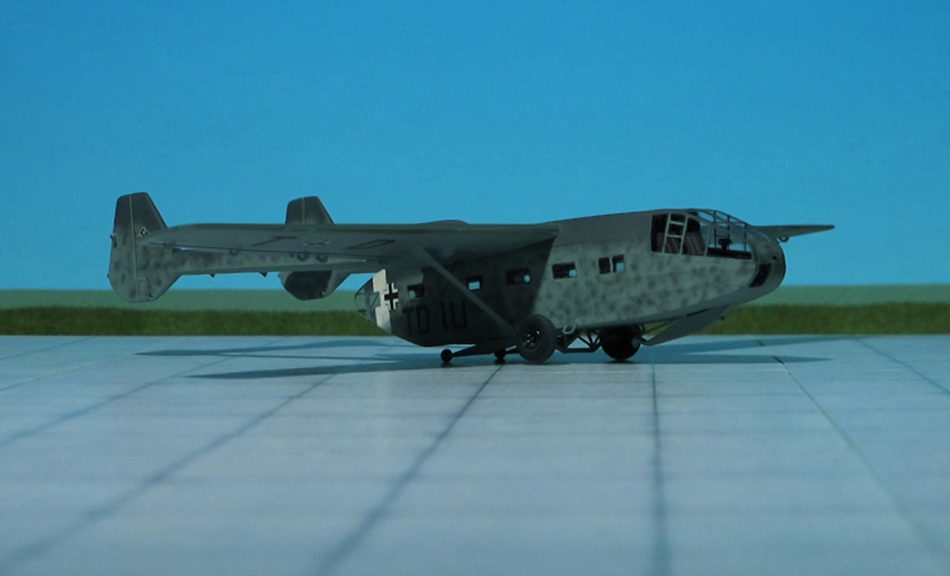
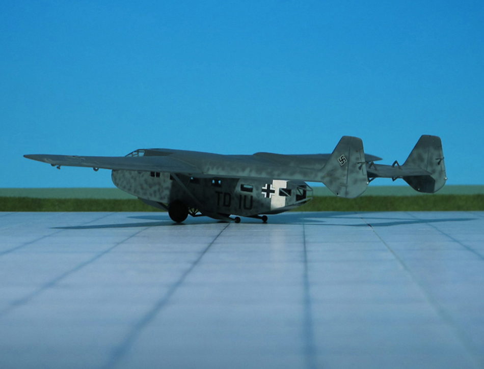
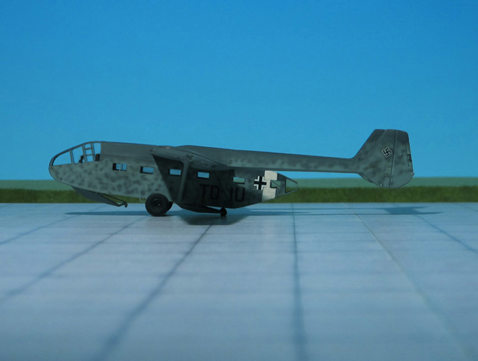
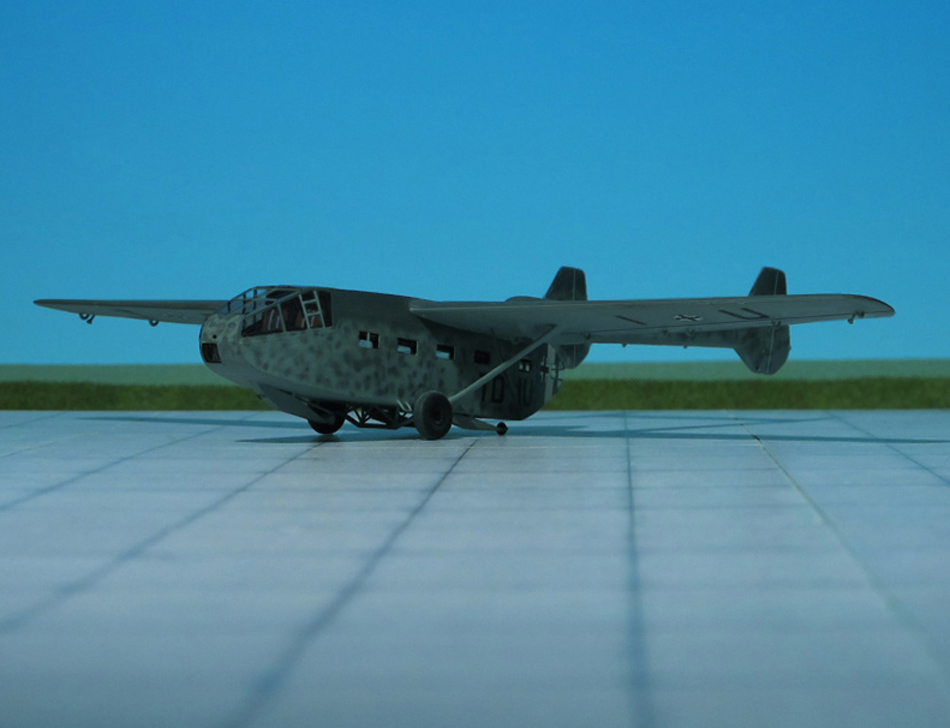
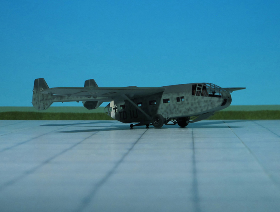
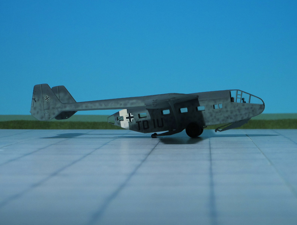
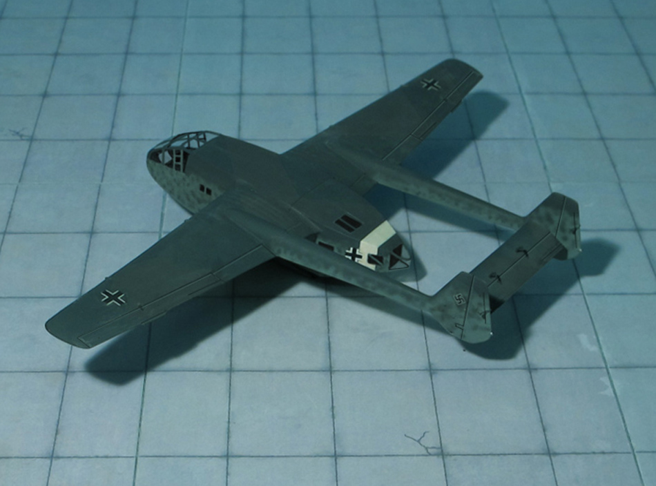
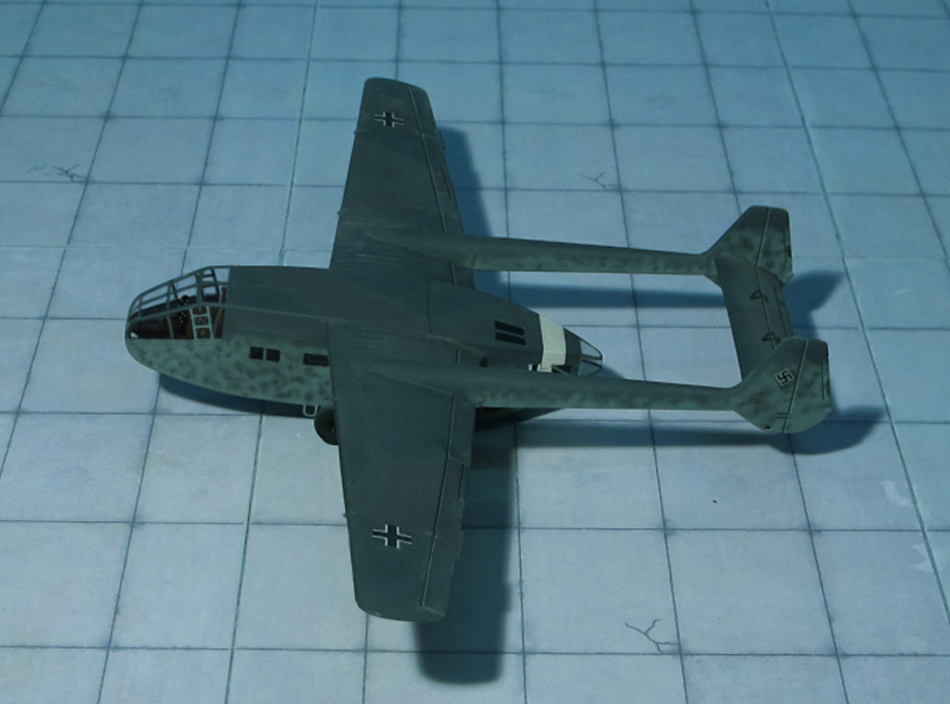
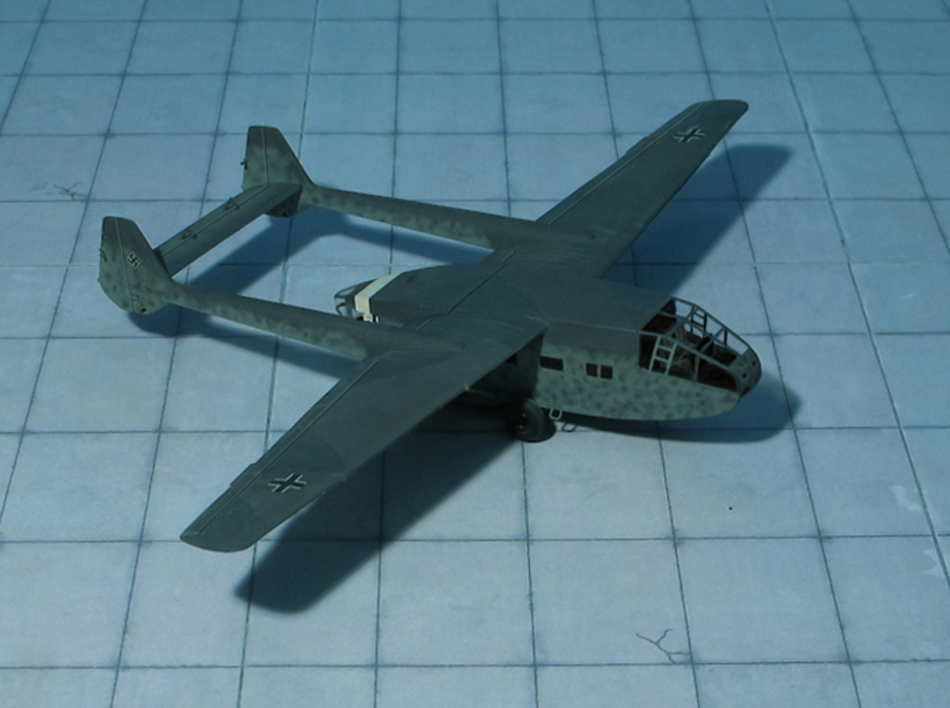
COMMENT: The Gotha Go 242 was designed in response to a ReichsLuftfahrt Ministerium (RLM) requirement for a heavy transport glider to replace the DFS 230 then in service. The requirement was for a glider capable of carrying 20 fully laden troops or the equivalent cargo.
The aircraft was a high-wing monoplane with a simple square-section fuselage ending in clamshell doors used to load cargo. The empennage was mounted on twin booms linked by a tail plane. The fuselage was formed of steel tubing covered with doped fabric. The flight characteristics of the design were better than those of the DFS 230. Cargo versions of the glider featured a hinged rear fuselage loading ramp that could accommodate a small vehicle such as a “Kübelwagen” (Jeep) or loads of similar size and weight.
Two prototypes flew in 1941 and the type quickly entered production. At the end of 1942 253 Gotha Go 242A-0 and A-1A have been delivered primarily used for freight transportation. For take-off a two wheel jettisonable landing gear and for landing three landing skids were provided. In total 1,259 Gotha Go 242A-0 and A-1 were produced.
In service, Go 242s were towed into the air by Heinkel He 111s or Junkers Ju 52s. Most saw service in the Mediterranean, North Africa, and Aegean. Occasionally, Junkers Ju 87D-2 were used as tow plane. These had strengthened rear fuselage and combined tailwheel and hook for towing the Gotha Go 242.
Furthermore, the glider was tested with rockets for overloaded take offs. A jettisonable rack of four 48 kg Rheinmetall RI 502 solid fuel rockets each developing at 153 kp thrust for six seconds was attached to the rear of the cargo compartment. These were ignited in sequence to provide a continuous 153 kp thrust for 24 seconds.
A second rocket assisted system called the “R” (Rauch) Gerät (“Smoke” Decice) was also used with the glider. This was a liquid-fuel Walter KG R I-203 (HWK 500A) “Starthilfe” (Take-off Assist) monopropellant, RATO podded rocket engine which was mounted beneath the wing on either side of the body and was jettisoned after takeoff, parachuting down to be recycled (Ref.: 24).
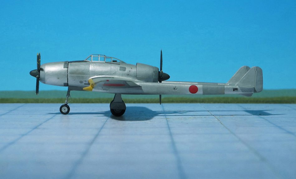
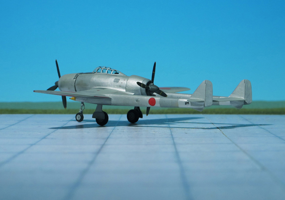
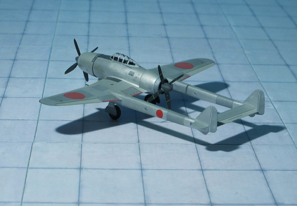
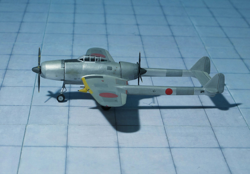
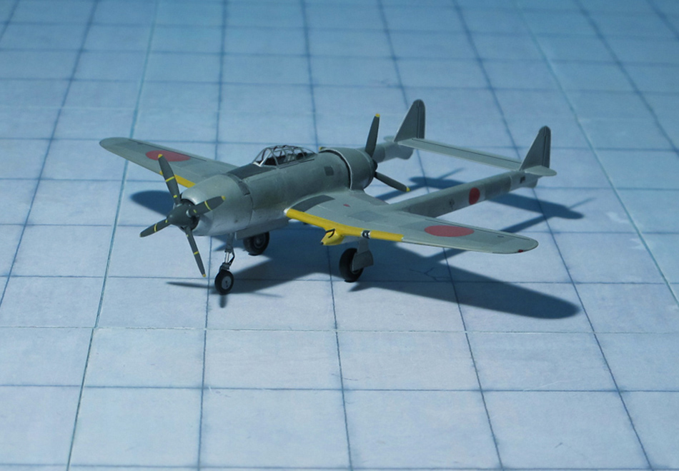
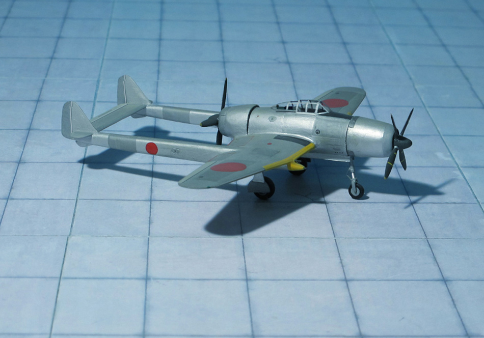
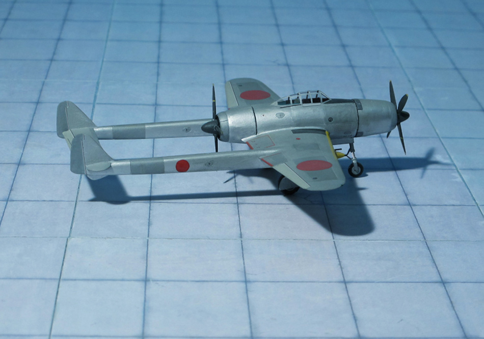
POWER PLANT: One Mitsubishi Ha-211 Ru radial engine, rated at 2,200 hp
PERFORMANCE: 485 mph at 32,810 ft (estimated)
COMMENT: Preliminary discussions regarding a heavily armed high-altitude fighter were held between the Koku Hombu and Tachikawa Hikoki K. K. in mid-1942. The new aircraft was to be fitted with a pressure cabin and capable of reaching a top speed of 490 mph. The aircraft proposed by Tachikawa, which received the Kita designation Ki-94, was of a highly unconventional design. The aircraft was a large twin-boom monoplane, powered by two 2,200 hp Mitsubishi Ha-211 Ru air-cooled radials which were mounted fore and aft of the pilot’s cockpit and drove four-blade tractor and pusher propellers. The very heavy armament that should have been mounted on the aircraft should have been powerful enough to make short work of most US heavy bombers of that area at that time. A full-scale wooden mock-up of the Ki-94 was ordered and built although at the same time a contract was placed with Nakajima for another high-altitude fighter, the Ki- 87, with less stringent range requirements as a fall-back design for the Tachikawa Ki-94.
Notwithstanding the outstanding prospective performance, which however was judged by the technical department of the Japanese Army Air Force as “unduly optimistic” and too complex, the design was discarded. But in mid-1943 Tachikawa submitted a new proposal to meet the same requirements as the competitive Nakajima Ki-87. In order to avoid confusion the Kitai designation the first Tachikawa design received the designation Ki-94-I, and the new design Ki-94-II (Ref.: 1, 24).
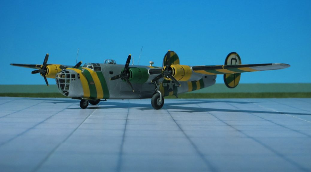
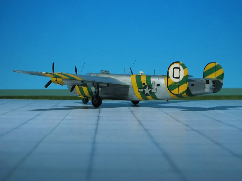
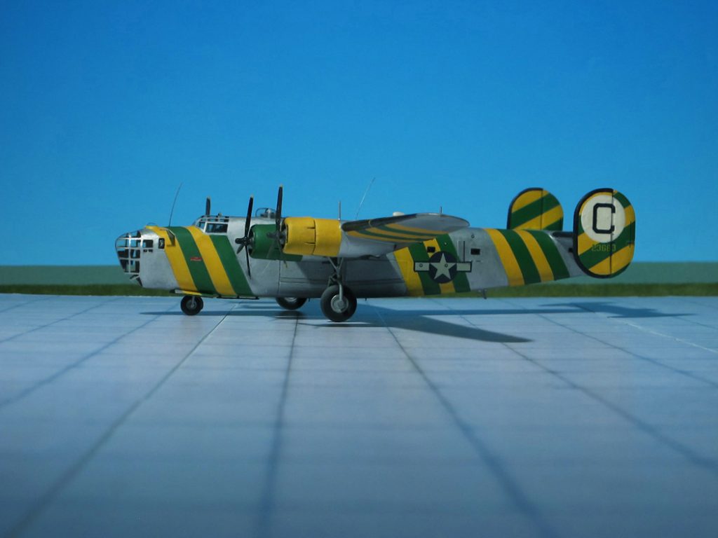
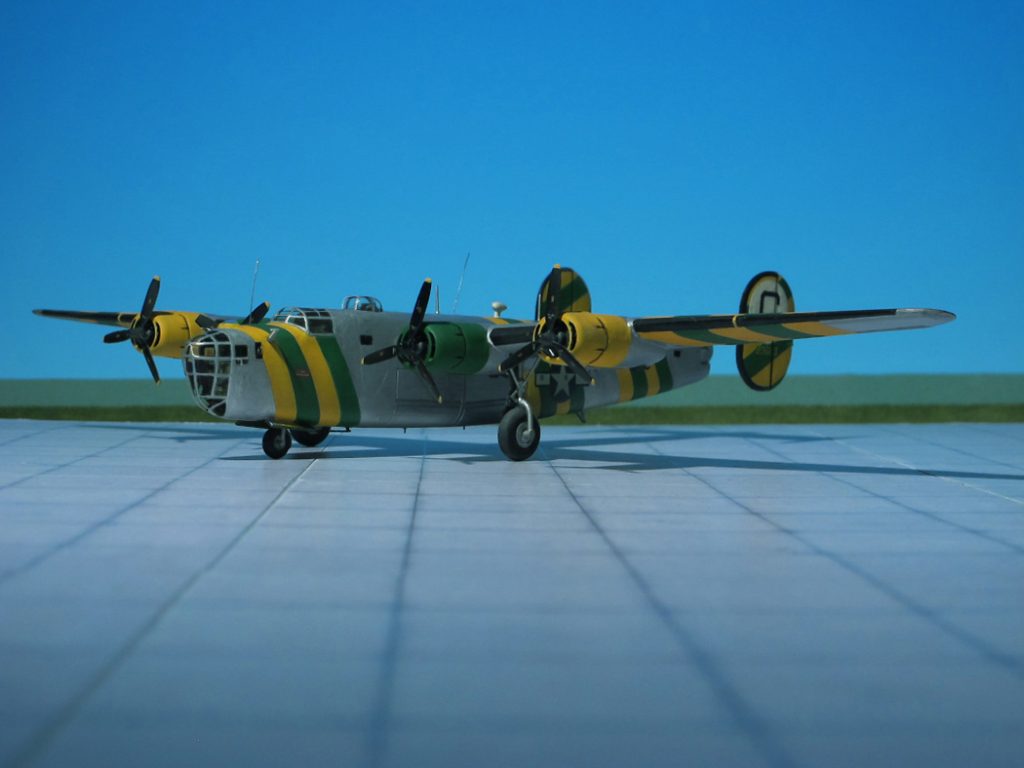
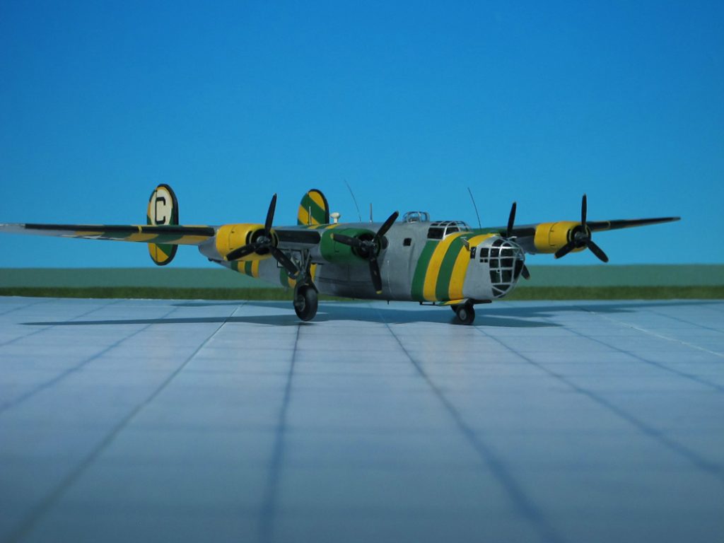
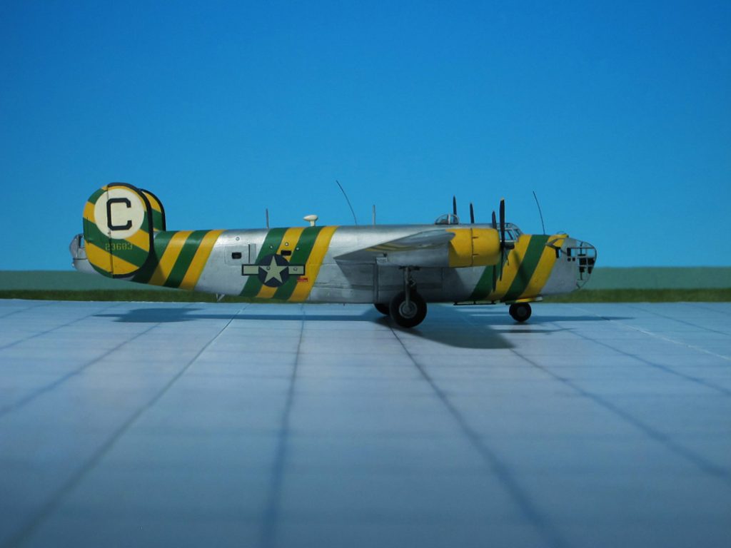
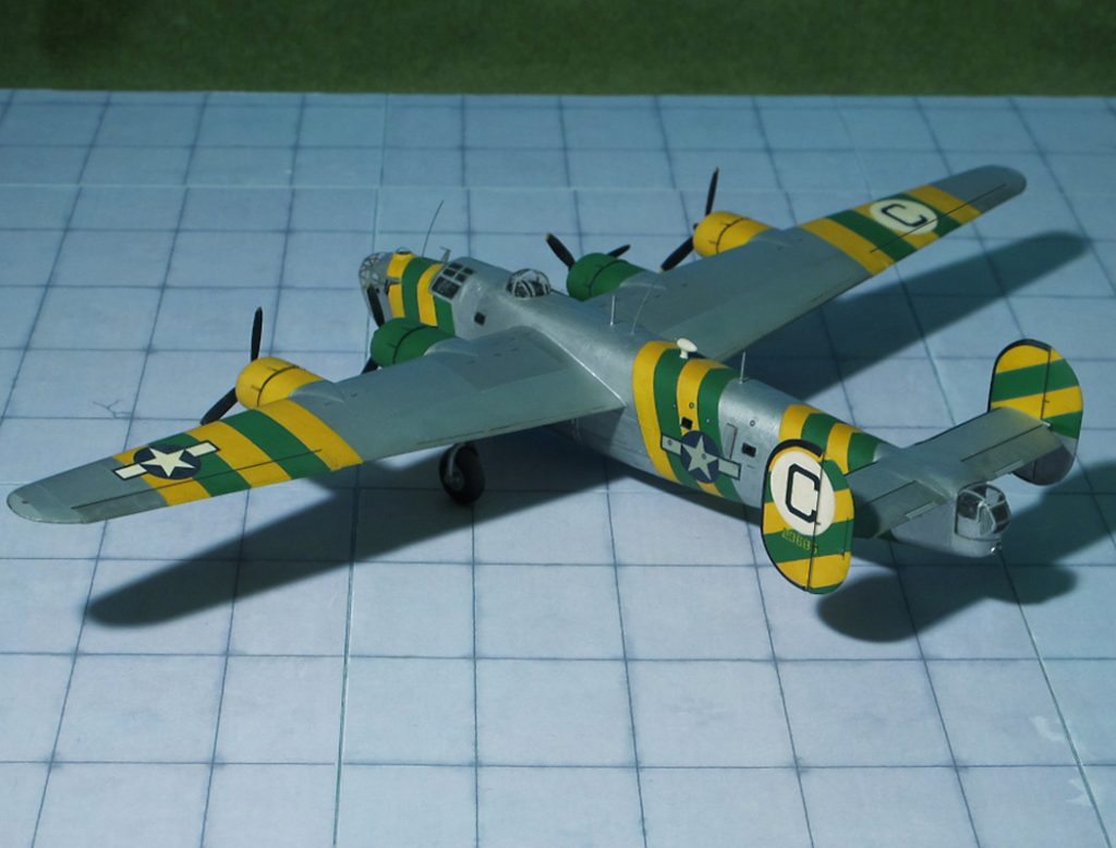
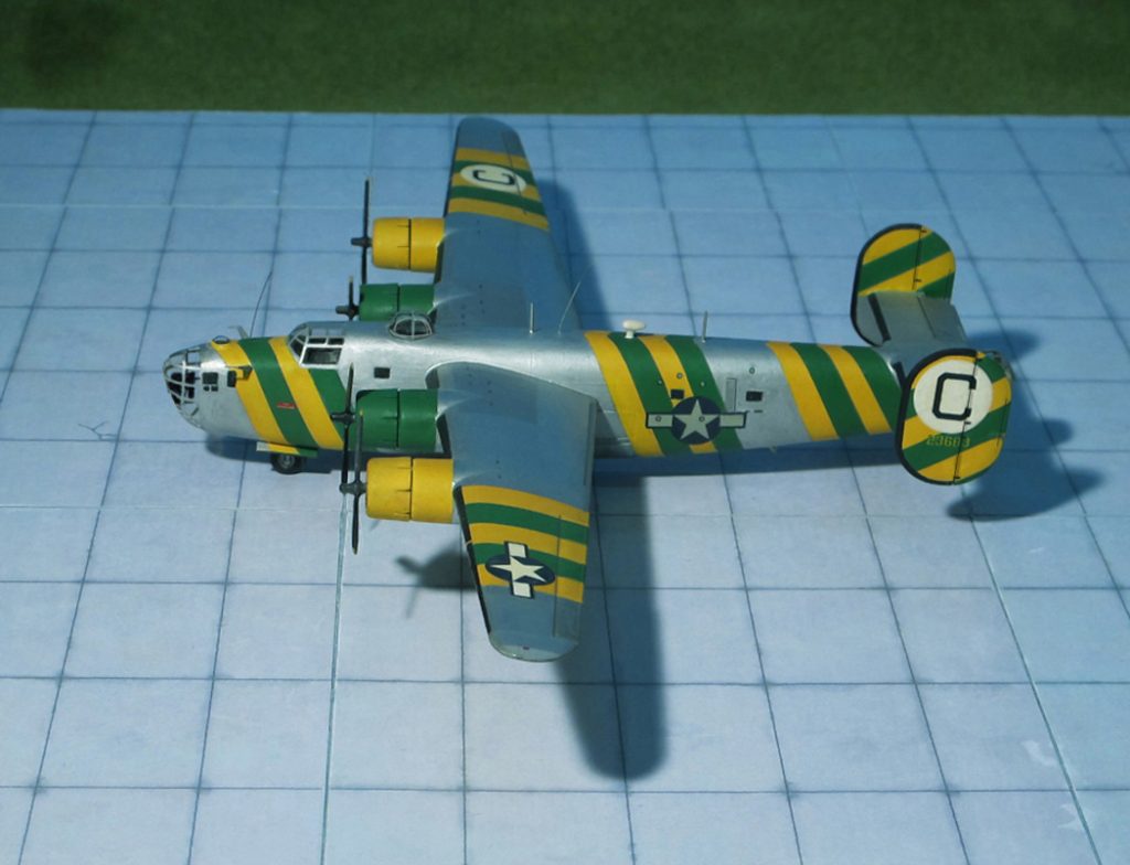
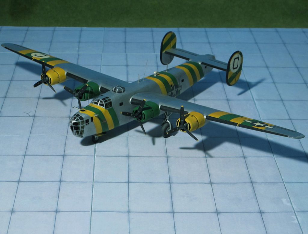
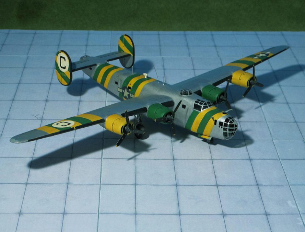
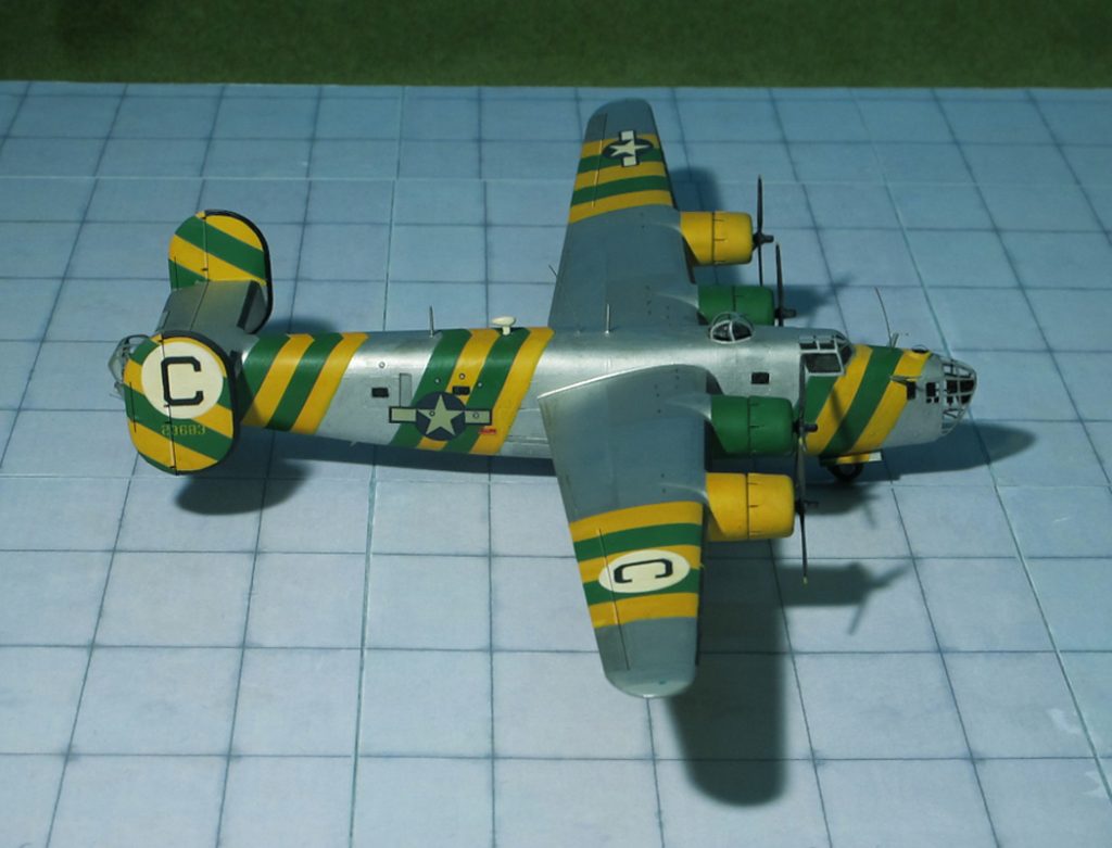
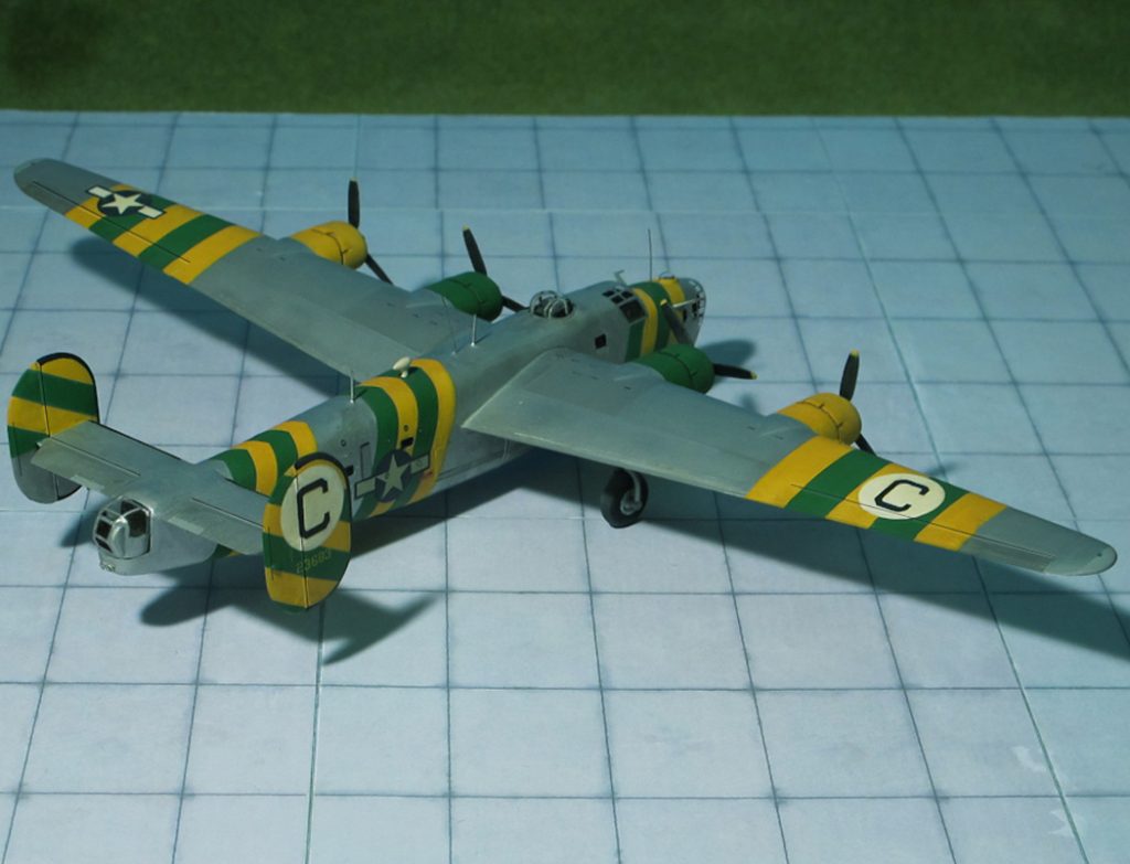
TYPE: Heavy long-range bomber, in service as Assembly ship
ACCOMMODATION: Crew of five to six
POWER PLANT: Four Pratt & Whitney R-1830-35 turbocharged “Twin-Wasp” radial engines, rated at 1.200 hp each
PERFORMANCE: 290 mph
COMMENT: In February 1944, the 2nd Division of the Eight Army Air Force in Europe authorized the use of “Assembly Ships” (or “Formation Ships”) specially fitted to aid assembly of individual group formations. They were equipped with signal lighting, provision for quantity discharge of pyrotechnics, and were painted with distinctive group-specific high-contrast patterns of stripes, checkers or polka dots to enable easy recognition by their flock of bombers. The aircraft used in the first allocation were B-24Ds retired by the 44th, 93rd and 389th Groups. Arrangements for signal lighting varied from group to group, but generally consisted of white flashing lamps on both sides of the fuselage arranged to form the identification letter of the group. All armament and armor was removed and in some cases the tail turret. In the B-24Hs used for this purpose, the nose turret was removed and replaced by a “carpetbagger” type nose. Following incidents when flare guns were accidentally discharged inside the rear fuselage, some assembly (formation) ships had pyrotechnic guns fixed through the fuselage sides. As these aircraft normally returned to base once a formation had been established, a skeleton crew of two pilots, navigator, radio operator and one or two flare discharge operators were carried. In some groups an observer officer flew in the tail position to monitor the formation. These aircraft became known as „”Judas goats“ (Ref: 24).
The Consolidated B-24D “Liberator”, 41-23683 “Green Dragon” shown here is an assembly (formation-) ship of the 458th Bombardment Group (H) “The Sky Scorpions”, 8th USAAF, stationed at Hethel, UK from 1943 to 1945 (Ref.: 2)
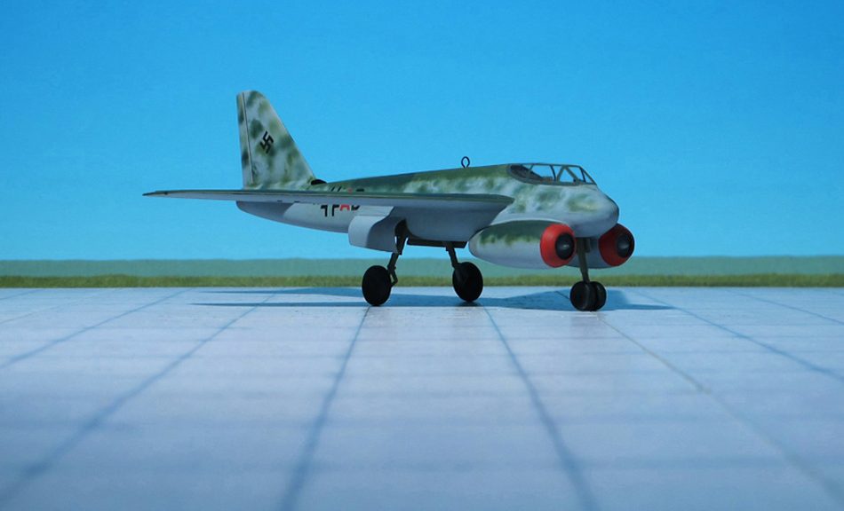
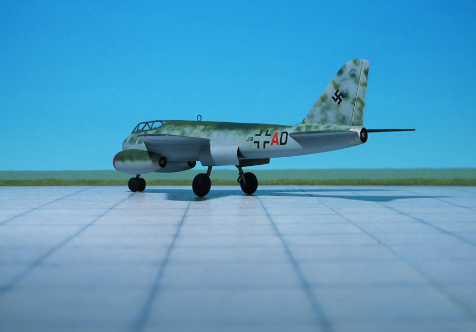
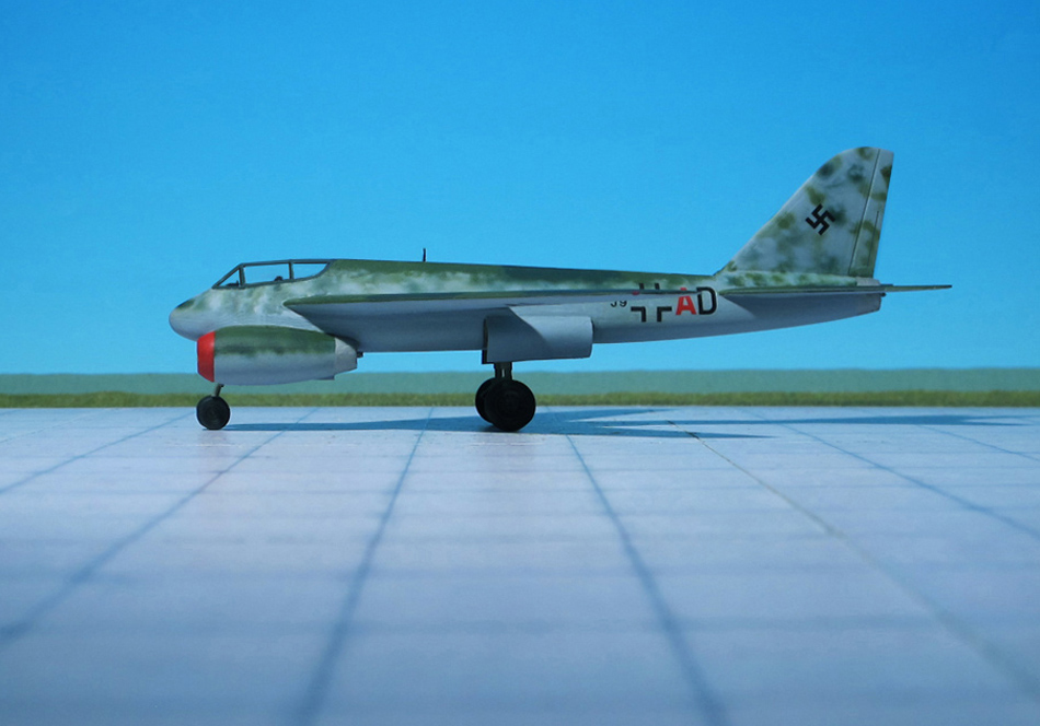
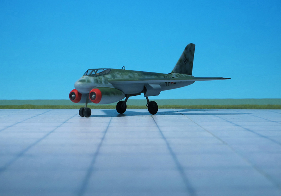
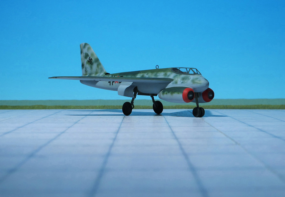
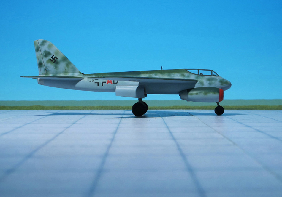
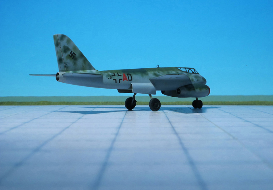
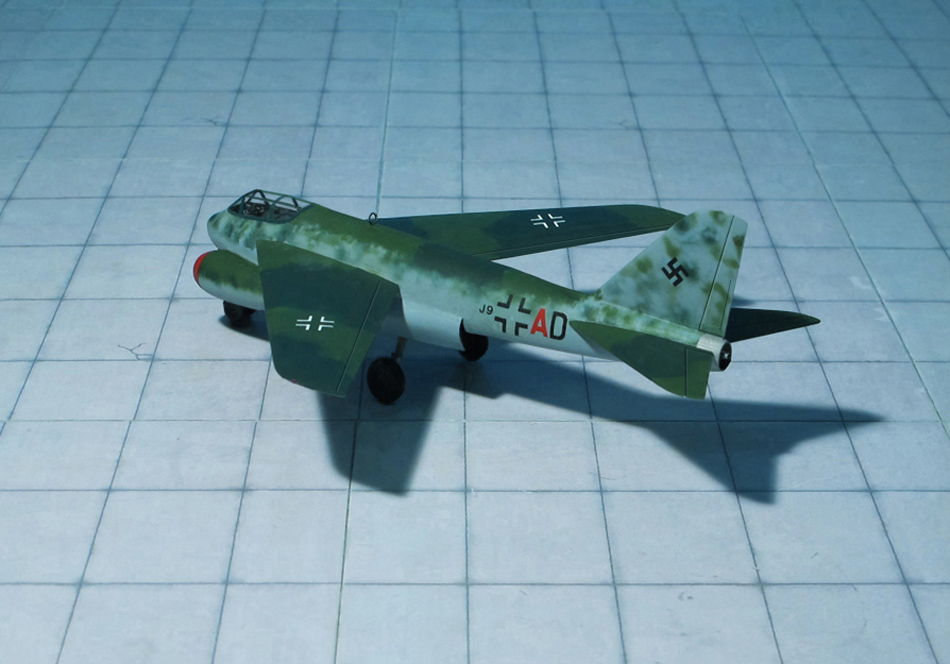
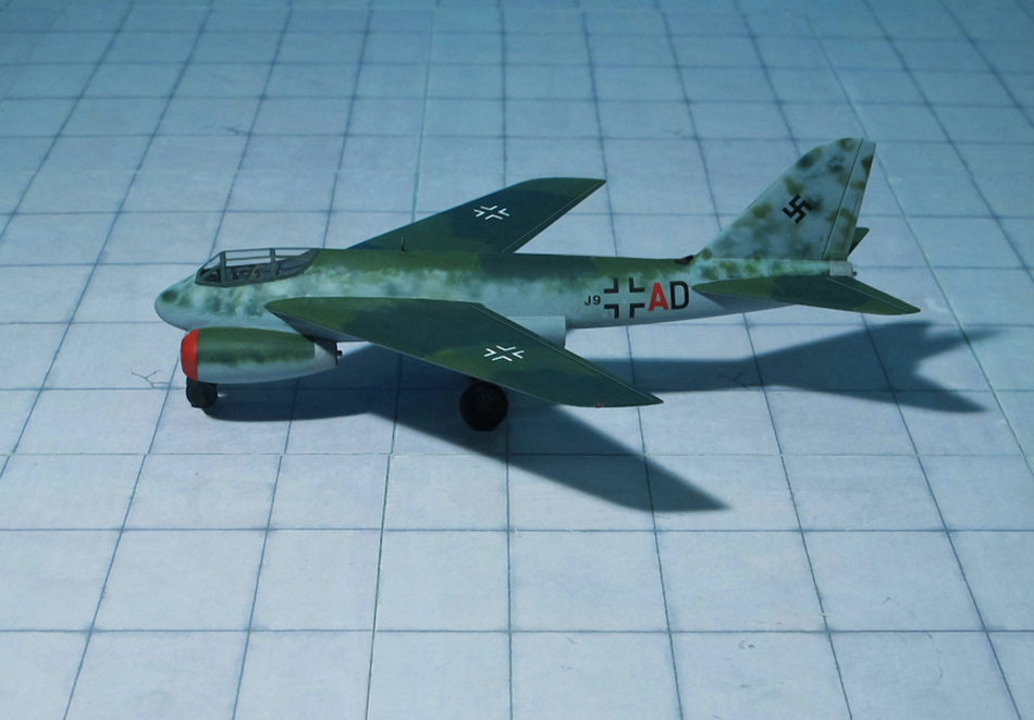
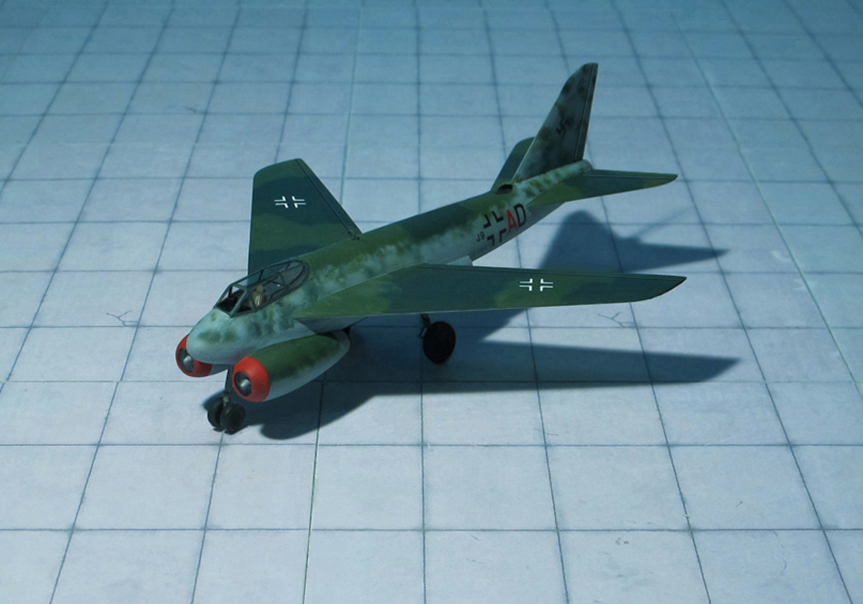
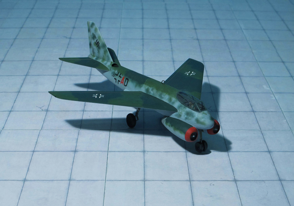
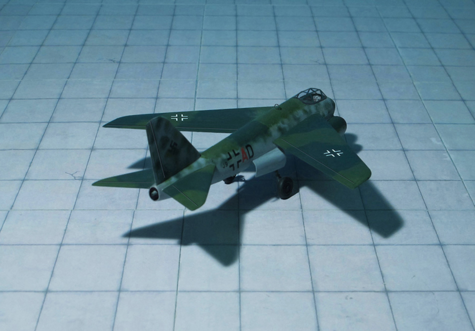
POWER PLANT: Three Heinkel-Hirth HeS 011 turbojet engines, rated at 1,200 kp each
PERFORMANCE: 627 mph
COMMENT: During the summer of 1944, the Messerschmitt Me P.1102/105 project was on the drawing board at the same time as the Me P.1101 projects were designed, e. g. Me P.1101/92, Me P.1101/99 and Me P.1101/101. Several of these projects were of variable-geometry wing designs, a configuration which was a novelty in aircraft designing at that time.
The Messerschmitt Me P.1102/105 was developed as a fast bomber and heavy fighter.The variable-sweep wings were mounted in the center of the fuselage and could be swept between 15 and 50 degrees. For take-off and landing the wings were to be set at 20 degrees and for high speed flight the wings were to be set at the maximum of 50 degrees. The tail unit was of a normal configuration, with the tail planes swept back at 60 degrees.
Three jet engines powered the Me P.1102/105, two were located beneath the fuselage nose and one was located in the tail with an air intake on the top of the rear fuselage to feed this turbojet. Either three BMW 003 or Heinkel-Hirth He S 011 jet engines were to be employed. A single pilot sat in a cockpit located in the forward fuselage and three fuel tanks of 1200 liter capacity each were located behind the cockpit. The lower fuselage held an internal bomb bay and the tricycle landing gear.
The collapse of Germany ended work on this design. All Messerschmitt documentation relating to this projects series was seized by the US and was used in the development of several post-war aircraft. The Messerschmitt Me P.1102/105 project’s unusual three-engine power plant arrangement, in particular, was employed on the Martin XB-51 high-speed attack-interceptor which first flew in mid-1949 (Ref.: 17).
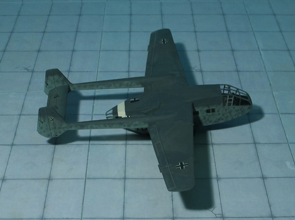
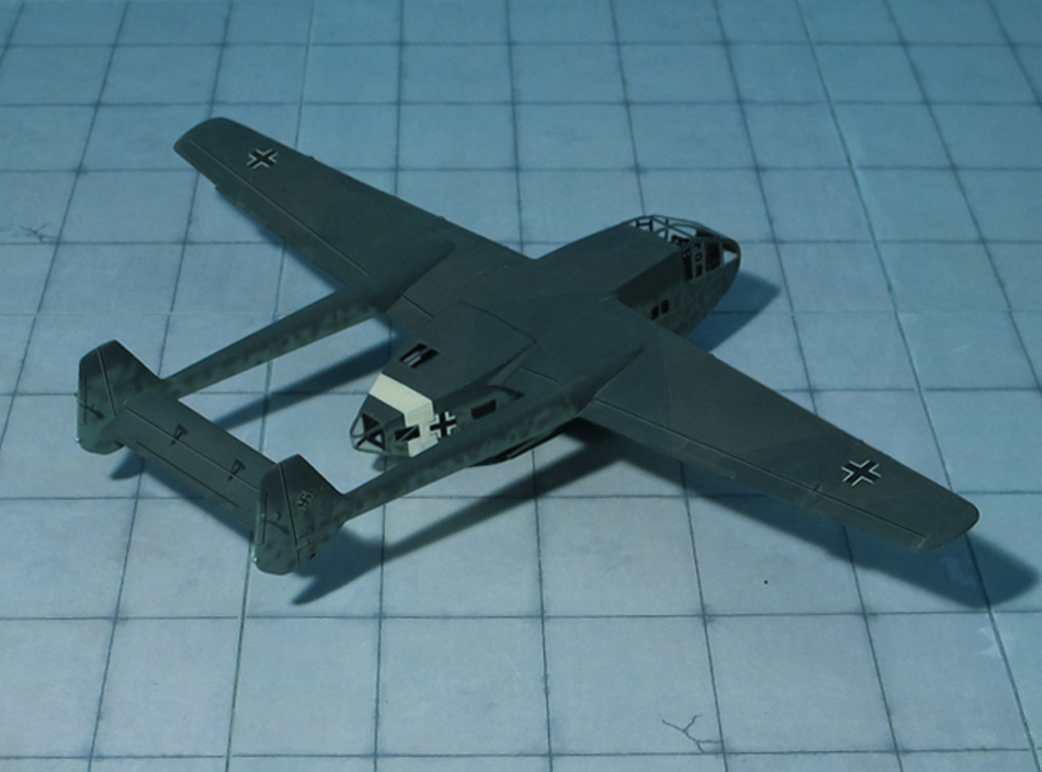
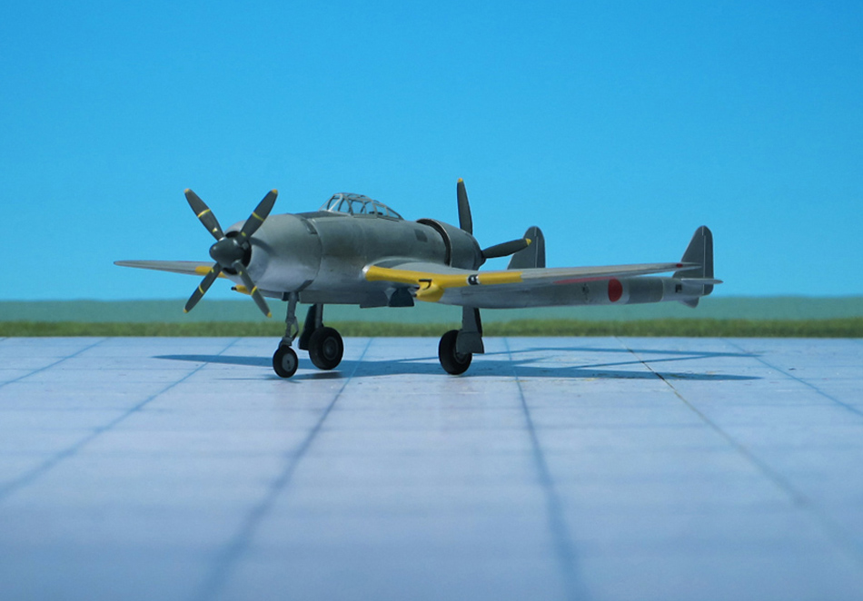
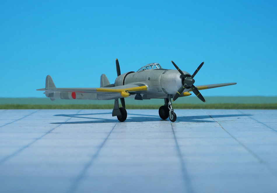
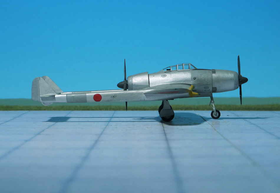
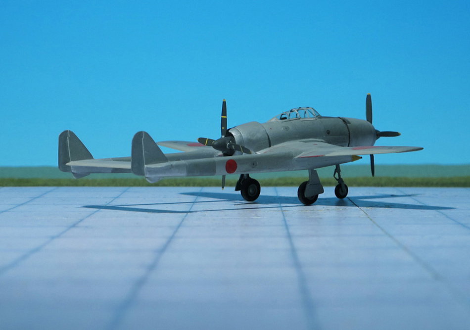
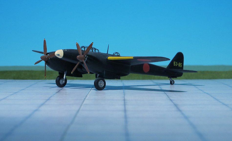
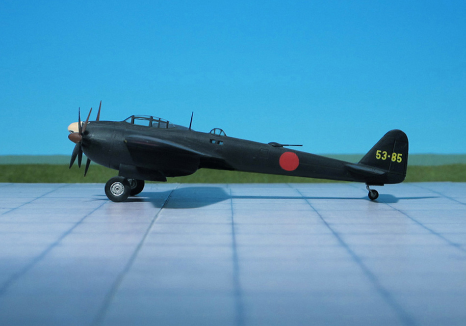
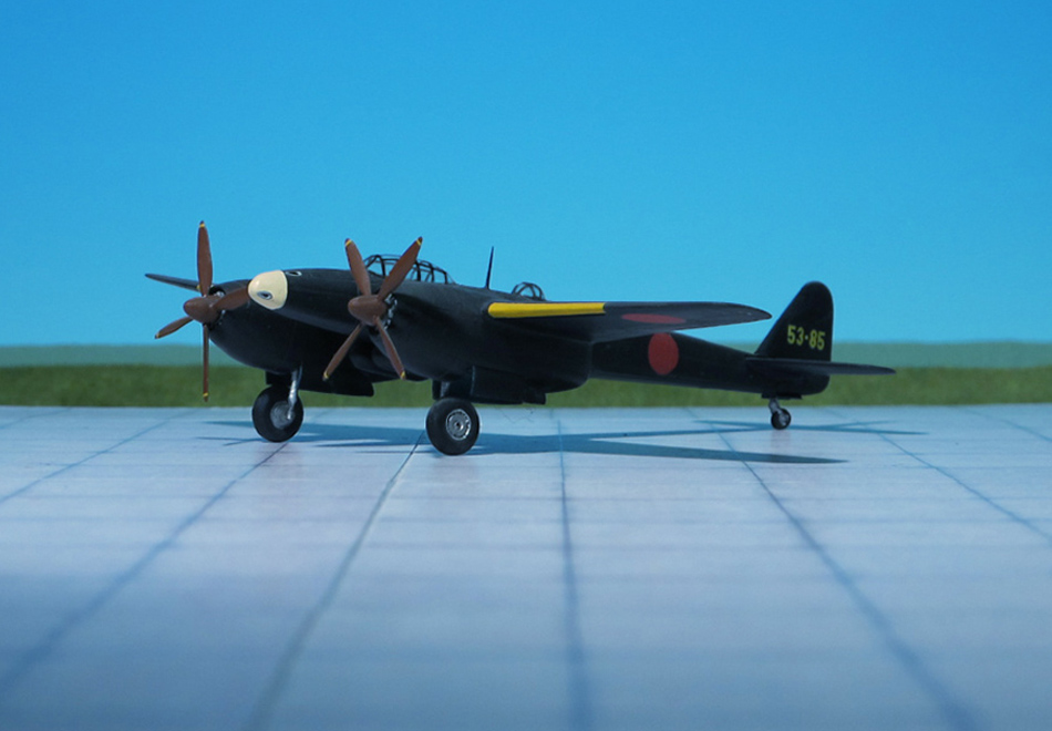
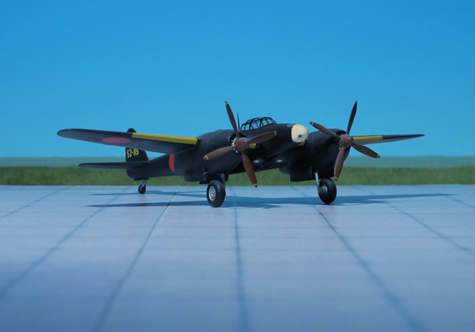
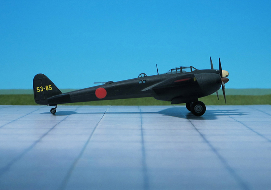
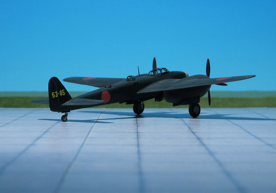
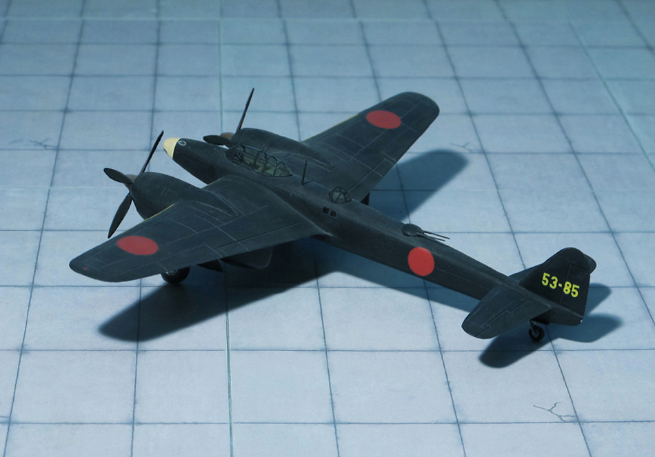
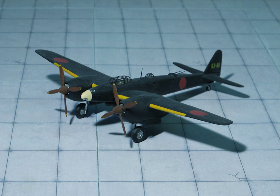
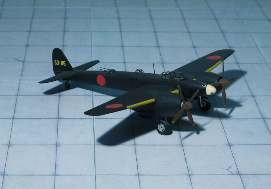
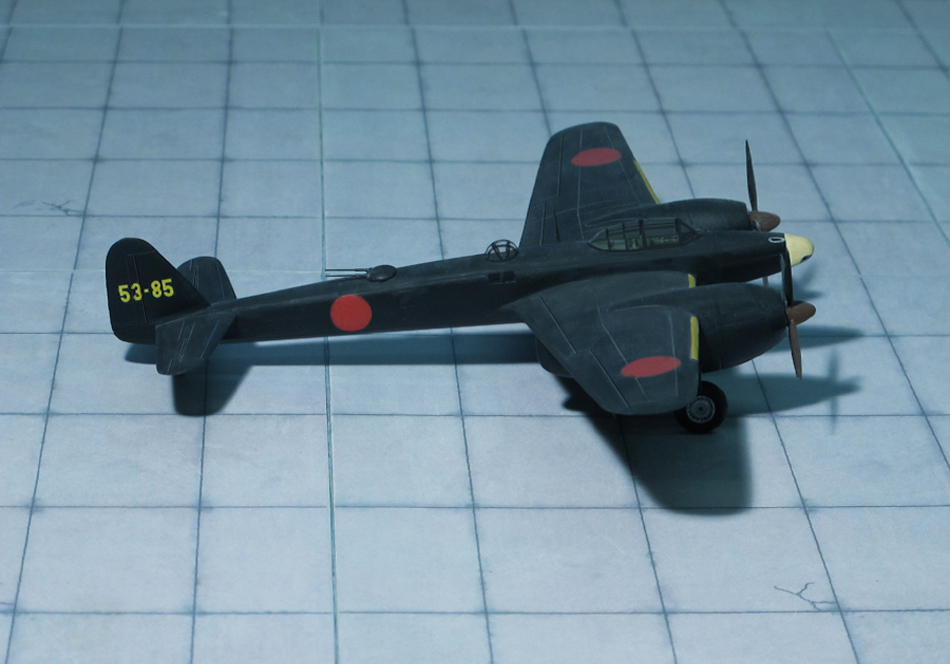
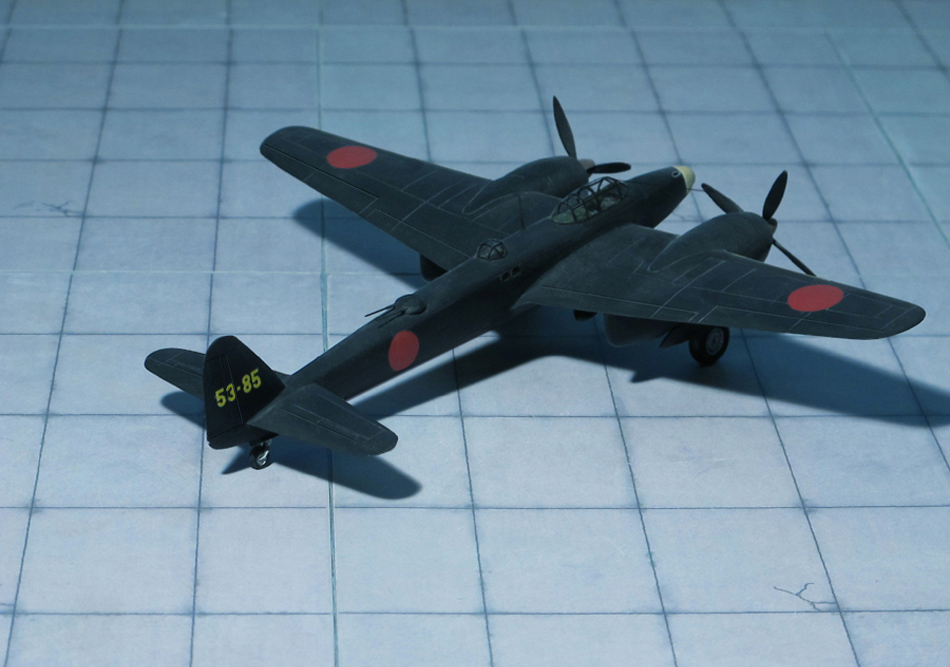
POWER PLANT: Two Nakajima NK9K-s radial engines, rated at 2,000 hp each
PERFORMANCE: 360 mph
COMMENT: The Aichi S1A “Denko” (“Bolt of Light”) was a Japanese night fighter, intended to replace the Nakajima J1N1-S “Gekko” (“Moonlight”, Allied code name “Irving”). It was to be, like the “Gekko”, equipped with radar to counter the B-29 air raids over the Japan. Development time increased while trying to overcome design shortcomings, such as the insufficient power of the Navy’s requested Nakajima “Homare” engines, resulting in no aircraft being completed before the war ended.
Because it was full of special equipment the “Denko’s” service weight exceeded ten thousand kilograms. Some of this specialized equipment included oxygen injection but the turbocharger’s remote location from the engine caused many problems. Because the initial prototypes’ engines did not pass Navy standards only two were ever manufactured. Two more had been planned before cancellation that would have used the more powerful Mitsubishi HI MK9A Ru or MK10A Ru engines.
Additionally, Tonokai earthquake occurred in December 1944 and the aircraft factories and prototypes were badly damaged. On 1945 June 9 the airstrikes on Aichi Kokuki KK and Aichi Tokei Denki Seizo Co, Ltd blew up the first prototype and forced movement of the second to the Gifu large Sadakazu factory to be assembled. But on July 9 of that year another airstrike destroyed the second prototype. At that time Aichi S1A “Denko” was the most massive fighter developed in Japan’s naval history (Ref.: 24).
Aichi S1A1 “Denko” (“Bolt of Light”)
Aichi S1A1 “Denko” (“Bolt of Light”)
Aichi S1A1 “Denko” (“Bolt of Light”)
Aichi S1A1 “Denko” (“Bolt of Light”)
Aichi S1A1 “Denko” (“Bolt of Light”)
Aichi S1A1 “Denko” (“Bolt of Light”)
Aichi S1A1 “Denko” (“Bolt of Light”)
Aichi S1A1 “Denko” (“Bolt of Light”)
Aichi S1A1 “Denko” (“Bolt of Light”)
Aichi S1A1 “Denko” (“Bolt of Light”)
Aichi S1A1 “Denko” (“Bolt of Light”)
Aichi S1A1 “Denko” (“Bolt of Light”)
Aichi S1A1 “Denko” (“Bolt of Light”)
Scale 1:72 aircraft models of World War II
Mit der weiteren Nutzung unserer Webseite erklären Sie sich damit einverstanden, dass wir Cookies verwenden um Ihnen die Nutzerfreundlichkeit dieser Webseite zu verbessern. Weitere Informationen zum Datenschutz finden Sie in unserer Datenschutzerklärung.