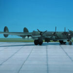
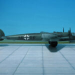
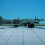
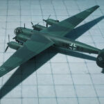
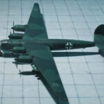
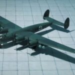
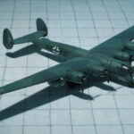
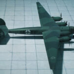
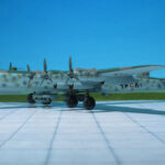
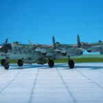
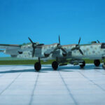
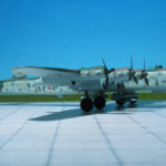
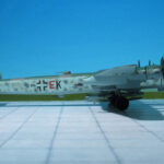
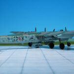
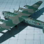
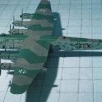
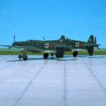
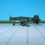
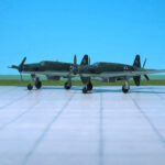
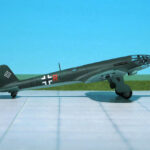
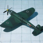
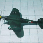
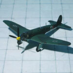
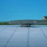
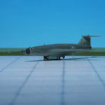
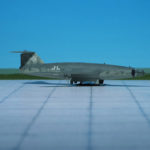
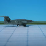
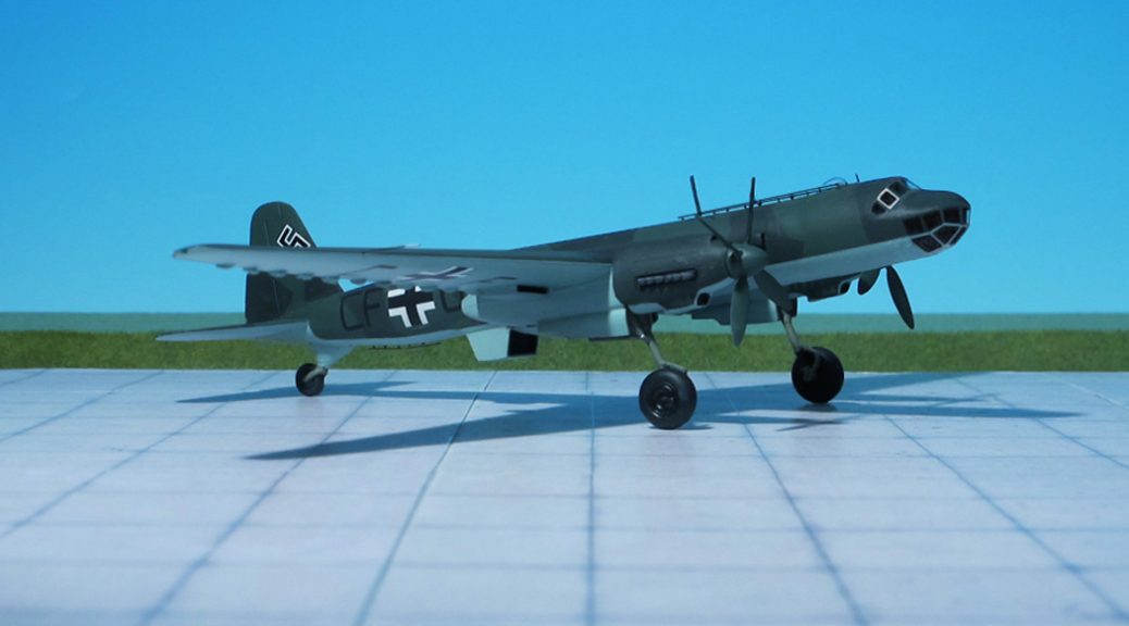
TYPE: Heavy bomber, Long-range reconnaissance aircraft
ACCOMMODATION: Crew of nine
POWER PLANT: Six BMW 801D radial engines, rated at 1,700 hp each plus two Junkers Jumo 004 turbojet engines, rated at 900 kp thrust each
PERFORMANCE: 450 mph (estimated)
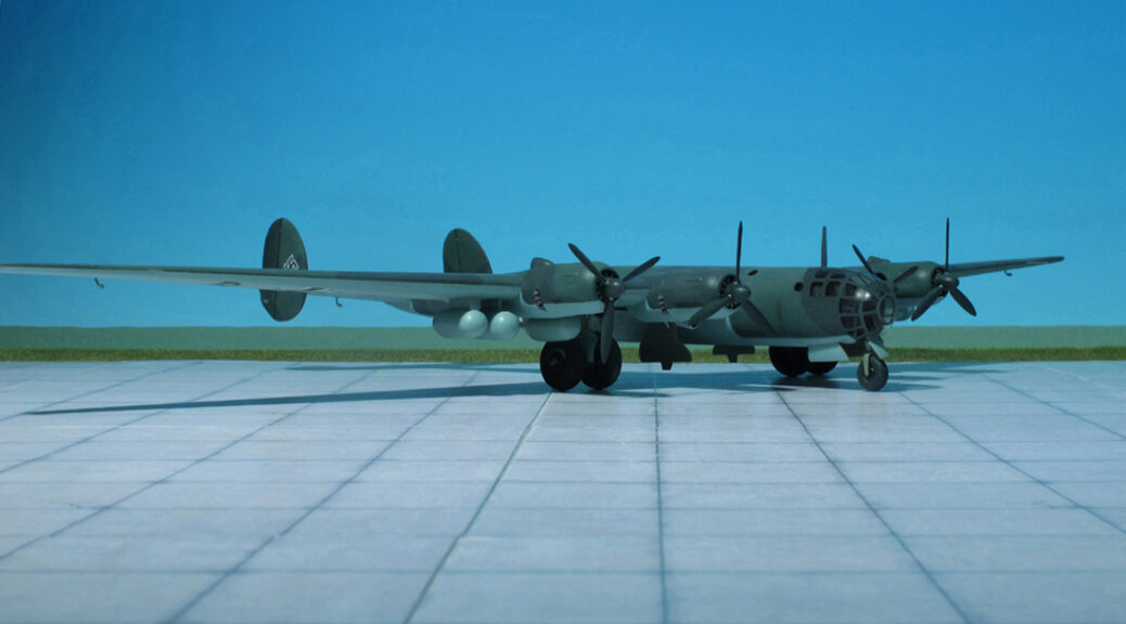
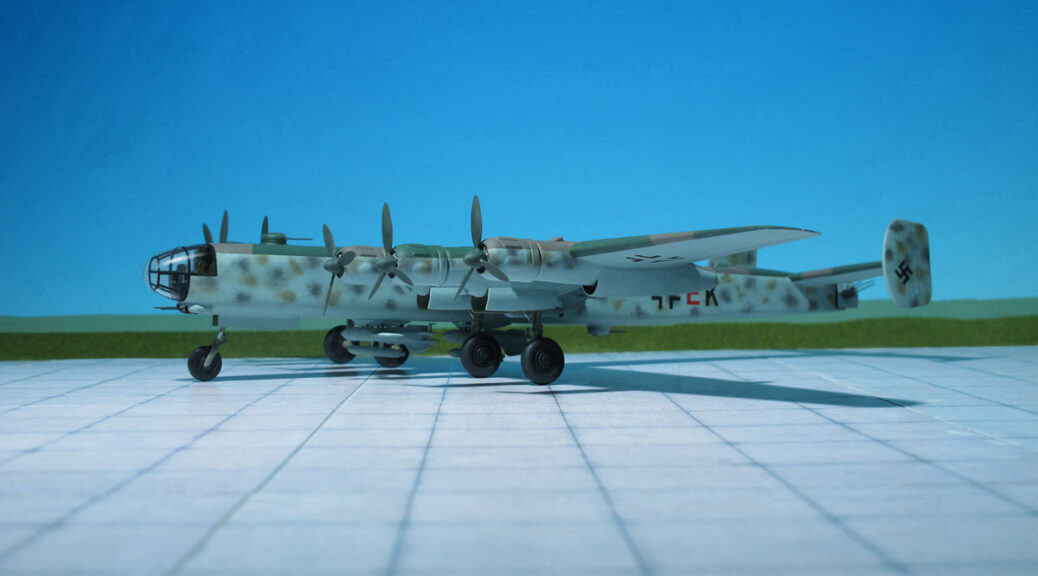
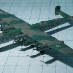
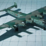
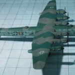
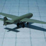
COMMENT: The Focke-Wulf Ta 400 was a large six-engined heavy bomber design developed in Nazi Germany in 1943 by Focke Wulf Aircraft Company as a serious contender for the Amerika Bomber project. One of the first aircraft to be developed from components from multiple countries, it was also one of the most advanced Focke Wulf designs of World War II, though it never progressed beyond a wind tunnel model.
In response to the RLM guidelines of January 1942, Kurt Tank of the Focke-Wulf company designed the Ta 400 as a bomber and long-range reconnaissance aircraft, to be powered by six BMW 801D radial engines, to which two Junkers Jumo 004 turbojet engines were later added. Design work was begun in 1943, much of it being carried out by French technicians working for Focke-Wulf at the Arsenal de l’Aéronautique at Chatillon-sous-Bagneux near Paris, with contracts for design and construction of major components being awarded to German, French, and Italian companies in an attempt to speed the process and begin construction of prototypes as soon as possible.
The Ta 400 had a shoulder-mounted wing with 4° dihedral, with a long straight center section extending to the middle engine on each wing, and highly tapered outer wing panels. It had twin vertical stabilizers mounted at the tips of the tailplane. Like the American Boeing B-29 Superfortress, the Ta 400 was to have a pressurized crew compartment and tail turret, connected by pressurized tunnel, as well as multiple remote-controlled turrets. The crew was to be protected by a heavy defensive armament, including ten 20 mm MG 151 cannons; and the same Hecklafette quadmount tail-turret with two MG 131 machine guns, as the later model Heinkel He 177A series aircraft and Heinkel He 177B bombers would have used. Fuel supply was to have distributed across 32 fuel tanks. Another design feature was tricycle landing gear.
The maximum bomb load was to have been 24 t. With a gross weight of 80.27 tonnes, the Ta 400 with Daimler Benz DB 603 engines was estimated to have a range of 7,500 mi in the reconnaissance role, cruising at 202 mph. The two bomber versions would have 76.07 tonnes and 80.87 tonnes gross weights with estimated ranges of 2,800 mi and 6,600 mi respectively. The projected Jumo-powered aircraft would have had a maximum range of 8,700 mi for long range reconnaissance and 8,100 mi as a bomber.
As with the Heinkel He 277 competitor for the Amerikabomber contract, no prototype of the Ta 400 was ever built It never progressed beyond a wind tunnel model, and performance, range and dimensions here are based solely on the designers’ estimates. The master aircraft designer Ernst Heinkel himself remarked in October 1943, while both designs were still being worked on, that he thought that only the Ta 400 could be a worthy competitor to his firm’s He 277, for the Amerika Bomber competition. The Ta 400 was essentially a backup design for the Messerschmitt Me 264. As the design required more materials and labor than the Me 264, the RLM became convinced that further development of the Ta 400 was a waste, and on October 1943 notified Focke-Wulf that the program would be terminated, but the minutes of a meeting in Italy between Tank and Italian aviation industrialists on April 1944 – just two days before the entire He 277 program was also cancelled – confirmed that work on the design was still ongoing and proposed the cooperation of Italian industry in the project (Ref.: 24).
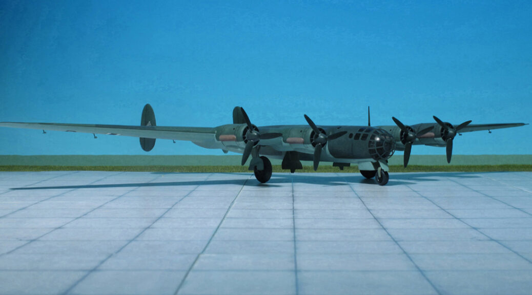
POWER PLANT: Four Junkers Jumo 211J inline engines, rated at 1340 hp each or four BMW 801G radial engines, rated at 1,750 hp each.
PERFORMANCE: 339 mph at 36,000 kg at 20,015 ft
COMMENT: The Messerschmitt Me 264 was a long-range strategic bomber developed during World War II for the German Luftwaffe as its main strategic bomber. The design was later selected as Messerschmitt‘s competitor in the RLM (Reichsluftfahrt-ministerium, German Air Ministry) Amerikabomber programme, for a strategic bomber capable of attacking New York City from bases in France or the Azores.
Three prototypes were built but production was abandoned to allow Messerschmitt to concentrate on fighter production and the Junkers Ju 390 was selected in its place. Development continued as a maritime reconnaissance aircraft instead.
The origin of the Me 264 design came from Messerschmitt’s long-rangereconnaissance aircraft project, the P.1061, of the late 1930s. A variant on the P.1061 was the P.1062 of which three prototypes were built, with only two “engines” to the P.1061’s four, but they were, in fact, the more powerful Daimler-Benz DB 606 “power systems”, each comprising a pair of DB 601 inverted V-12 engines. These were also successfully used in the long-range Messerschmitt Me 261, itself originating as the Messerschmitt P.1064 design of 1937. The DB 606’s later use in the Heinkel He 177A‘s airframe design resulted in derision by Reichsmarschall Hermann Göring as „welded-togehter engines in August 1942, due to badly designed engine installations. In early 1941, six P.1061 prototypes were ordered from Messerschmitt, under the designation Messerschmitt Me 264. This was later reduced to three prototypes.
The progress of these projects was initially slow, but after Germany had declared war on the United States four days after the Pearl Harbor attack by Imperial Japan, the Reichsluftfahrtministerium started the more serious Amerikabomberprogramme in the spring of 1942 for a very long range bomber, with the result that a larger, six-engine aircraft with a greater bomb load was called for. Proposals were put forward for the Junkers Ju 390, the Focke-Wulff Ta 400, a redesign of the unfinalized and unbuilt Heinkel He 277 design, and a design study for an extended-wingspan six-engine Messerschmitt Me 264B. The need for six engines was prompted by the ongoing inability of Germany’s aviation powerplant designers to create combat-reliable powerplants of 2,000 PS and above power output levels, thwarting efforts to do the same with just four engines instead. As the similarly six-engined Junkers Ju 390 could use components already in use for the Junkers Ju 290 this design was chosen.
The Me 264 was not abandoned, however, as the Kriegsmarine (German Navy) separately demanded a long-range maritime patrol and attack aircraft to replace the converted Focke-Wulf Fw 200 Condor in this role. As a result, the two pending prototypes were ordered to be completed as development prototypes for the Me 264A ultra long-range reconnaissance aircraft.
The Me 264 was an all-metal, high-wing, four-engine heavy bomber of classic construction. The fuselage was round in cross-section and had a cabin in a glazed nose, comprising a “stepless cockpit” with no separate windscreen section for the pilots, which was common for most later German bomber designs. A strikingly similar design was used for the Boeing B-29 Superfortress, of slightly earlier origin. The wing had a slightly swept leading edge and a straight trailing edge. The empennage had double tail fins. The undercarriage was a retractable tricycle gear with large-diameter wheels on the wing-mounted main gear. . In order to provide comfort on the proposed long-range missions, the Me 264 featured bunk beds and a small galley complete with hot plates.
The Me 264’s first prototype was originally fitted with four Junkers Jumo inverted V12 engines using the then-new Kraftei (or “power egg”) unitized powerplant installation as standardized for the earlier Junkers Ju 88A Schnellbomber, but inadequate power from the Jumo 211 engines led to their replacement on the Me 264 V1 first prototype with four similarly unitized 1,700 hp BMW 801G engines. The first prototype, the Me 264 V1, bearing the Stammkennzeichen factory code of RE+EN, was flown on 23 December 1942. It was powered at first by four Junkers Jumo 211J inline engines of 1,340 hp each. In late 1943, these were changed to the BMW 801G radial engines which delivered 1,750 hp each.
Trials showed numerous minor faults and handling was found to be difficult. One of the drawbacks was the very high wing loading of the Me 264 in fully loaded conditions at some 356 kg/m2. Comparable aircraft, such as the Boeing B-29 Superfortress with a wing loading of 337 kg/m2, the redesigned Heinkell He 277 at 334.6 kg/m2 and the Junkers Ju 390 at 209 kg/m2 had lower wing loadings. The relatively high wing loading caused poor climb performance, loss of manoeuvrability, stability and high take-off and landing speeds. The first prototype was not fitted with weapons or armour but the following two prototypes, the Me 264 V2 and V3 had armour for the engines, crew and gun positions. The Messerschmitt Me 264 V2 was built without defensive armament and vital equipment and the Me 264 V3 was to be armed and have the same armour.
In 1943, the Kriegsmarine withdrew their interest in the Me 264 in favour of the Ju 290 and the planned Ju 390. The Luftwaffe indicated preference for the unbuilt Focke Wulf Ta 400 and the Heinkel 277 as Amerikabomber candidates in May 1943, based on their performance estimates. Further payments for development work to Messerschmitt AG for its design were stopped. Late in 1943, the second prototype, Me 264 V2, was destroyed in a bombing attack. On 18 July 1944, the first prototype, which had entered service with Transportstaffel 5, was damaged during an Allied bombing bombing raid and was not repaired. The third prototype, which was unfinished, was destroyed during the same raid. In October 1943, further Me 264 development was stopped to concentrate on the development and production of the Messerschmitt Me 262 turbojet fighter-bomber.
Following the cancellation of the competing He 277 in April 1944, on 23 September 1944, work on the Me 264 project was officially cancelled. Messerschmitt proposed a six-engine version of the Me 264, the Me 264/6m (or alternately Me 364), but it was never built (Ref.: 24).
POWER PLANT: Four Daimler-Benz DB 603E liquid-cooled engines, rated at 1,777 hp each
PERFORMANCE: 447 mph
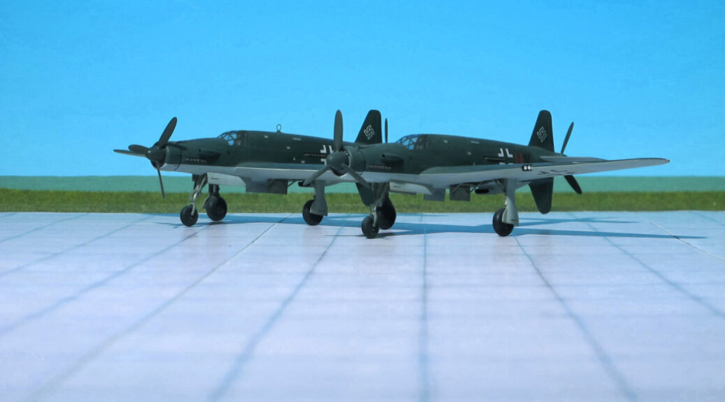
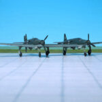
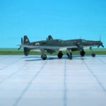
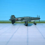
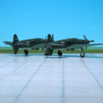
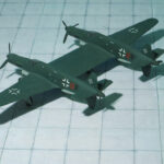
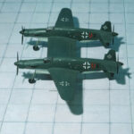
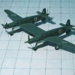
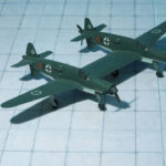
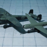
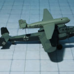
COMMENT: The Dornier Do 635 was a WW II long-range reconnaissance aircraft of the German Luftwaffe proposed by Dornier Company, as two Dornier Do 335 fuselages joined by a common center wing section.
In 1944, designers of Dornier Flugzeugwerke proposed the RLM a long-range reconnaissance aircraft with a range of 2.480 mi under the designation Dornier Do 335Z (Z for Zwilling ; “Twin”). Similar to the Heinkel He 111Z, a combination of two Heinkel He 111 bombers joined by a common center wing section, two Dornier Do 335B fuselages were connected by a center wing section. The pilot was seated in the left fuselage, the radio operator/navigator sitting in the right fuselage. Armament was not envisaged. The RLM confirmed the design provided the range was increased to app. 3.720 mi. Further modifications changed the design from the original Do 335 into a completely new aircraft; the new RLM designation was now Dornier Do 635. Four prototypes were ordered and begin of production was planned for June 1945.
On order of the RLM and representatives of the Luftwaffe the cooperation with Dornier was cancelled and all further development was transferred to Heinkel Flugzeugwerke.
Reason might be that Heinkel’s team had much experience with the Heinkel He 111Z and its twin fuselage combination. The designation of the project was internally changed to Heinkel He P.1070, officially Heinkel He 535 (or He 635, depending on literature). Again, profound changes were required. In order to increase range three external fuel tanks under the outer and center wings were provided, the wing span was reduced and the fuselage length was increased.
All these changes did not satisfy the RLM, so the design was revised again. The crew compartment was now solely positioned in the left fuselage and enlarged to seat three crew members: pilot, copilot and observer/navigator. Wing span was increased again, the center wing section was shortened to bring both fuselages closer together and the inner tail planes were provided as a common sector.
Meanwhile, a lot of time was wasted due to permanent changes in the requirements of the design. Finally, all further development was transferred to Junkers Flugzeugwerke. Prof. Hertel and his team refined the design once again, now under the designation Junkers Ju 635. The aim was to simplify the aircraft for easier production and an increase of range to app. 7.200 mi.
As its predecessor the Junkers design used two modified Dornier Do 335 fuselages, joined by a center wing section of constant chord, the outer wing panels were tapered back. Four Daimler-Benz DB 603E-1 engines supplied the power, one in each forward fuselage pulling and two in each rear fuselage driving a pusher propeller via a long drive shaft. Fuel was carried in ten internal wing tanks, four in the fuselages and possibly one in each fuselage bay. The port fuselage bay carried two Rb 50/30 cameras and the starboard bay contained five 60 kg marker bombs. A crew of three was envisioned, although this could be increased to four eventually. The pilot and the radio operator sat in the port fuselage and a second pilot sat in the starboard fuselage. The fourth crew member (navigator) was also to sit in the starboard fuselage. The landing gear was to consist of two nose wheels under each fuselage nose, two main wheels which were fitted with mud guards to protect the rear radiator intakes, and a jettisonable fifth wheel located beneath the center wing, which was fitted with a parachute for recovery. The main wheels were modified from the Junkers Ju 352 transports wheels. Two Walter HWK 109-500 RATO (Rocket Assisted Take Off) units could be fitted to assist take off. No armament was included due to the fact that this was a long-range reconnaissance aircraft and thus all weight was reserved for fuel and speed.
Four prototypes and six preproduction aircraft were orderd, the first example planned to take-off on February 1945. By early 1945, wind-tunnel models had been tested and cockpit mockups had been constructed. But by February 1945 due to the worsening war situation all further work on the Junkers Ju 635 was stopped.
The model shown here is the first design of the Dornier Do 635 (Ref.: 17, 24).
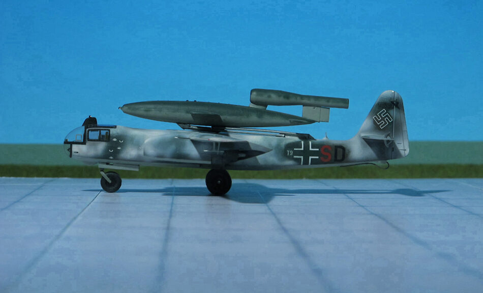
TYPE: Turbojet driven bomber, Mistel (Mistletoe) component ACCOMMODATION: Pilot only POWER PLANT: Four BMW 003A-2 turbojet engines, rated at 800 kp thrust each PERFORMANCE: 460 mph at 20,000 ft COMMENT: The Arado Ar 234 Blitz (Lightning) was the world’s first operational turbojet-powered bomber, built by the German Arado company during World War II.
Produced in limited numbers it was used almost entirely for aerial reconnaissance. In its few uses as a bomber it proved to be nearly impossible to intercept. It was the last German Luftwaffe aircraft to fly over the UK during the war, in April 1945
The Ar 234 was built in various versions: Ar 234A with two turbojet engines, Ar 234B with two turbojet engines or for engines in separat nacelles and Ar 234C with four engines mounted in a pair of twin-engine nacelles and a purely rocket-engine-driven Ar 234R. Of each of these various versions sub-types were built or planned.
The Arado Ar 234C was equipped with four lighter weight BMW 003A turbojet engines mounted in a pair of twin-engine nacelles based on basis of the eighth prototype. The primary reason for changing the engienes was to free up the Junkers Jumo 004 turbojets for use by the Messerschmitt Me 262, but the change improved overall thrust to nearly 3.2 tonnes with all four BMW turbojets at full take-off power, especially useful for take-off and climb-to-altitude performance. An improved cockpit design, with a slightly bulged outline for the upper contour integrating a swept-back fairing for the periscope, used a simplified window design with fewer glazed panels for ease of production. The four BMW jet engines gave about 20% greater airspeed than the Ar 234B series airframes, and the faster climb to altitude meant more efficient flight and increased range.
Although an operational test squadron was being prepared, only 14 C-series airframes had been completed by the end of the war, of which fewer than half had engines. Some were found at the end of the war sitting in the open, complete but for empty engine nacelles.Comprehensive flight testing of the new sub-type had yet to begin when Germany surrendered. Three basic variants of the C-series were planned for initial construction, with several more laid out as detailed proposals. Some of these would have had a pair of the higher thrust, but heavier Heinkel/Hirth HeS 011turbojet engines, while others were intended to feature swept or “crescent”-type wings.
There were plans, not put into practice, to use the Arado 234C turbojet bomber to launch V-1s either by towing them aloft or by launching them from a “piggy back” position (in the manner of the Mistel (Mistletoe), but in reverse) atop the aircraft. In the latter configuration, a pilot-controlled, hydraulically operated dorsal trapeze mechanism would elevate the missile on the trapeze’s launch cradle about 2.4 m clear of the Ar 234’s upper fuselage. This was necessary to avoid damaging the mother craft’s fuselage and tail surfaces when the pulsejet ignited, as well as to ensure a “clean” airflow for the Argus motor’s intake.
FIESELER Fi 103 V-1 FLYING BOMB
TYPE: Unmanned Flying bomb
ACCOMMODATION: None
POWER PLANT: One Argus As 109-014 pulsejet, rated at 330 kp thrust PERFORMANCE: 400 mph at 3000 ft
COMMENT: The V-1 flying bomb (Vergeltungswaffe 1, Vengeance Weapon 1) was an early cruise missle and the only production aircraft to use a pulsejet for power. Its official RLM (Reichsluftwsffenministerium, Reich Aviation ministry) designation was Fi 103 was also known to the Allies as the buzz bomb or doodlebug and in Germany as Kirschkern (cherry stone) or Maikäfer (maybug).The V-1 was deployed for the terror bombing of London. It was developed at Peenemünde Army Research Center in 1939 by the German Luftwaffe at the beginning of the WW II. Because of its limited range, the thousands of V-1 missiles launched into England were fired from launch favilities along the French and Dutch coasts.
The V-1 was designed with a fuselage constructed mainly of welded sheet steel and wings built of plywood. The simple Schmidt/Argus-built pulsejet engine pulsed 50 times per second, and the characteristic buzzing sound gave rise to the colloquial names buzz bomb” or doodlebug.
The Argus pulsejet‘s major components included the nacelle, fuel jets, flap valve grid, mixing chamber Venturi, tail pipe and spark plug. Compressed air forced gasoline from the 640 l fuel tank through the fuel jets, consisting of three banks of atomizers with three nozzles each. Argus’ pressurized fuel system negated the need for a fuel pump. These nine atomizing nozzles were in front of the air inlet valve system where it mixed with air before entering the chamber. A throttle valve, connected to altitude and ram pressure instruments, controlled fuel flow. Schmidt’s spring-controlled flap valve system provided an efficient straight path for incoming air. The flaps momentarily closed after each explosion, the resultant gas compressed in the Venturi chamber, and its tapered portion accelerated the exhaust gases creating thrust. The operation proceeded at a rate of 42 cycles per second. The engine made its first flight aboard a Gotha Go 145 biplane on 30 April 1941.
The V-1 guidance system used a simple autopilot developed to regulate altitude and airspeed. A pair of gyroscopes controlled yaw and pitch, while azimuth was maintained by a magnetic compass. Altitude was maintained by a barometric device.Two spherical tanks contained compressed air that drove the gyros, operated the pneumatic servo-motors controlling the rudder and elevator, and pressurized the fuel system. The warhead consisted of 850 kg of Amatol, 52A+ high-grade blast-effective explosive with three fuses. An electrical fuse could be triggered by nose or belly impact. Another fuse was a slow-acting mechanical fuse allowing deeper penetration into the ground, regardless of the altitude. The third fuse was a delayed action fuse, set to go off two hours after launch.
Almost 30,000 V-1s were built; by March 1944, they were each produced in 350 hours (including 120 for the autopilot), at a cost of just 4% of a V-2, which delivered a comparable payload. Approximately 10,000 were fired at England; 2,419 reached London (Ref.: 7, 24).
POWER PLANT: One Daimler-Benz DB 606A-2, twenty-four-cylinder liquid-cooled coupled engine, rated at 2,350 hp
PERFORMANCE: 367 mph at 14,755 ft
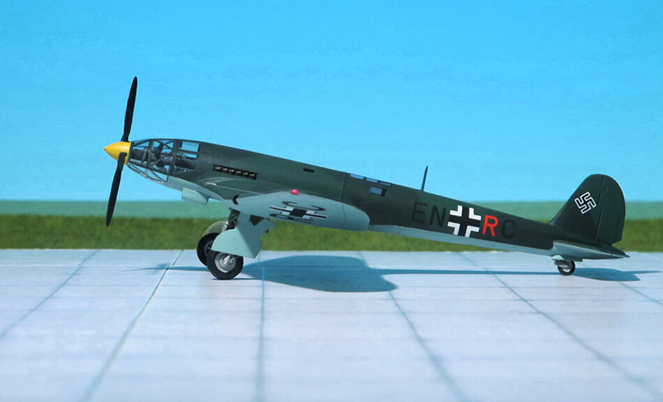
COMMENT: The Heinkel He 119 was an experimental single-propeller monoplane with two coupled engines, developed in Germany. A private venture by Heinkel to test radical ideas by the Günter brothers, the He 119 was originally intended to act as an unarmed reconnaissance bomber capable of eluding all fighters due to its high performance.
Design was begun in the late summer of 1936. A notable feature of the aircraft was the streamlined fuselage, most likely as an evolutionary descendant of the 1932-vintage Heinkel H 70 record-setting single-engined mailplane design, but without the He 70’s protruding canopy-enclosed crew accommodation existing anywhere along the exterior. Instead, the He 119’s forward fuselage featured an extensively glazed cockpit forming the nose itself, heavily framed with many diagonally braced windows immediately behind the propeller spinner’s rear edge. Two of the three-man crew sat on either side of the driveshaft, which ran aft to a “power system”, a coupled pair of Daimler-Benz DB 601 engines mounted above the wing center-section within the fuselage, mounted together within a common mount (the starboard component engine having a “mirror-image” centrifugal supercharger) with a common gear reduction unit fitted to the front ends of each component engine, forming a drive unit known as the Daimler-Benz DB 606, the first German aircraft to use the “high-power” power plant system meant to provide German aircraft with an aviation power plant design of over 2,000 PS output capability.
The DB 606 engine was installed just behind the aft cockpit wall, near the center of gravity, with an enclosed extension shaft passing through the centerline of the extensively glazed cockpit to drive a large four-blade variable-pitch airscrew in the nose. An evaporative cooling system was used on the first aircraft (V1), with the remaining prototypes receiving a semi-retractable radiator directly below the engine to augment cooling during take-off and climb.
Only eight prototypes were completed and the aircraft did not see production, mainly because of the shortages of DB 601 “component” engines to construct the 1,500 kg “power systems” they formed. The first two prototypes were built as land planes, with retractable landing gear. The third prototype (V3) was constructed as a seaplane with twin floats. This was tested at the “Erprobungsstelle Travemünde” military seaplane test facility on the Baltic coast, and was scrapped in 1942 at Heinkel’s factory airfield in the coastal Rostock-Schmarl community, then known as Marienehe.
On November 1937, the fourth prototype (V4) made a world class-record flight in which it recorded an airspeed of 314 mph, with a payload of 1,000 kg, over a distance of 1,000 km. The four remaining prototypes were completed during the spring and early summer of 1938, the V5 and V6 being A-series production prototypes for the reconnaissance model, and the V7 and V8 being B-series production prototypes for the bomber model.
These four aircraft were three-seaters with a defensive armament of one 7.92 mm MG 15 machine gun in a dorsal position, V7 and V8 having provision for a normal bombload of three 250 kg bombs or maximum bombload of 1,000 kg. V7 and V8 were sold to Japan in May 1940, and extensively studied; the insights thus gained were used in the design of the Yokosuka R2Y1 “Keiun” The remaining prototypes served as engine test-beds, flying with various prototype versions of the DB 606 and DB 610 (twinned Daimler-Benz DB 605) and the experimental DB 613 (twinned Daimler-Benz DB 603).
In 1944, a high-speed bomber development, designed as a private venture by Heinkel to test radical ideas by the Günter brothers, was the Heinkel He 519. It was designed to use the 24-cylinder Daimler-Benz DB 613, but the aircraft remained a concept and was abandoned at the end of the war. (Ref.: 24).
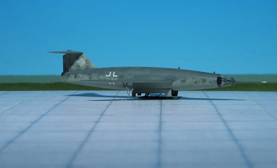
COMMENT: The DFS 346 was a German rocket-powered swept-wing aircraft subsequently completed and flown in the Soviet Union after WW II. It was designed by Felix Kracht at the Deutsche Forschungsanstalt für Segelflug (DFS, “German Research Institute for Sailplanes”). The prototype was still unfinished by the end of the war and was taken to the Soviet Union where it was rebuilt, tested and flown.
The DFS-346 was a midwing design of all-metal construction. The front fuselage of the DFS 346 was a body of rotation based on the NACA-Profile 0012-0,66-50. The middle part was approximately cylindrical and narrowed to the cut off to accommodate vertically arrayed nozzles in back. Probably for volume and weight reasons the DFS-346 was equipped with landing skids, both in the original German design and in the later Soviet prototypes; this caused trouble several times.
The wings had a 45° swept NACA 0012-0,55-1,25 profile of 12% thickness. The continuously varying profile shape caused a stall in certain flight conditions, which caused complete loss of control. This was later corrected by use of fences on the top of the wings.
The DFS 346 was a parallel project to the DFS 228 high-altitude reconnaissance aircraft, designed under the direction of Felix Kracht and his team at DFS. While the DFS 228 was essentially of conventional sailplane design, the DFS 346 had highly-swept wings and a highly streamlined fuselage that its designers hoped would enable it to break the sound barrier.
Like its stablemate, it also featured a self-contained escape module for the pilot, a feature originally designed for the DFS 54 prior to the war. The pilot was to fly the machine from a prone position, a feature decided from experience with the first DFS 228 prototype. This was mainly because of the smaller cross-sectional area and easier sealing of the pressurized cabin, but it was also known to help with g-force handling.
The DFS 346 design was intended to be air-launched from the back of a large mother ship aircraft for air launch, the carrier aircraft being the Dornier Do 217K as with the DFS 228. After launch, the pilot would fire the Walter HWK 109-509B/C twin-chamber engine to accelerate to a proposed speed of Mach 2.6 and altitude of 100,000 ft. This engine had two chambers — the main combustion chamber as used on the earlier HWK 509A motor; but capable of just over two short 2,000 kp of thrust at full power, and the lower-thrust “Marschofen”, (Cruise chamber = throttleable chamber of either 300 kp (B-version) or 400 kp (C-version) top thrust levels mounted beneath the main chamber. After reaching altitude, the speed could be maintained by short bursts of the lower “Marschofen” (cruise chamber).
In an operational use the plane would then glide over England for a photo-reconnaissance run, descending as it flew but still at a high speed. After the run was complete the engine would be briefly turned on again, to raise the altitude for a long low-speed glide back to a base in Germany or northern France.
Since the aircraft was to be of all-metal construction, the DFS lacked the facilities to build it and construction of the prototype was assigned to Siebel Werke located in Halle, where the first wind tunnel models and partially built prototype were captured by the advancing Red Army.
On 22 October 1946, the Soviet OKB-2 (Design Bureau 2), under the direction of Hans Rössing and Alexandr Bereznyak, was tasked with continuing its development. The captured DFS 346, now simply called “Samolyot 346” (“Samolyot” = Aircraft) to distance it from its German origins, was completed and tested in TsAGI wind tunnel T-101. Tests revealed some aerodynamic deficiencies which would result in unrecoverable stalls at certain angles of attack. This phenomenon involved a loss of longitudinal stability of the airframe. After the wind tunnel tests, two wing fences were installed on a more advanced, longer version of the DFS-346, the purpose of fences was to interrupt the spanwise movement of airflow that would otherwise bring the boundary-layer breakdown and transition from attached to stalled airflow with loss of lift and increase of drag.
This solution was used on the majority of the Soviet planes with sweptback wings of the 1950s and 1960s. In the meantime, the escape capsule system was tested from a North American B-25J “Mitchell” piston engine medium bomber and proved promising. Despite results from studies showing that the plane would not have been able to pass even Mach 1, it was ordered to proceed with construction and further testing.
In 1947, an entirely new 346 prototype was constructed, incorporating refinements suggested by the tests. This was designated “346-P” (“P” for planer = “glider”). No provision was made for a power plant, but ballast was added to simulate the weight of an engine and fuel. This was carried to altitude by a Boeing B-29 “Superfortress” captured in Vladivostok and successfully flown by Wolfgang Ziese in a series of tests. This led to the construction of three more prototypes, intended to lead to powered flight of the type.
Newly built “346-1“ incorporated minor aerodynamic refinements over the 346-P, and was first flown by Ziese on September 30, 1948, with dummy engines installed. The glider was released at an altitude of 9700 m, and the pilot realized that he hardly could maintain control of the aircraft. Consequently, while attempting to land, he descended too fast (his speed was later estimated at 310 km/h). After first touching the ground he bounced up to a height of 3–4 m and flew 700–800 m. At the second descent, the landing ski collapsed and the fuselage hit the ground hard.
The pilot seat structure and safety belt proved to be very unreliable, because at the end of a rough braking course Ziese was thrown forward and struck the canopy with his head, losing consciousness. Luckily, he wasn’t seriously injured, and after treatment in hospital he was able to return to flying. Accident investigation research team came to the conclusion that the crash was a result of pilot error, who failed to fully release the landing skid. This accident showed that the aircraft handling was still very unpredictable, as a result, all rocket-powered flights were postponed until pilots were able to effectively control the aircraft in unpowered descent, requiring further glide flights.
The damaged 346-1 was later repaired and modified to 346-2 version. It was successfully flown by test pilot P. Kazmin in 1950-1951 winter, but nonetheless these flights also ended “on fuselage”. Furthermore, after the last flight of these series, the airframe again required major repairs. On 10 May 1951, Ziese returned to the program, flying final unpowered test flights with the 346-2, and from 6 June, unpowered tests of the 346-3 without accidents.
By the mid-1951 346-3 was completed, and Ziese flew it under power for the first time on 13 August 1951, using only one of the engines. Continuing concerns about the aircraft’s stability at high speeds had led to a speed limit of Mach 0.9 being placed during test flights. Ziese flew it again on 2 September and 14 September. On this last flight, however, things went drastically wrong. Separating from the carrier plane at 9,300 meters (30,500 ft) above Lukovici airfield, the pilot fired the engine and accelerated to a speed of 900 km/h (560 mph). The rocket engine worked as expected, and 346-3, quickly accelerating, started ascending and soon had flown in very close proximity of its carrier aircraft. Ziese then reported that the plane was not responding to the controls, and was losing altitude. Ground control commanded him to bail out. He used the escape capsule to leave the stricken aircraft at 6,500 meters (21,000 ft) and landed safely by parachute. With the loss of this aircraft, the 346 program was abandoned (Ref.:24).
ACCOMMODATION: Pilot only in prone position in pressurized cockpit
POWER PLANT: One Walter HWK 109-509 bi-fuel liquid rocket engine, rated at 1,650 kp at 40,000 ft
PERFORMANCE: 435 mph at 75,459 ft
COMMENT: Beginning in 1940, the DFS (Deutsches Forschungsinstitut für Segelflug, German Research Institute for Sailplanes) started an ambitious program to achieve supersonic flight. Since the only engines powerful enough and available at the time were rocket engines, it was realized that the solution was to have the assault on the sound barrier take place at a high altitude. It was decided to divide the program into three sections:
The first part was concerned with developing and testing of the pressurized cockpit section, the method of pilot escape in case of emergency and performance testing of rocket engines at high altitudes.
The second part was to discover the performance of various sweptback wing configurations. The DFS acquired the Heinkel P.1068 designs for a four-engined turbojet bomber with various wing sweep angles.
The third and last part was to actually build a supersonic aircraft with information learned in the above two steps, which was eventually to become the DFS 346.
The DFS decided to design a new aircraft (although much was learned in an earlier design, the DFS 54) to investigate the first part of their three-step program. Thus, in 1941, the RLM assigned the number 228 to the aircraft, and requested that the DFS 228 also be designed for high-altitude reconnaissance duties as well as research work.
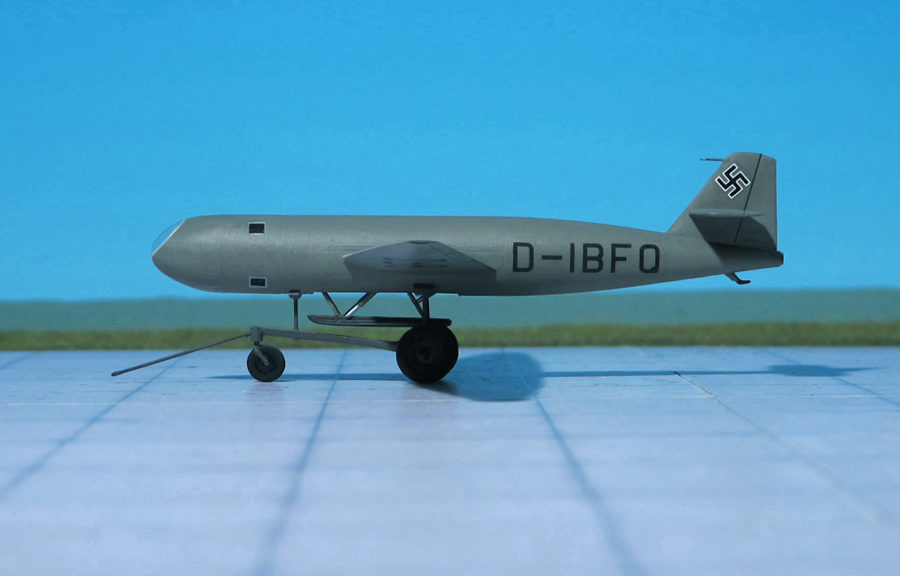
The first prototype of the DFS 228 (coded D-IBFQ) was completed in 1943 by the DFS, although the control sections and landing skid were built by Schmetz Company. The fuselage of the DFS 228 V1 consisted of three circular sections: the nose section containing the cockpit; a center section which contained the landing skid, fuel tanks and a Zeiss infra-red camera; and the tail section with the Walter HWK 509A-1 or A-2 rocket engine. The wing was attached at the mid-fuselage point, and featured 4.5 degrees of dihedral. Wooden construction was used for the entire wing, with a single laminated wooden spar running from wingtip to wingtip, wooden ribs and a plywood covering. Wide-span divided ailerons were fitted to the wing (the inner section acted as landing flaps), and lift spoilers were also fitted to the upper and lower wings. A conventional tail unit was used, also with all wooden construction. Landing was done on a retractable skid. Since the DFS 228 was to operate in extremely high altitudes, a completely pressurized cockpit was designed. Although it was thought at first that the pressure cabin could be of wooden construction, a metal compartment was built after the wooden one failed to hold sufficient pressure. The nose section was double-walled constructed with aluminum foil insulation. The V1 prototype had a conventional seated pilot’s position, but the V2 and later aircraft were to have a prone pilot position, due to the difficulty of of sealing such a large compartment with the pilot seated upright. All glazed areas were made of double layered Plexiglas and were provided with warm air circulation between layers to prevent frosting of the Plexiglas.
After pressure sealing problems became apparent on the V1 cockpit, it was decided to go with a prone pilot. An adjustable horizontal couch was provided for the pilot to lay on; all controls, oxygen supplies and cockpit equipment mounted directly to the steel tube structure which was then attached directly to the main fuselage bulkhead at the back of the cockpit. This also had the added advantage of keeping the pressurized area small. Thus it was easier to keep sealed. The new cockpit arrangement was incorporated in to the DFS 228 V2 and later aircraft.
A very interesting flight plan was arranged for the operational recognizance DFS 228. It was to be mounted above (or could be towed behind) a carrier aircraft (usually a Do 217K), where it was then carried to approximately 32.808 feet. Upon release, the DFS 228 would then ignite its rocket engine until an altitude of about 75.460-82.021 feet was reached. By this time, the DFS 228 would be over its photographic target area and after its reconnaissance mission was fulfilled, the aircraft would then make a long glide back to base.
In the case of an emergency at high altitudes, the complete pressurized nose section (with all life support equipment attached) could be jettisoned by firing four explosive bolts, or it could take place automatically when the cockpit pressure dropped below a minimum level. An automatic parachute would then deploy to stabilize and slow the descent. When a safe altitude was reached, the pilot was ejected by compressed air, and would then descend to the ground using his personal parachute. This escape procedure was successfully tested by the Soviets after the war, with a captured DFS 346, which had a similar escape system.
DFS 228 V1 flight trials were made at Hörsching, southwest of Linz, by the DFS and also by Erprobungsstelle Rechlin in late 1944. Over 40 test flights were made, and although powered flight was to take place in February 1945, none were actually made using rocket power, and none exceeded 32.808 feet. It was in these tests that the upright pilot’s position was found to be unsuitable for proper cockpit pressurization. The decision was made to go with the prone position cockpit, and was included into the DFS 228 V2, which was built and also flight tested.
The main faults found with the 228 were that it suffered from poor aileron effectiveness at high altitudes and that the elevators were very sensitive. Other than the early pressurization problems, the general handling was satisfactory and the problems would not hamper the intended role of the aircraft. A potential problem could have arisen with the use of the Walter HWK 509A1 or A-2 rocket engines, due to the fact that the flight profile meant for the rocket engine to be intermittently operated, and the possibility existed of valves and pumps freezing up at the extreme altitudes and low temperatures in which the flight was to take place. Of course, newer rocket engines were continually being developed, and perhaps some sort of heating system or the possibility of using M-Stoff and A-Stoff (methanol and oxygen) for fuels, which could have operated at much lower temperatures, could have been developed.
Although powered flight had not been attempted at the time of Germany’s collapse, the construction of a pre-production batch of 10 DFS 228A-0 aircraft had begun at Griesheim, near Darmstadt.
The DFS 228 V2 was destroyed at Hörsching in May 1945, only the forward section had parts worth salvaging. The DFS 228 V1 survived the war, and was surrendered at Ainring in the US Zone of Occupation. On June 18, 1945, it was taken by road to the US Air Technical Intelligence Unit at Stuttgart. It was later sent to the RAE Farnborough in June 1946, and although allegedly was sent to the scrap pile in 1947, another report has the DFS 229 V1 being sent to Slingsby Sailplanes Ltd. at Kirkbymoorside in Yorkshire. Strangely enough, Slingsby offered a design for their T44, a stratospheric research sailplane which incorporated several DFS 228 features, including the detachable pressurized cockpit section (Ref.: 17).
POWER PLANT: One Argus As 10c air-cooled inline piston engine, rated at 240 hp
PERFORMANCE: 103 mph
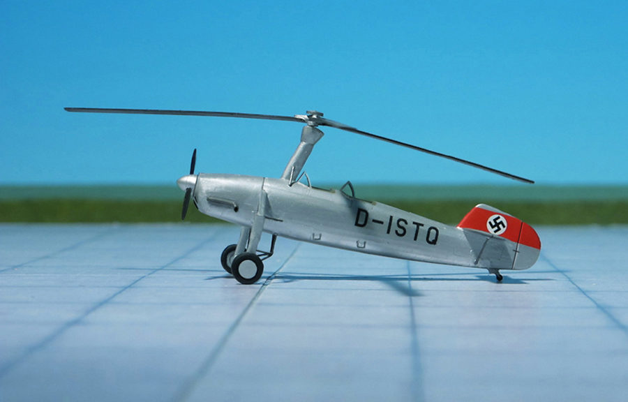
COMMENT: German helicopter development began with Focke-Wulf’s acquisition of the rights to manufacture Cierva autogyros during the 1920’s. Over 30 Cierva C.19 and C.30 autogyros were built during the late 1920’s and early 1930’s, and from this experience, Heinrich Focke, the engineering half of the Focke-Wulf company, decided to develop an original autogyro design to compete in the Luftwaffe’s contest to provide a utility-liaison aircraft. The Focke-Wulf entry, designated Fw 186, was essentially a Focke-Wulf Fw 56 “Stösser” (Goshawk) parasol wing advanced trainer, with wings removed, tail unit and landing gear redesigned, and configured for two seats in tandem. The engine remained unchanged, with a clutch arrangement installed to start the blades rotating for takeoff. An autogyro, similar in principle to today’s gyrocopters, uses the main power plant for forward thrust, while the rotors freewheel in flight. The aircraft could take off and land in very short distances, but it could not hover or take off and land vertically.
The first flight of the Focke-Wulf Fw 186 was on July 1939 and although very successful, it was beaten out by the Fieseler Fi 156 “Storch” (Stork) for the Luftwaffe contract, and disappeared from the scene afterward. Only two examples were built (Ref.: Planet Models).
POWER PLANT: Two Daimler-Benz DB 603B liquid-cooled engines, rated at 1,860 hp at 6,900 ft each and one Daimler-Benz DB, rated at 1,475 hp driving “HZ-Anlange” supercharger in fuselage
PERFORMANCE: 379 mph at 45,900 ft
COMMENT: The Henschel Hs 130 was a high-altitude reconnaissance aircraft and bomber developed in WW II, but never used operationally, only existing as prototype airframes due to various mechanical faults.
Development of the Hs 130 began with two Hs 128 prototypes, which first flew on 11 April 1939, with the second prototype flying on 20 February 1940. Both prototypes were research aircraft, used for testing pressurized cabins, engine superchargers, and cantilever wings. Different engines powered the two prototypes; the V1 by Daimler-Benz DB 601s and the V2 by Junkers Jumo 201s. Both had fixed landing gear.
While trials of the two prototypes were not successful, the potential of a high altitude aircraft caught the attention of the commander of the Luftwaffe’s’s special reconnaissance unit. The interest in the Hs 128’s potential for high-altitude reconnaissance missions led the RLM (Reich Air Ministry) to instruct Henschel to continue development of the Hs 128 as a reconnaissance aircraft under the designation Hs 130A. Three prototype aircraft Hs 130As were built, the first flying on May 1940. Five pre-production Hs 130A-0 followed, being delivered in early 1941, and featured Daimler-Benz DB 601R engines – each with a single-stage supercharger, retractable landing gear, and a bay in the rear to house two Rb75/30 cameras for reconnaissance. The five Hs 130A-0s subsequently underwent trials and testing, which revealed significant problems with the aircraft performance, and reliability problems which prevented operational use.
Two further modified Hs 130A-0s were produced under the designation Hs 130A-0/U6 and featured a greater wingspan, Daimler-Benz DB 605B engines, Hirth superchargers, GM-1 nitrous oxide power boosting, and under-wing drop tanks, and being ready for flight testing in November 1943, demonstrating an absolute ceiling of 50,570 ft. The Hs 130A-0/U6 variant as well as the other Hs 130A-0s proved unsatisfactory and were never flown operationally.
Further development of the Hs 130 led to bomber variants. The planned Hs 130B was almost the same as the Hs 130A, but with a bomb bay in place of the camera bay, but was never built. The Hs 130C was built as a competitor for the “Bomber B” project, and was very different from the Hs 130A, featuring a shorter wing span, remotely controlled defensive armament, a more extensively glazed but still pressurized cabin and up to 4,000 kg of bombs. Further development of the Hs 130 as a reconnaissance aircraft continued with the Hs 130D, which was planned to have DB 605 engines and a complex two-stage supercharger, but was again unbuilt.
The Hs 130E was a re-working of the Hs 130A with the “Höhen Zentrale” or “HZ-Anlage” (High-altitude gear center) in place of conventional superchargers. The “HZ-Anlage” operated by a third engine, a Daimler-Benz DB 605T, was installed in the fuselage the only purpose of which was to power a large supercharger to supply air to the wing-mounted DB 603B engines. Another difference from the Hs 130A was the nose, which was extended forward to offset the weight of the “HZ-Anlage” engine in the fuselage. Also underwing fuel tanks could be fitted to provide fuel for three engines, and air scoops were fitted under the fuselage to supply the fuselage engine.
Three prototype Henschel Hs 130Es were built; Hs 130E V1 first flew in September 1942, and could reach 41,010 ft when “HZ-Anlage” was employed. Hs 130E V2, first flown in November 1942, was lost on its seventh flight due to an engine fire; V3 was built to replace it. An order for seven pre-production Hs 130E-0s followed, first flying in May 1943, together with a production order was placed for 100 Hs 130E-1s which were to have a remotely controlled defensive armament and provisions for underwing bombs. The order was cancelled due to continuing problems suffered by the Hs 130E-0’s “HZ-Anlage” system. A four engine version Hs 130F was planned, which was hoped to solve the problems with “HZ-Anlage”, by using four supercharged BMW 801 radial engines, but was never built (Ref.: 24).
POWER PLANT: One Walter HWK 509C liquid-fuel rocket engine, rated at 2,400 kp thrust (main chamber: 2,000 kp thrust, auxiliary chamber 400 kp thrust)
PERFORMANCE: 569 mph (estimated)
COMMENT: In 1944 the Arado design team proposed a two liquid-rocket engines powered reconnaissance versions of the Arado Ar 234 “Blitz” (Lightning) high-speed bomber. The Arado Ar 234R, as it was designated, would consist of a regular Arado Ar 234C frame but without turbojet engines. Instead two pods were installed under the wing, each containing a Walter HWK 109-509A bi-fuel rocket engine (project Ar 234R-1A). The second project Ar 234R-1B was to be powered by a Walter HWK 109-509C two chamber liquid-fuel rocket engine mounted in the rear section. Therefore a cowling would have been installed in the rear fuselage underneath the rudder. The upper rocket engine called “Steigofen” (Accelerate chamber) delivered 2,000 kp and was to be used for climbing to altitude while the lower rocket engine, “Marschofen” (Cruising chamber) delivered 400 kp thrust and was used to power the aircraft during horizontal flight. During return flight – over a distance of more than 155 miles – the aircraft flew as a glider without power. The wing had a laminar profile with its maximal thickness at 50 to 60% chord. The glide ratio was calculated to 1:14.
Because of the limited fuel capacity and short endurance of the rocket engines the Ar 234R-1b was to be towed by a Heinkel He 177 “Greif” heavy bomber. A possible reconnaissance mission in the London area was calculated as follows: After take-off from a Luftwaffe base near Paris the aircraft was towed to the operational altitude of app. 26,247 ft, reached near Calais. After release of towline with “Steigofen” at full throttle the aircraft was powered at a speed of app. 506 mph to an altitude of app. 55,775 ft. This height was reached in a few minutes app. near the coast of Dover. During horizontal flight intermittent ignition of the “Marschofen” accelerated the aircraft with 569 mph to the target (i. e. London). After photo mission the aircraft flew back to the coast of England at a speed of 541mph and the descent back to the home base was flown as a glider. The mission was estimated for 21 minutes.
Although the Arado Ar 234R-1B project was promising it was abandoned in favor of the DFS 228 reconnaissance rocket-driven glider giving even better ceiling of 75,460 ft (Ref: 16).
Scale 1:72 aircraft models of World War II
Mit der weiteren Nutzung unserer Webseite erklären Sie sich damit einverstanden, dass wir Cookies verwenden um Ihnen die Nutzerfreundlichkeit dieser Webseite zu verbessern. Weitere Informationen zum Datenschutz finden Sie in unserer Datenschutzerklärung.