All posts by Gunther Arnold
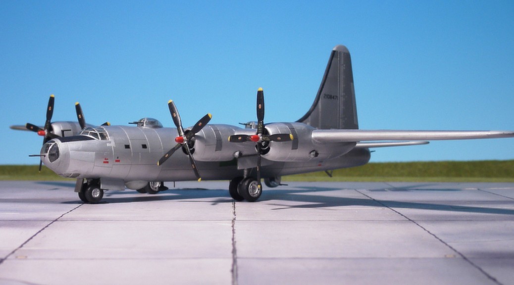
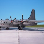
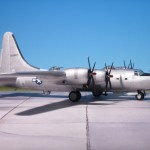
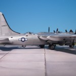
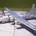
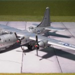
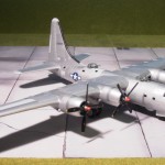
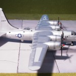
Consolidated B-32 “Dominator” (Anigrand, Resin)
TYPE: Heavy bomber
ACCOMMODATION: Crew of ten
POWER PLANT: Four Wright R-3350-23A radial engines, rated at 2,200 hp each
PERFORMANCE: 357 mph at 30,000 ft
COMMENT: The Consolidated B-32 “Dominator” was a heavy bomber made for the USAAF during WWII, and had the distinction of being the last Allied aircraft to be engaged in combat during World War II. It was developed in parallel with the Boeing B-29 “Superfortress” as a fallback design should the B-29 prove unsuccessful. The design on which Consolidated based its proposal was similar to the Consolidated B-24 “Liberator”. Like the B-24 it was originally designed with twin fins and a large Davis-type wing, but with a longer, rounder fuselage and a rounded nose. The aircraft was designed to be pressurized, and have remote-controlled retractable gun turrets with fourteen .50 in machine guns. The turrets were remotely controlled from periscopic sights in aiming stations inside the aircraft. The sights were coordinated by a sophisticated analog computer system. The inboard propellers’ pitch could be reversed to shorten the landing roll or to roll back in ground maneuvers. The first prototype made its maiden flight on 7 September 1942. In 1943, the initial contract was signed for 300 B-32 but development problems continued. In order to resolve stability problems a B-29 style tail was fitted to the aircraft after its 25th flight. But this did not resolve the problem and a Consolidated-designed 19.5 ft vertical tail was added and first flown on the third XB-32 on 3 November 1943. By 1944 testing of the three prototypes permitted the USAAF to place orders for over 1,500 B-32s. The first production aircraft was delivered on 19 September 1944, by which time the B-29 was in full combat in the Pacific Area of Action. Beginning on 27 January 1945, 40 B-32A-5, -10 and -15 aircraft were delivered as unarmed TB-32-CF crew trainers. The B-32 only reached units in the Pacific Area during mid-1945, and subsequently only saw limited combat operations against Japanese homeland before the end of the war. Most of the extant orders of the B-32 were cancelled shortly thereafter and only 118 B-32 airframes of all types were built (Ref.: 23).
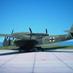
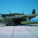
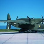
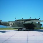
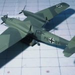
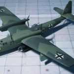
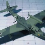
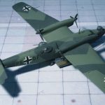
Dornier Do 26D-0 (Airmodel, Vacu)
TYPE: Transport and reconnaissance flying boat
ACCOMMODATION: Crew of four
POWER PLANT: Four Junkers Jumo 205D liquid-cooled, opposed-piston diesel engine, rated at 880 hp each
PERFORMANCE: 208 mph
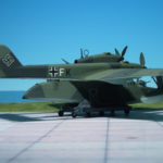
COMMENT: The elegant Dornier Do 26, sometimes referred to as the “most beautiful flying-boat ever built”, was of all-metal construction. Originally designed as a civilian transport aircraft for the “Deutsche Lufthansa”, the few aircraft built before and immediately at the beginning of WW II were pressed into military service at the outbreak of the war in Europe.
The hull had a central keel and a defined step; the wings were of gull wing configuration, the outer sections being equipped with fully retractable narrow stabilizing wing-floats, instead of Dornier’s famous “water-wing” sponsons extending from the lower hull for lateral stabilization.
Its four Junkers Jumo 205 diesel engine, were mounted in tractor/pusher pairs in tandem nacelles located at the joint between the dihedral and horizontal wing sections. The rear (pusher) engines could be swung upwards through 10° during take-off and landing, to prevent contact between the three-blade airscrew and water spray created by the forward propellers. The tail unit was of conventional design, comprising a horizontal tail-plane and a single, vertical fin with rudder. Armament consisted of one 20 mm MG 151/20 cannon in a power-operated bow turret and three 7.92 mm MG 15 machine guns.
Only six aircraft were built and put into Luftwaffe service. They were used in the Norwegian campaign for transporting supplies, troops and wounded to and from the isolated German forces fighting at Narvik. During this campaign three of them were lost. Another Dornier Do 24C was lost on 16 November 1940, killing its crew, after being launched at night from the catapult ship “Friesenland” in Brest, France. The fate of two remaining aircraft, which in 1944 were still assigned to the “Erprobungsstelle” (Test Unit) in Travemünde, Germany, is unclear (Ref.: 24).
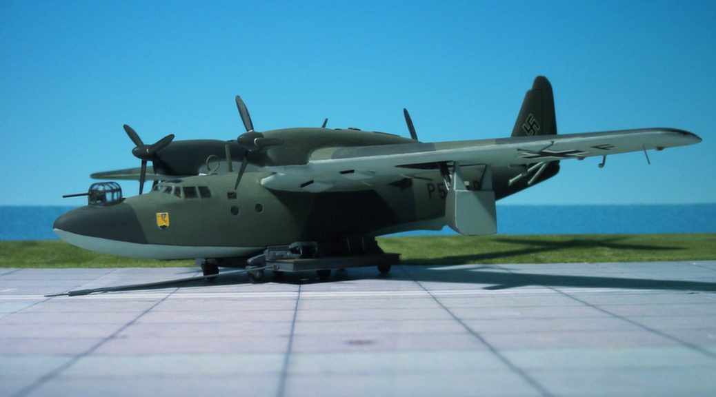
Blohm & Voss Bv 138C-1 (“Seedrache”, „Sea Dragon“), Supermodel
TYPE: Long-range maritime reconnaissance flying boat
ACCOMMODATION: Crew of six
POWER PLANT: Three Junkers Jumo 205D liquid-cooled, vertically opposed diesel engine, rated at 870 hp each
PERFORMANCE: 177 mph at 19,700 ft
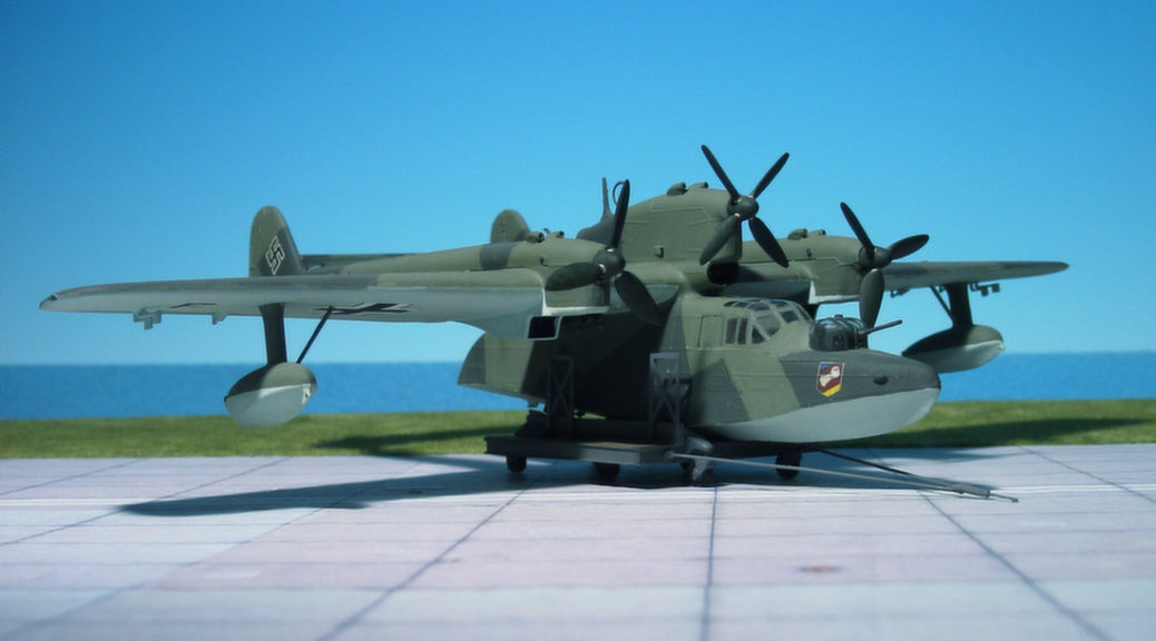
COMMENT: Originally developed under the company name of Hamburger Flugzeugbau, the type was initially designated the Ha 138. Its appearance was unique in its combination of unusual design features with its twin boom tail unit, short fuselage and trimotor engine configuration. The short hull, with its hydrodynamic step beneath and flat sides, earned it the nickname “Der fliegende Holzschuh” (“The flying clog”).
Three piston engines were used. The central engine was mounted above the wing, driving a four-blade propeller, while the wing engines were lower, with three-blade propellers. The pre-production prototypes were powered by various makes of engines ranging from 650–1,000 hp. The first standardized version, BV 138B-1, was powered by three 868 hp Junkers Jumo 250D two-stroke, opposed-piston aircraft diesel engines. The engine cowlings also had an atypical appearance, due to the unique nature of the vertical orientation of the six-cylinder opposed-piston Jumo 205 diesel engines, and resembled the cowlings of 4 or 6-cylinder inverted inline engines found on smaller civil and utility aircraft from the Jumo 205’s propshaft placement, emerging forward at the uppermost front end of the power plant.
The booms of the twin tail unit, much like the smaller Focke-Wulf Fw 189 twin-engine reconnaissance monoplane, extended horizontally from the rear of the outer engine nacelles.
For hydrodynamic reasons, the hull featured a distinct “turn-down”, or “beak” at the stern. Two enclosed, powered gun turrets, each mounting a single MG 151/20 autocannon, were located prominently at the bow and stern. A third, fully open Scarf ring-like emplacement, behind the central engine and both above and forward of the rear turret, mounted a MG 131 heavy machine gun covered fields of fire obstructed from the other turrets by the horizontal stabilizer.
In all, 227 examples of standard service variants of the BV 138 were built. The first such variant, Bv 138C-1, began service in March 1941. While non-standard variants carried a variety of armament, the standard variant featured two 20 mm MG 151/20 cannons, one in a power-operated bow turret and one in a power-operated stern turret, up to three 7.92 mm MG 15 machine guns, and a 13 mm MG 131 machine gun in the aft center engine nacelle. It could carry up to 500 kg of bombs or depth charges (under the starboard wing root only) or, in place of these, up to 10 passengers. Both the B-1/U1 and C-1/U1 variants had racks under both wings to double the offensive load.
Some examples of the BV 138 were adapted to specialized roles. The Bv 138 was tested with the oft-used Walter HWK 109-500 “Starthilfe” (RATO) jettisonable rocket pod, used in pairs, for shorter take-off performance. One anti-shipping variant carried FuG 200 “Hohentwiel” low-UHF band maritime search radar. The BV 138 MS variant was converted for minesweeping (suffix “MS” means “Minen-Suchgerät”, “mine-search” aircraft, and carried magnetic field-generating degaussing equipment, including a hoop antenna with a diameter equal to the length of the fuselage, which encircled the hull and wings, which was also used on certain models of the Junkers Ju 52/3m trimotor transport used for the same duty (Ref. 24).
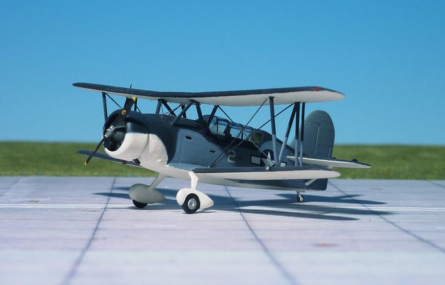
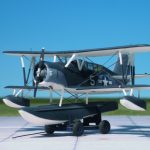
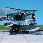
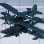
Curtiss SOC-2 “Seagull” (Hasegawa)
TYPE: Scout observation airplane, trainer
ACCOMMODATION: Pilot and observer
POWER PLANT: One Pratt & Whitney R-1340-18 radial engine, rated at 550 hp
PERFORMANCE: 165 mph at 5,000 ft
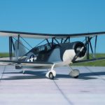
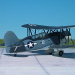
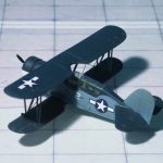
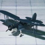
COMMENT: The Curtiss SOC “Seagull” was an American single-engine scout observation biplane aircraft, designed by the Curtiss-Wright Corporation for the US Navy. The aircraft served on battleships and cruisers in a seaplane configuration, being launched by catapult and recovered from a sea landing. The wings folded back against the fuselage for storage aboard ship. When delivered from factory or based ashore or on carriers the single float was replaced by fixed wheeled landing gear.
The SOC was ordered for production by the US Navy in 1933 and first entered service in 1935. The first order was for 135 SOC-1 models, which was followed by 40 SOC-2 models for landing operations and 83 SOC-3s. A variant of the SOC-3 was built by the Naval Aircraft Factory and was known as the SON-1
The SOC was not called the “Seagull” until 1941, when the U.S. Navy began the wholesale adoption of popular names for aircraft in addition to their alpha-numeric designations (Ref.:24).
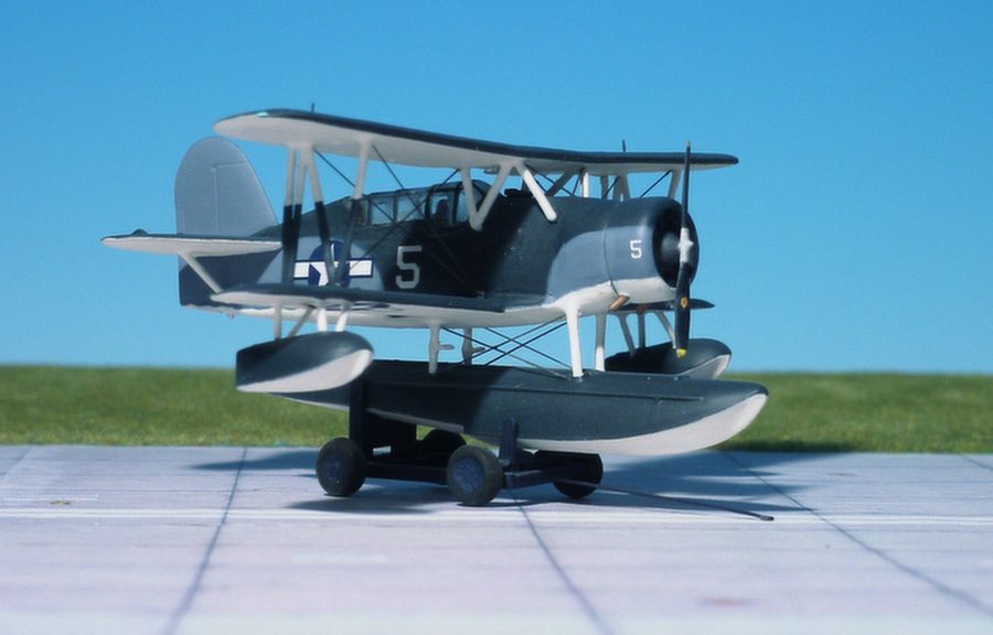
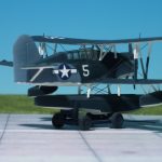
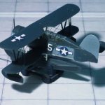
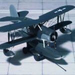
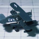
Curtiss SOC-3 “Seagull” (Hasegawa)
TYPE: Scout observation float-plane, trainer
ACCOMMODATION: Pilot and observer
POWER PLANT: One Pratt & Whitney R-1340-18 radial engine, rated at 550 hp
PERFORMANCE: 165 mph at 5,000 ft
COMMENT: The Curtiss SOC “Seagull” was an American single-engine scout observation biplane aircraft, designed by the Curtiss-Wright Corporation for the US Navy. The aircraft served on battleships and cruisers in a seaplane configuration, being launched by catapult and recovered from a sea landing. The wings folded back against the fuselage for storage aboard ship. When based ashore or on carriers the single float was replaced by fixed wheeled landing gear.
The SOC was ordered for production by the US Navy in 1933 and first entered service in 1935. The first order was for 135 SOC-1 models, which was followed by 40 SOC-2 models for landing operations and 83 SOC-3s. A variant of the SOC-3 was built by the Naval Aircraft Factory and was known as the SON-1
By 1941, most battleships had transitioned to the Vought OS2U “Kingfisher” and cruisers were expected to replace their aging SOCs with the third generation Curtiss SO3C “Seamew”. The SO3C, however, suffered from a weak engine and plans to adopt it as a replacement were scrapped. The SOC, despite belonging to an earlier generation, went on to execute its missions of gunfire observation and limited range scouting missions.
The SOC was not called the “Seagull” until 1941, when the U.S. Navy began the wholesale adoption of popular names for aircraft in addition to their alpha-numeric designations.
When operating as a seaplane, returning SOCs would land on the relatively smooth ocean surface created on the sheltered side of the vessel as it made a wide turn, after which the aircraft would be winched back onto the deck.
When the SOC was replaced by the OS2U “Kingfisher”, most remaining airframes were converted into trainers; they remained in use until 1945. With the failure of the Curtiss SO3C “Seamew”, many SOCs in second line service were returned to frontline units starting in late 1943. They saw service aboard warships in the combat zone for the rest of World War II. This is one of the few instances in aviation history in which an older aircraft type, that was retired or sent to second line service, replaced the new aircraft type that was intended to replace it (Ref.: 24).
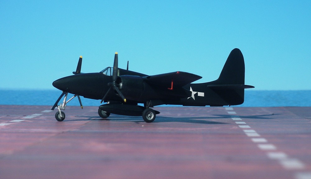
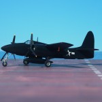
Grumman F7F-1 Tigercat (Monogram)
TYPE: Carrier-based fighter-bomber
ACCOMMODATION: Pilot only
POWER PLANT: Two Pratt & Whitney R-2800-22W Double Wasp engines, rated at 2,100 hp each
PERFORMANCE: 427 mph at 19,200 ft
COMMENT: In mid 1938, the US Navy had ordered a prototype twin-engine fighter from the Grumman Company and, by middle of 1941, preliminary flight-test data for this aircraft, the XF5F-1 (Grumman G-45) was available. Although the XF5F-1 suffered a number of shortcomings, it provided a useful basis for the development of a larger twin-engine fighter. Ordered in June 1941 and designated XF7F-1 this new fighter was intended to be operated from the forthcoming 45,000 ton carriers of the USS Midway class. It was the Navy’s first twin built in production quantities, and the first carrier-based fighter to operate with a tricycle undercarriage. Although classified as a fighter the aircraft was designed to operate in a ground-support role, for which it was heavily armed. In early 1944 an order for 500 Tigercats was given and deliveries began in April 1944. Operational problems and changing requirement let to restriction in the production program. After 34 F7F-1 had been delivered production switched to 189 F7F-3s, similar to the single-seat model but with more powerful R-2800-34W engines. Including two-seated night-fighter variants , the Grumman F7F-3N Tigercat, production totaled 250 aircraft. Too late for operational service in WW II, the Tigercat served with a few Marine squadrons after the war but was soon displaced by the advent of jet-powered aircraft. (Ref. 18)
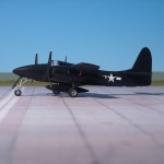
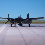
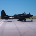
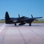
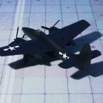
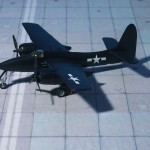
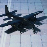
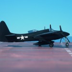
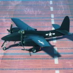
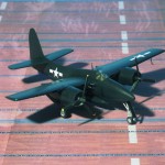
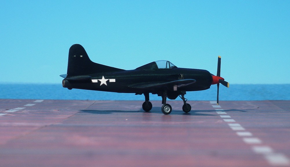
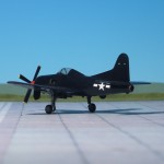
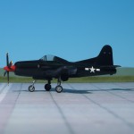
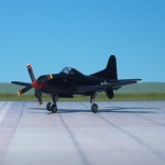
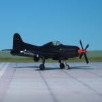
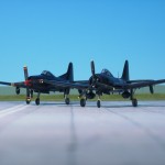
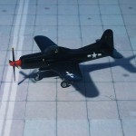
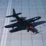
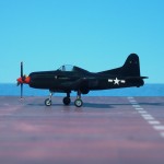
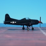
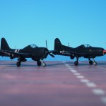
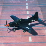
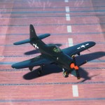
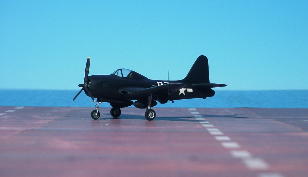
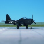
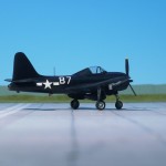
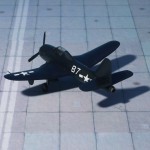
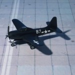
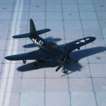
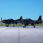
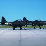
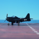
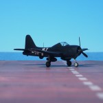
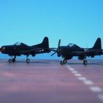
Ryan F2R-1 Dark Shark (MPM)
TYPE: Carrier-borne fighter
ACCOMMODATION: Pilot only
POWER PLANT: General Electric XT31-GE-2 turboprop and General Electric J31-GE-3 turbojet
PERFORMANE: 497 mph at sea level
COMMENT: The Ryan XF2R Dark Shark was an American experimental aircraft built for the United States Navy that combined turboprop andturbojet propulsion. It was based on Ryan Aeronautical’s earlier FR Fireball, but replaced the Fireball’s piston engine with a turboprop engine.
The XF2R Dark Shark was based on Ryan Aeronauticl’s earlier FR Fireball, but replaced the Fireball’s piston engine with a General Electric T31 turboprop engine driving a 4-bladed Hamilton Standard propeller. The turboprop made for much improved performance over the Fireball, but the Navy showed little interest in it; by that time, they had abandoned the idea of the combination fighter and were instead looking into all-jet fighters.
The United States Air Force, however, showed a little more interest; they were at the time evaluating the Convair XP-81 of similar concept, and asked Ryan to modify the XF2R to use the Westinghouse J34 turbojet instead of the General Electric J31 used previously. Modifications to theprototype created the XF2R-2, with the jet intakes moved to the sides of the forward fuselage with NACA ducts instead of the inlets in the wing leading edge used before.
Although the Dark Shark proved to be a capable aircraft, it never got further than the prototype stage; all-jet aircraft were considered superior (Ref.: 24).
Ryan FR-1 Fireball (Airmodel, Vacu)
TYPE: Carrier-borne fighter
ACCOMMODATION: Pilot only
POWER PLANT: One Wright R-1820-72W Cyclone 9 air-cooled radial engine, rated at 1,350 hp and General Electric J31-GE-3 turbojet, engine rated at 700 kg thrust
PERFORMANCE: 404 mph at 17,800 ft
COMMENT: The Ryan FR- Fireball was a mixed-power fighter aircraft designed by Ryan Aeronautical for the US Navy during WW II. It was the Navy’s first aircraft with a turbojet engine. Only 66 aircraft were built before Japan surrendered in August 1945. The FR-1 Fireball equipped a single squadron before the war’s end, but did not see combat. The aircraft ultimately proved to lack the structural strength required for operations aboard aircraft carriers and was withdrawn in mid-1947.
Design of the FR-1 began in 1943 for a mixed-powered fighter because early turbojet engines had sluggish acceleration that was considered unsafe and unsuitable for carrier operations. Ryan received a contract for three XFR-1 prototypes and one static test airframe on February 1943 with the first two prototypes delivered in 14 months. Another contract was placed for 100 aircraft on December 1943 and a later contract on January 1945 increased the total of FR-1s on order to 700.
The XFR-1 was a single-seat, low-wing monoplane with tricycle landing gear. A 1,350 hp Wright R-1820-72W Cyclone radial engine was mounted in the fighter’s nose while a 724 kp thrust delivering General Electric I-16 (later redesignated as the J-31) turbojet was mounted in the rear fuselage. It was fed by ducts in each wing root which meant that the wing had to be relatively thick to house the ducts and the outward-retracting main landing gear. To simplify the fuel system, both engines used the same grade of avgas. Two self-sealing fuel tanks were housed in the fuselage. The cockpit was positioned just forward of the leading edge of the wing and the pilot was provided with a bubble canopy which gave him excellent visibility. The XFR-1 had the first laminar flow airfoil in a navy carrier aircraft.
The Fireball was armed with four 12.7 mm M2 Browning machine guns. They were mounted in the center section of the wing, immediately outboard of the air intakes for the jet engine. Four 127 mm rockets could be carried under each outer wing panel and two hardpoints were provided under the center section for 454 kg bombs or drop tanks. Armor plates were provided in front and behind the pilot’s seat and for the oil cooler
The first XFR-1 made its first flight on June 1944 without ist turbojet engine, but this was installed shortly afterward. The second prototype first flew on September 1944. Test flights confirmed wind tunnel tests that revealed a lack of longitudinal stability because the center of gravity had been miscalculated. In addition, the circular rear fuselage of the FR-1 gave less stability than the slab-style fuselage of the Grumman F4F Wildcat that was used as a model for the stability calculations. A new tail with enlarged vertical andhorizontal stabilizers was designed and retrofitted to the prototypes.
The first prototype was lost in a crash on October 1944. Investigation showed that the wing structure was not strong enough to resist compressibility effects. This was cured by doubling the number of rivets in the outer wing panels. The second prototype crashed on March 1945 when the pilot failed to recover from a dive from 35,000 feet, probably also due to compressibility effects. The third prototype crashed on April when the canopy blew off during a high-speed pass.
Operational testing by the Naval Air Test Center (NATC) at Naval Air Station Patuxent River that included carrier acceptability tests revealed additional problems: The piston engine tended to overheat until electrically operated cowl flaps were installed, the catapult hooks had to be moved, and the nosewheel oleo shock strut had to be lengthened. Carrier suitability tests began aboard the escort carrier CVE 30 Charger in early January 1945. The aircraft successfully made five catapult take-offs using the piston engine as well as three take-offs using both engines. No problems were reported when landing aboard the carrier.
On December 1943, orders for 100 production FR-1s were placed, with a follow-up order of 1,000 additional fighters in January 1945. All of the contracts were contingent on the aircraft successfully completing carrier trials. Only 66 Ryan FR-1 Fireballs were completed by November 1945 as orders for 1,044 FR-1s were canceled on VJ Day.
One squadron, VF-66, received its first Fireballs in March 1945, but they never saw combat. On 1 May, three of the squadron’s aircraft were craned aboard the carrier CV-4 Ranger to attempt to qualify seven pilots, but two of the fighters were damaged while landing. One missed the arresting gear and hit the crash barrier while the other aircraft’s nose gear collapsed. The following month the pilots qualified and were on pre-embarcation leave when the Japanese surrendered. The squadron was decommissioned on 18 October 1945 with all pilots and aircraft transferred to VF-41. On 6 November 1945, a Fireball of VF-41 became the first aircraft to land under jet power on an aircraft carrier, albeit without prior planning. After the radial engine of an FR-1 failed on final approach to the escort carrier CVE-65 Wake Island, the pilot managed to start the jet engine and land, barely catching the last arrestor wire before hitting the ship’s crash barrier (Ref.: 24).
Messerschmitt Me 108B Taifun (Fly)
TYPE: Personal transport and liaison aircraft
ACCOMMODATION: Crew of one or two
POWER PLANT: One Argus As 10E air-cooled inline engine, rated at 266 hp
PERFORMANCE: 190 mph
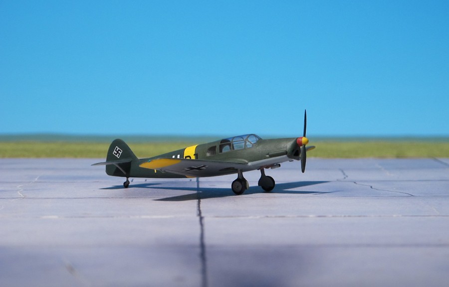
COMMENT: The Messerschmitt Bf 108 Taifun (“Typhoon”) was a German single-engine sport and touring aircraft, developed by Bayrische Flugzeugwerke in the 1930s. The Bf 108 was of all-metal construction.Originally designated the M 37, the aircraft was designed as a four-seat sports/recreation aircraft for competition in the 4th Challenge International de Tourisme (1934). The M 37 prototype flew first in spring 1934, powered by a 247 hp Hirth HM 8U air-cooled engine, which drove a three-blade propeller.
Although it was outperformed by several other aircraft in the competition, the M 37’s overall performance marked it as a popular choice for record flights. Particular among these traits was its low fuel consumption rate, good handling, and superb takeoff and landing characteristics.
The Bf 108A first flew in 1934, followed by the Bf 108B in 1935. This revised version, built from late 1935. The prototype had a Siemens-Halske Sh 14A radial, but production machines used the the substantially larger, 12.67 litre displacement 237 hp Argus As 10C or the 266 hp Argus As 10E air-cooled inverted V8 engine.. A quadrant-shaped rather than rectangular rear window, tailwheel replacing skid, revision of shape of empennnage and removal of tailplane upper bracing was introduced.The Bf 108B used The nickname Taifun (“typhoon”) was given to her own aircraft by Elly Beinhorn, a well-known German pilot, and was generally adopted.
Soon after the first production aircraft began to roll off the assembly line in Augsburg, several Bf 108s had set endurance records.
The Bf 108 was adopted into Luftwaffe service during World War II, where it was primarily used as a personal transport and liaison aicraft.
Production of the Bf 108 was transferred to occupied France during World War II and production continued after the war as the Nord 1000 Pingouin. In total 885 aircraft have been built (Ref.: 24).
