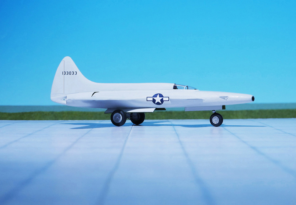
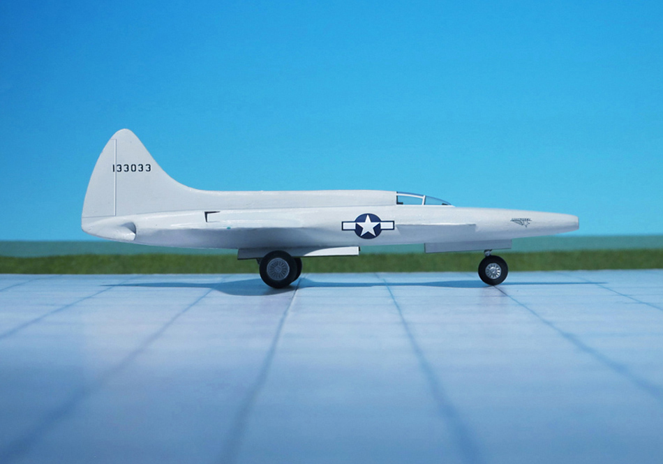
POWER PLANT: Two Lockheed L-1000 axial-flow turbojets 2,345 kp thrust each
PERFORMANCE: 625 mph
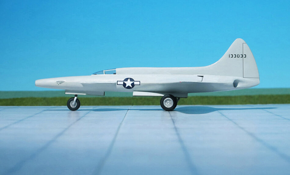
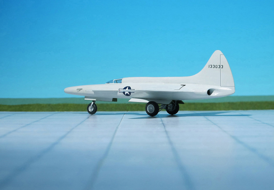
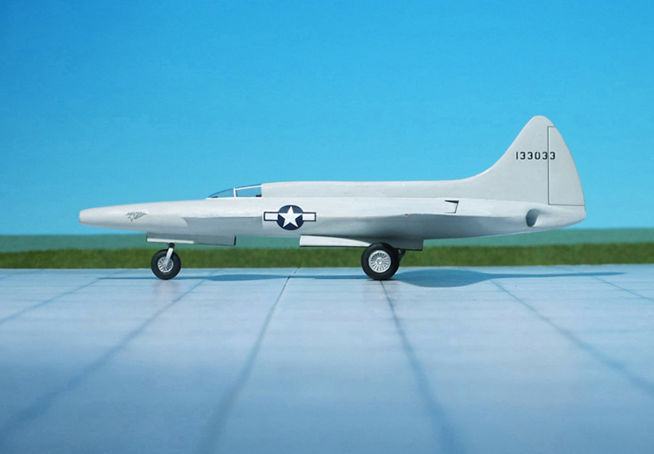
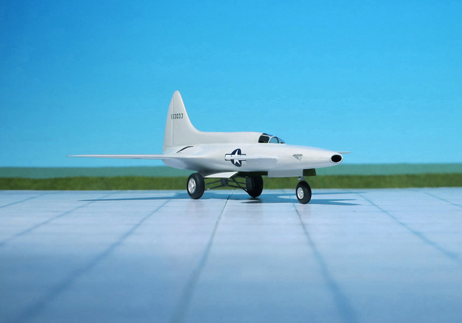
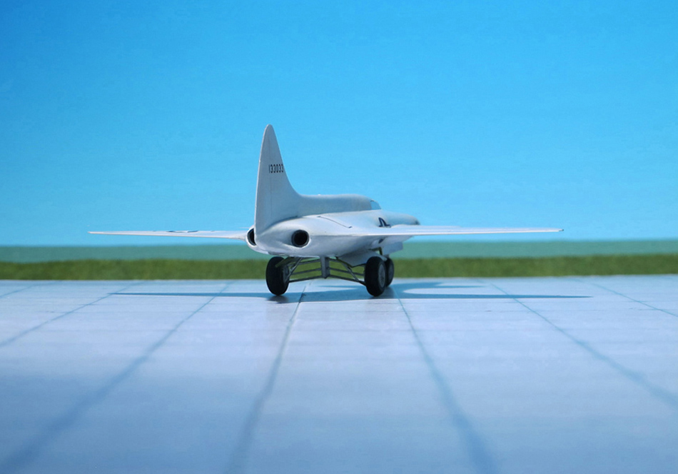
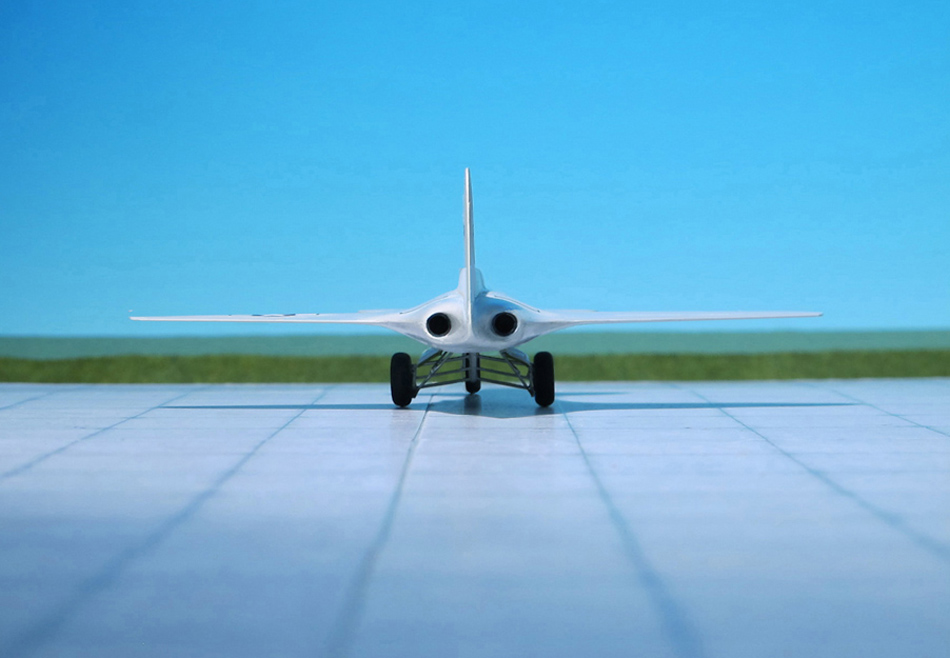
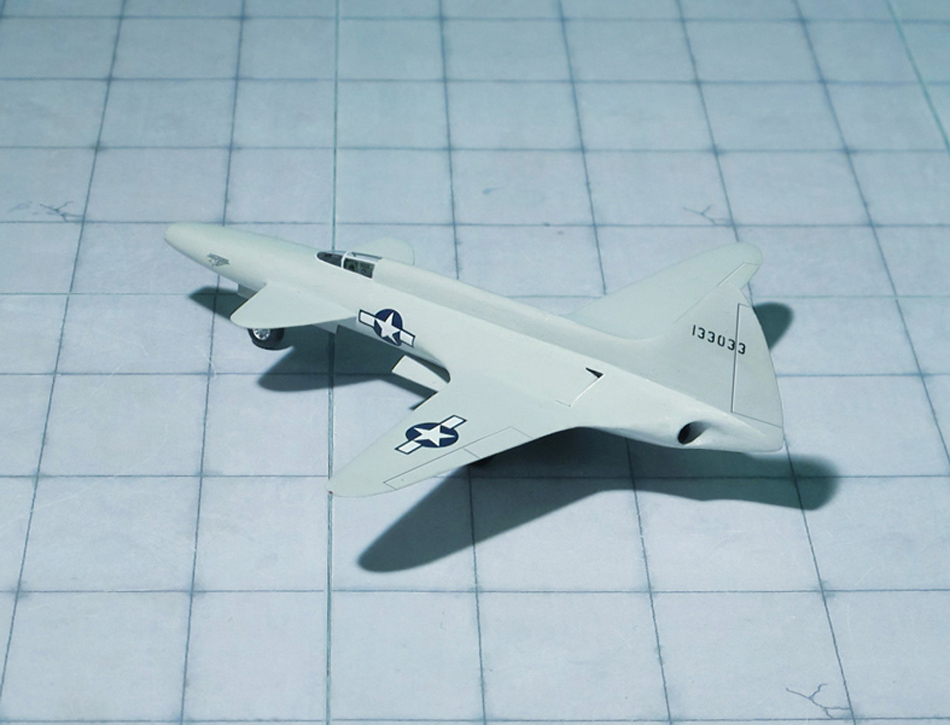
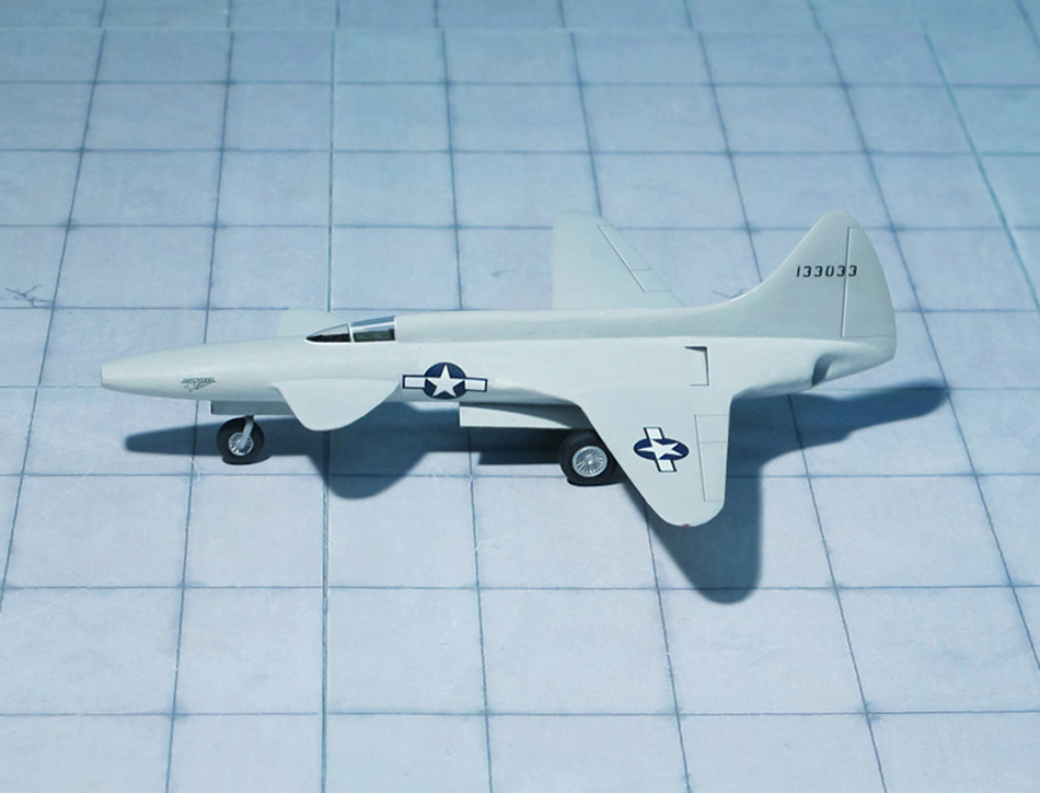
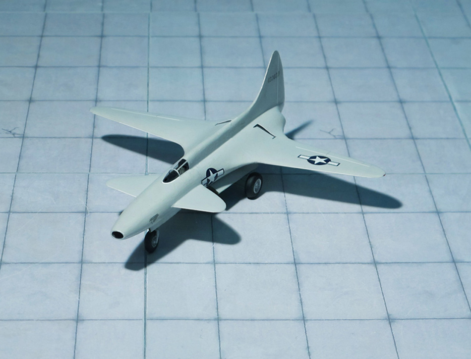
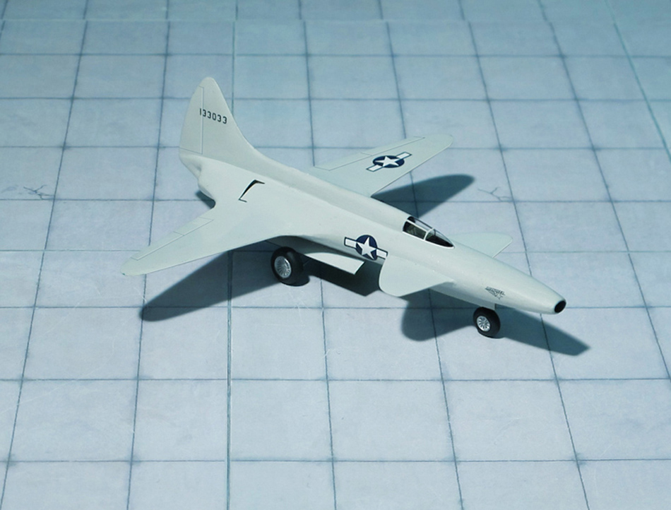
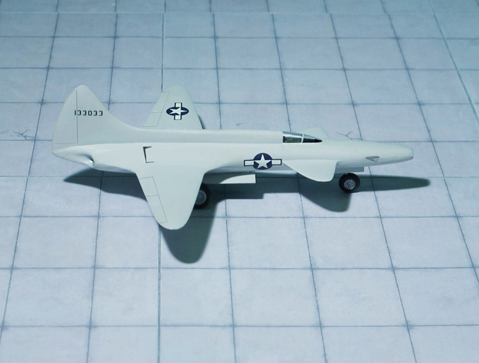
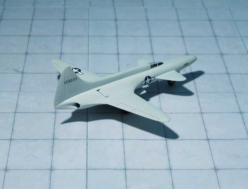
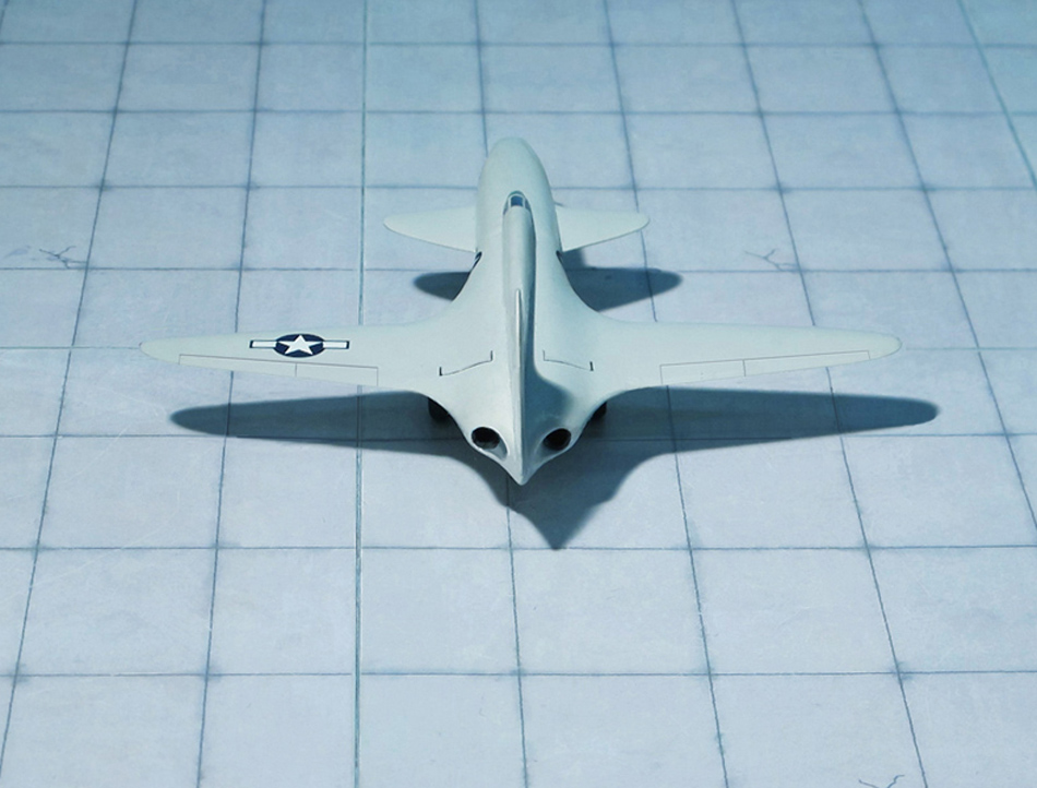
COMMENT: The Lockheed L-133 was an exotic design started in 1939 which was proposed to be the first jet fighter of the United States Army Air Forces (USAAF) during World War II.
The radical design was to be powered by two axial-flow turbojets with an unusual blended wing-body canard design capable of 612 mph in level flight. The USAAF rejected the 1942 proposal, but the effort speeded the development of the USAAF’s first successful operational jet fighter, the Lockheed P-80 Shooting Star, which did see limited service near the end of war. The P-80 was a less radical design with a single British-based Allison J33 engine, with a conventional tail, but it retained a wing which was the same shape as the outer wing sections of the Lockheed P-38 Lightning.
The Lockheed aviation company was the first in the United States to start work on a turbojet-powered aircraft, the L-133 design started in 1939 as a number of “Paper Projects” by engineers around Clarence L. „Kelly“ Johnson. By 1940 preliminary work on a company-financed turbojet-fighter had been started, which progressed to several different versions on the drawing board. In the meantime, Lockheed was working on an axial-flow L-1000 turbojet engine of their own design, which was intended to power the culmination of the twin-engine jet fighter project, the Model L-133-02-01.
Throughout World War II, the development of a jet-powered fighter had the potential to bring a decisive advantage in the air battles of the war; as history played out, only Germany built significant numbers of jet fighters before the war ended, but they reached service in the Luftwaffe too late to make a difference.
On March 30, 1942, Lockheed formally submitted the L-133-02-01 to the USAAF for consideration. Powered by two L-1000 turbojets and featuring a futuristic-appearing canard design with slotted flaps to enhance lift, the single-seat fighter was expected to have a top speed of 612 mph in level flight, but a range of only 310 mi.
The L-133 had a main wing shape that was essentially identical to the outer wing sections of the Lockheed P-38 Lightning. In many respects the L-133 was far ahead of its time, with futuristic features including: canard layout, blended wing-body planform, and two engines in a very low-drag integral fuselage location.
The USAAF considered the L-133 to be too advanced for the time, and did not pursue the project. The experience gained with the design served Lockheed well in the development of the USAAF’s first operational jet fighter, the P-80 Shooting Star. Although entering combat service after the war had ended, the P-80 was less advanced than the L-133. Because the USAAF didn’t give the L-133 project the go-ahead, the advanced engines intended for the L-133 had long pauses in their development. The most expedient engine choice for the P-80 thus became the Allison J33, based on British centrifugal compressor designs. The P-80 was a cheap-to-build single-engine aircraft with a conventional wing and tailplane design, not using the blended wing-body and canard layout of the L-133 (Ref.:24).
POWER PLANT: Two Allison V-1710-49/53 liquid-cooled engines, rated at 1,225 hp each
PERFORMANCE: 351 mph at 10,000 ft
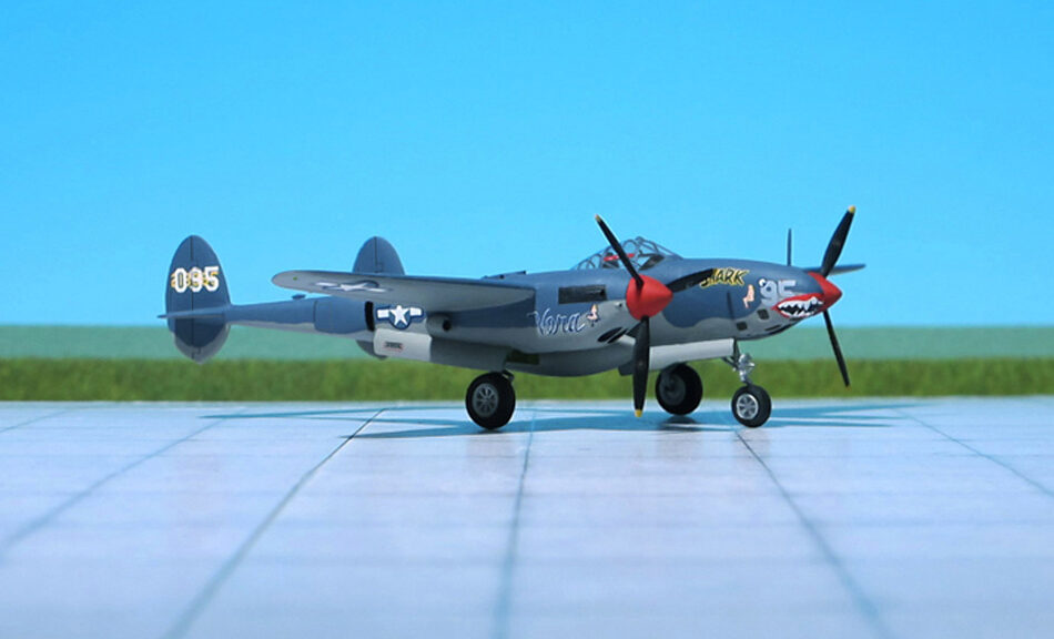
COMMENT: The Lockheed P-38 Lightning was an American single-seat, piston-engined fighter aircraft that was used during World War II. Developed for the United States Army Air Corps, the P-38 had distinctive twin booms and a central nacell containing the cockpit and armament. Along with its use as a general fighter, the P-38 was utilized in various aerial combat roles including as a highly effective fighter-bomber, a night-fighter and as a long-range escort fighter when equipped with drop tanks. The P-38 was also used as a bomber-pathfinder, guiding streams of medium and heavy bombers; or even other P-38s, equipped with bombs, to their targets. Used in the aerial reconnaissance role, the P-38 accounted for 90 percent of the aerial film captured over Europe.
Delivered and accepted Lightning production variants began with the P-38D model. The few “hand made” YP-38s initially contracted were used as trainers and test aircraft. There were no Bs or Cs delivered to the government as the USAAF allocated the ‘D’ suffix to all aircraft with self-sealing fuel tanks and armor. Many secondary but still initial teething tests were conducted using the earliest D variants.
The first combat-capable Lightning was the P-38E Lightning and its photo-recon variant the F-4, which featured improved instruments, electrical, and hydraulic systems. Part-way through production, the older Hamilton Standard Hydromatic hollow steel propellers were replaced by new Curiss Electric duraluminium propellers.
The first P-38E rolled out of the factory in October 1941and promptly filled the news wires of the world. Because of the versatility, redundant engines, and especially high speed and high altitude characteristics of the aircraft, as with later variants over a hundred P-38Es were completed in the factory.
After 210 P-38Es were built, they were followed, starting in February 1942, by the Lockheed P-38F, which incorporated racks inboard of the engines for fuel tanks or a total of 910 kg of bombs. Early variants did not enjoy a high reputation for maneuverability, though they could be agile at low altitudes if flown by a capable pilot, using the P-38’s forgiving stall characteristics to their best advantage. From the P-38F-15 model onwards, a “combat maneuver” setting was added to the P-38’s Fowler flaps which allowed the P-38 to out-turn many contemporary single-engined fighters at the cost of some added drag. However, early variants were hampered by high aileron control forces and a low initial rate of roll, and all such features required a pilot to gain experience with the aircraft, which in part was an additional reason Lockheed sent its representative to England, and later to the Pacific Theater.
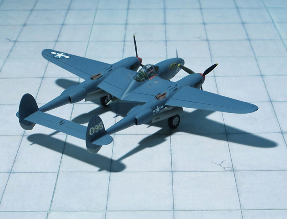
In March 1942 the first deliveries of the photoreconnaissance version Lockheed F-4 were made. Otherwise similar to the P-38E from which it was converted, the F-4 had the nose armament supplanted by four K-17 cameras for reconnaissance duties. A drift sight and auto pilot were standart in the photographic Lightnings, which were painted in cerulean blue. More than 100 F-4 reconnaissance aircraft based on the P-38E and 20 F-4A based on the P-38F were built.
The aircraft shown here belonged to the 12th Photo Reconnaissance Group, 15th Air Force, Mediterranean Theater (Ref.: 24).
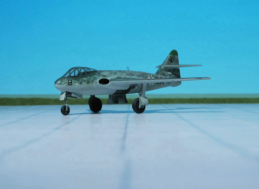
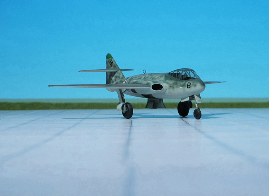
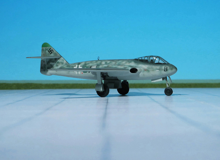
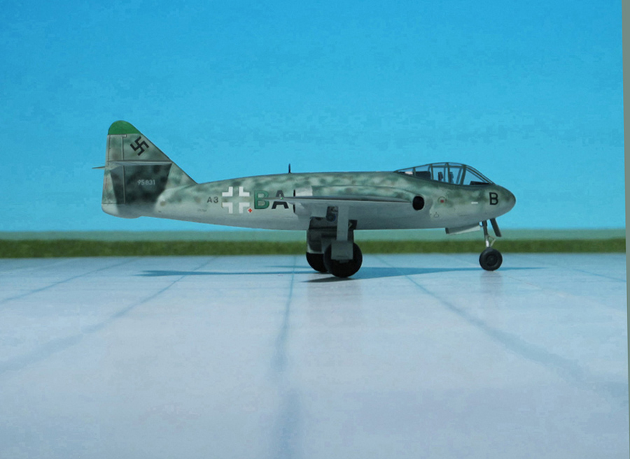
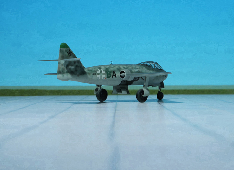
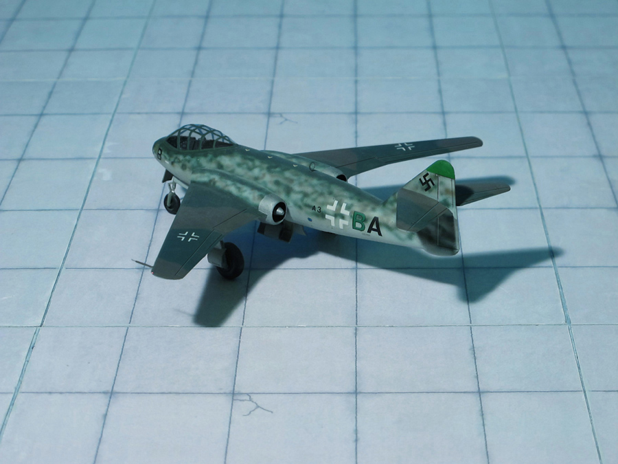
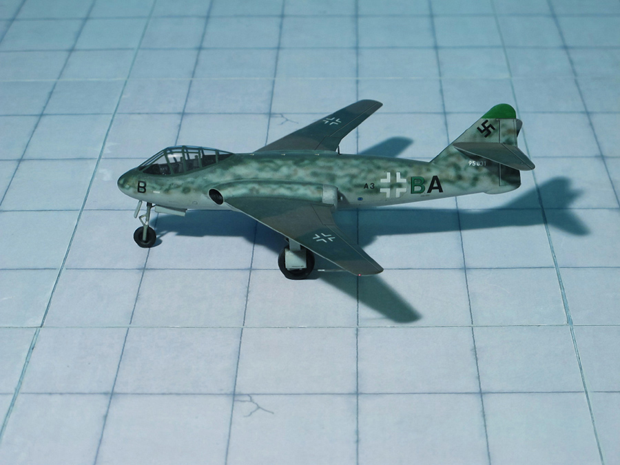
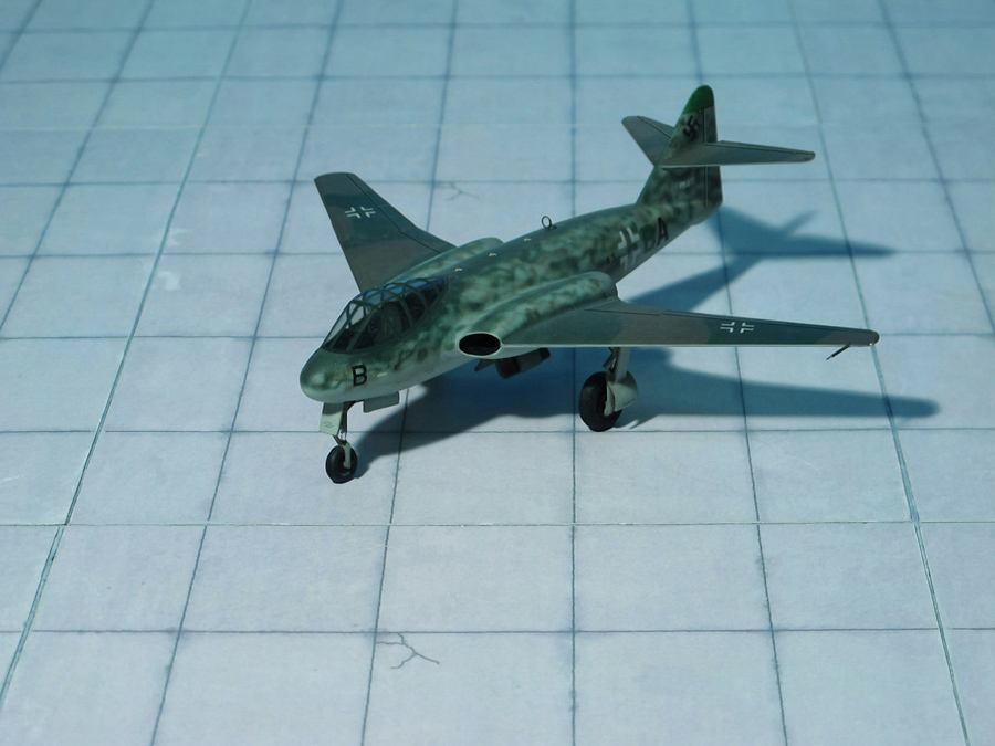
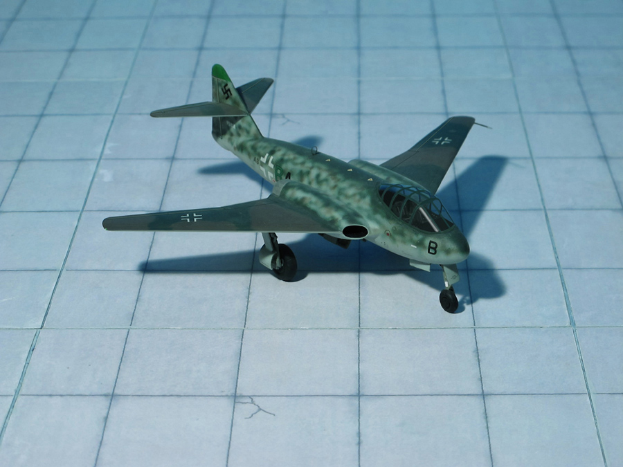
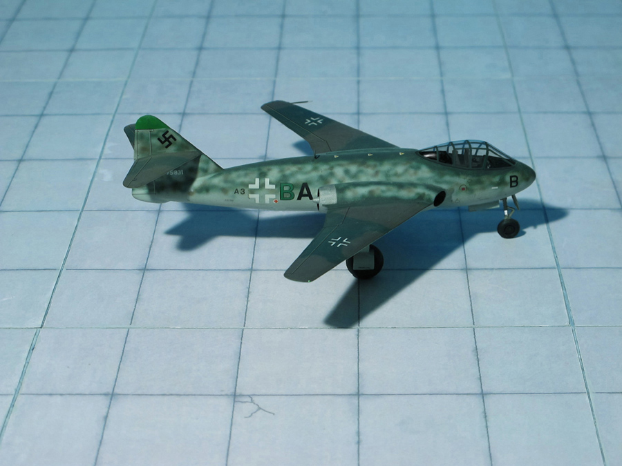
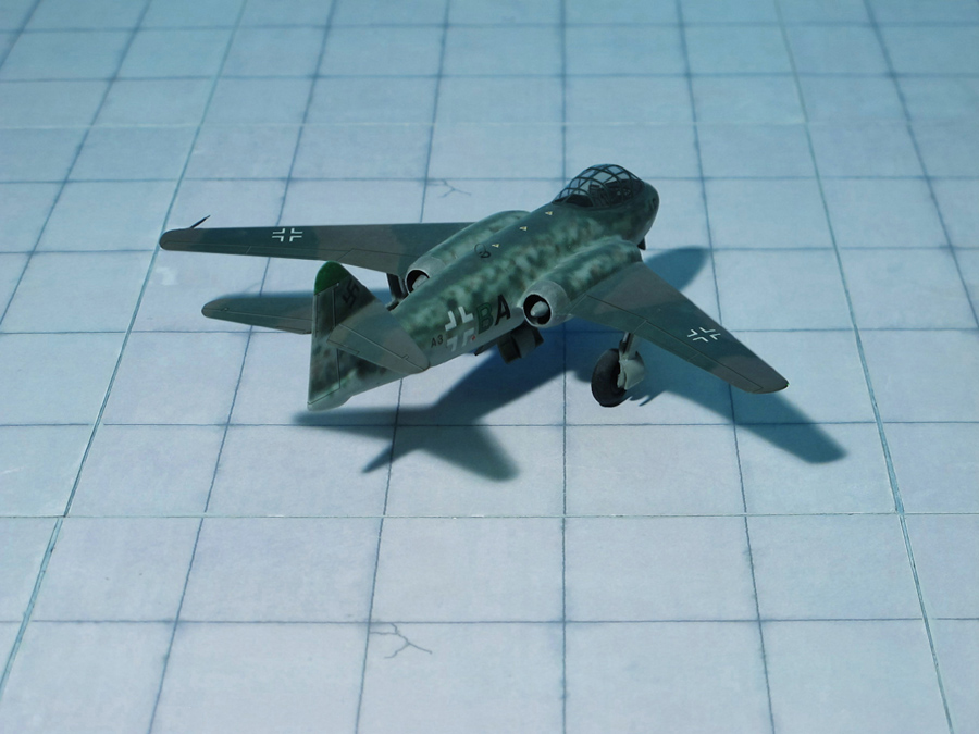
ACCOMMODATION: Crew of two (Pilot and radiooperator/navigator)
POWER PLANT: Two Heinkel-Hirth HeS 011 turbojet engines, rated at 1.300 kp thrust each
PERFORMANCE: 565 mph
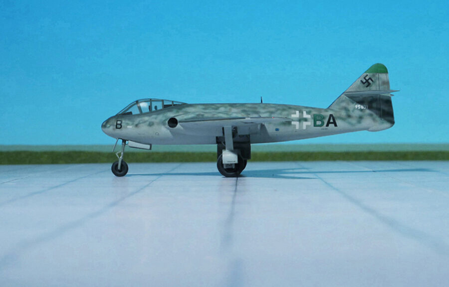
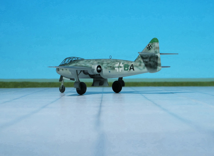
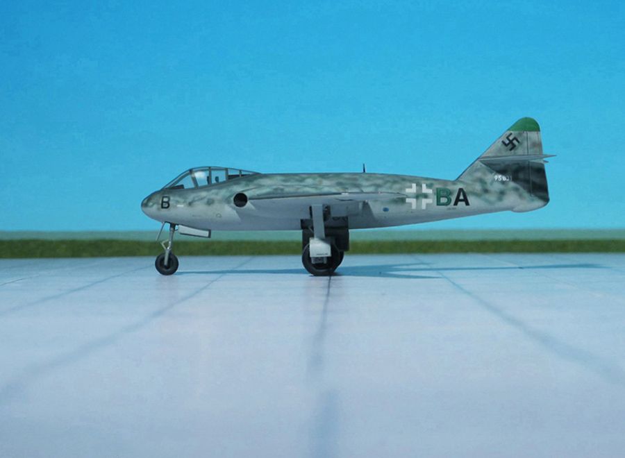
COMMENT: This project study of 11. April 1945 (Little note: less than four weeks before the total collaps of the “Third Reich”!!!!) for a two seat “Schnellbomber” (fast bomber) and “Zerstörer” (destroyer) constituted a further development of the Messerschmitt Me P.1099, Me P.1100 and Me P.1101 series of proposals of 1944 on the basis of the original in service Messerschmitt Me 262.
Whereas the basic fuselage, spacious cockpit and tail surfaces of the mentioned follow-up proposals were retained, the two Heinkel-Hirth HeS 011 turbojets were relocated into the wing root to which the new wings having a leading edge sweep of almost 40 degrees were attached. An interesting feature of the design was that the mainwheels were to retract inwards to rest vertically in the fuselage between the fore and aft fuel tanks. Exactly how this was to be accomplished with the turbojets in the way is not clear from the documents. Although the final form of the fuselage nose portion had not been decided, the end of the war brought an early end of the project (Ref.: 16).
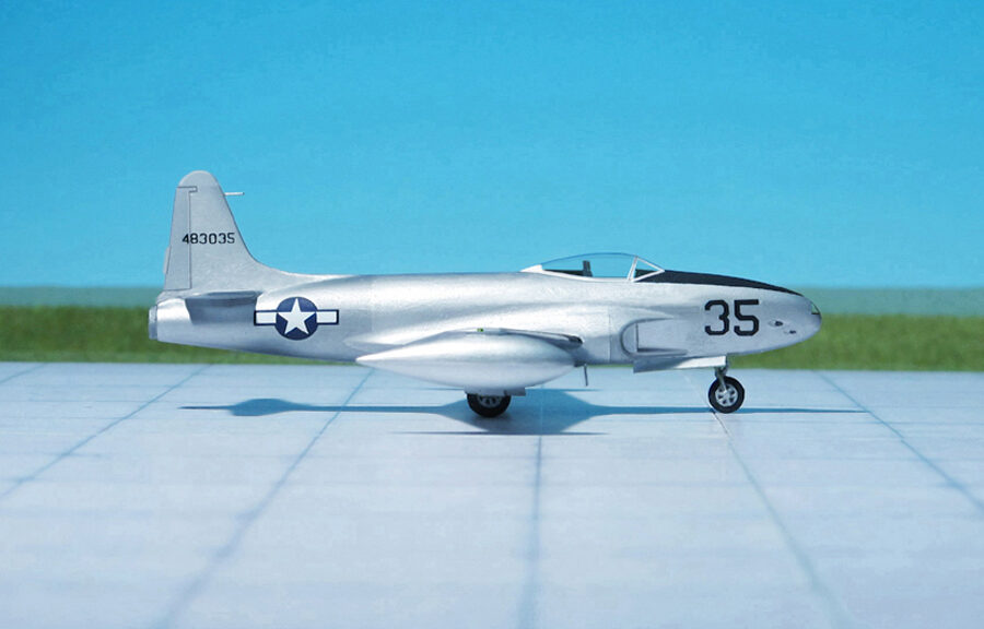
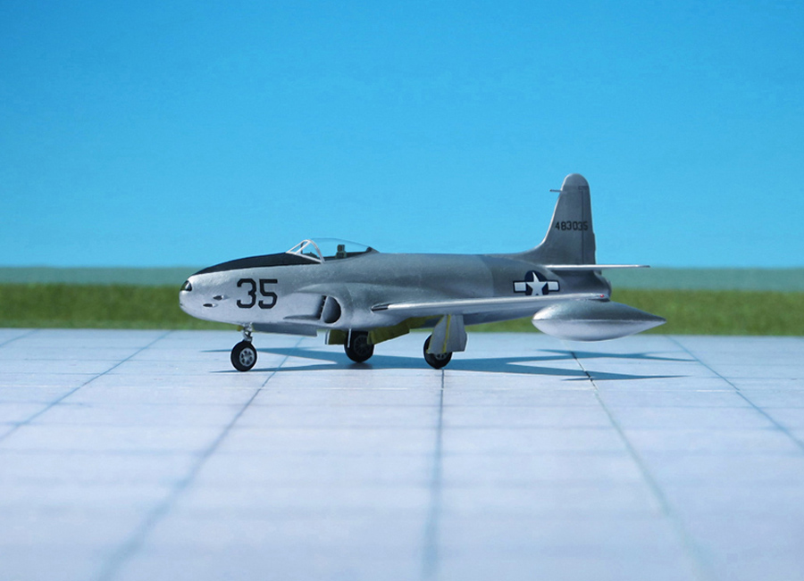
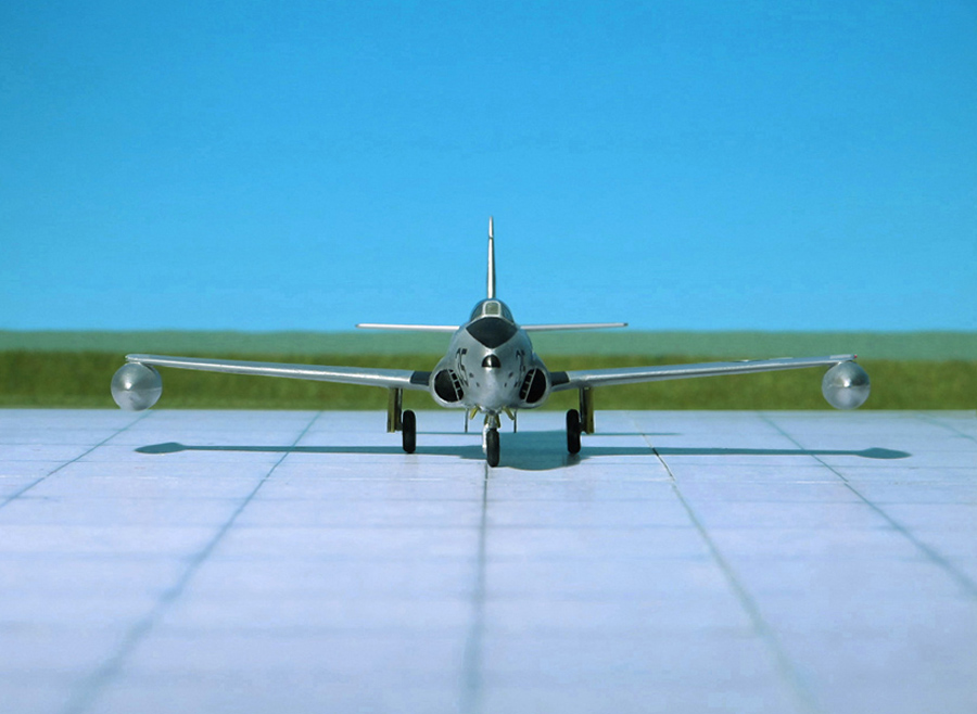
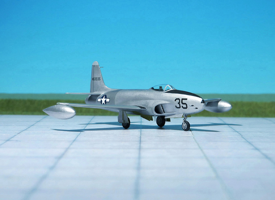
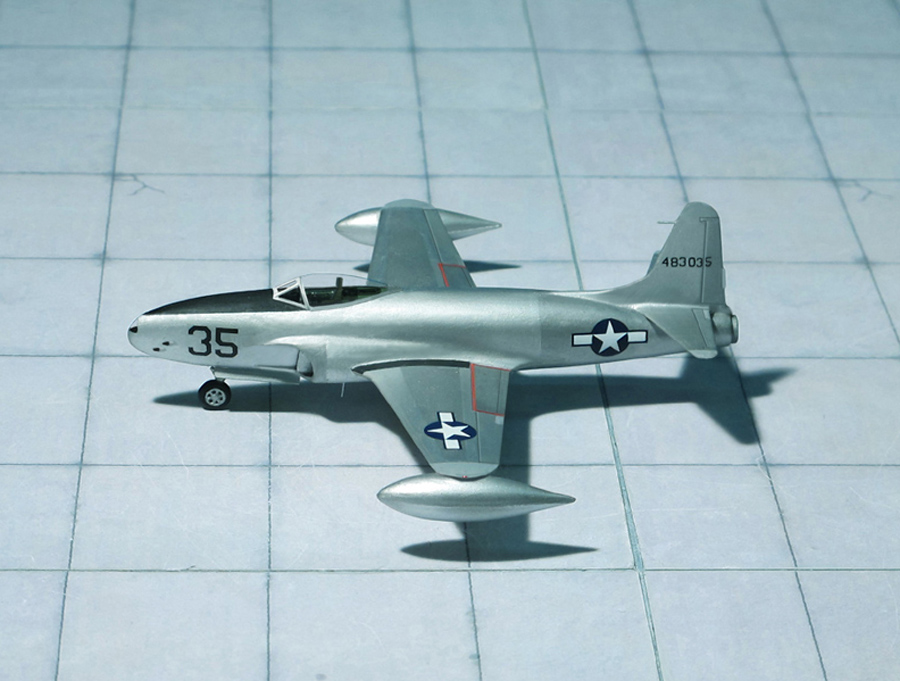
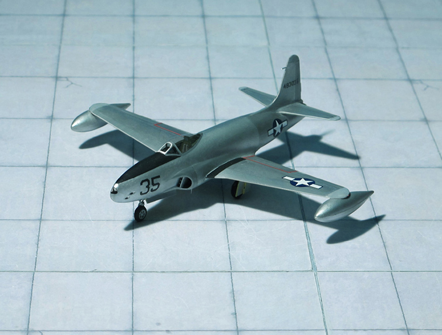
POWER PLANT: One Allison J-33-A-35 turbojet engine, rated at 2,100 kp thrust
PERFORMANCE: 492 mph at 40,000 ft
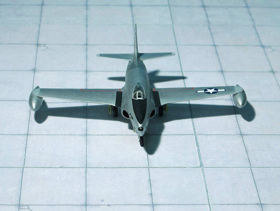
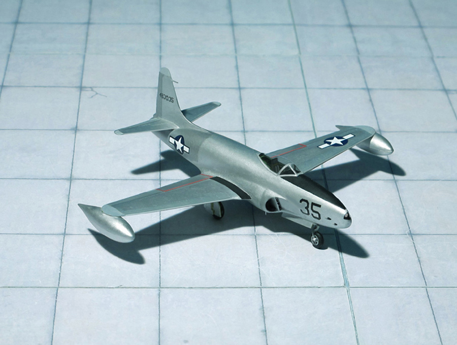
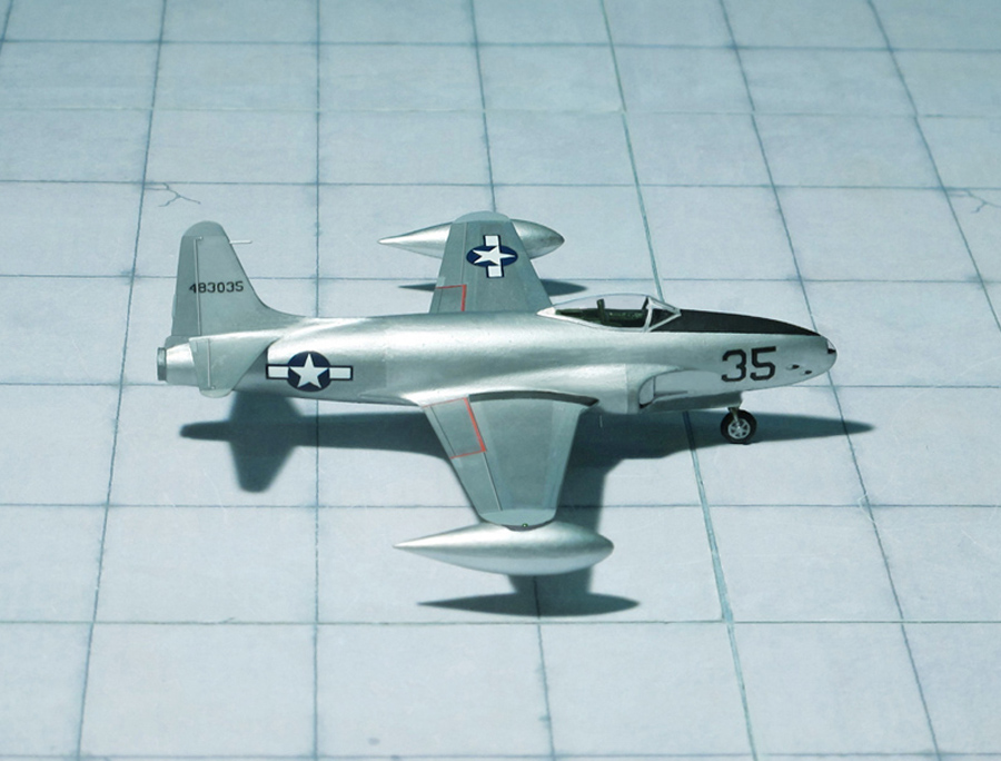
COMMENT: The Lockheed P-80 Shooting Star was the first jet fighter used operationally by the USAAF. Designed and built by Lockheed Aircraft Company in 1943 and delivered just 143 days from the start of the design process, production models were flying but not ready for service by the end of WW II. Designed with straight wings, the type saw extensive combat in Korea with the United States Air Force (USAF) as the Lockeed F-80.
The prototype XP-80 had a conventional all-metal airframe, with a slim low wing and tricycle landing gear. Like most early jets designed during World War II – and before the Allies captured German research data that confirmed the speed advantages of swept-wings – the XP-80 had straight wings, similar to previous propeller-driven fighters. It was the first operational jet fighter to have its engine in the fuselage, a format previously used in the pioneering German Heinkel He 178 V1 of 1939, and the later British Gloster E.28/39 Pioneer demonstrator of 1941. Other early jets generally had two engines because of their limited power, these being mounted in external necelles for easier maintenance. With the advent of more powerful British jet engines, fuselage mounting was more effective, and it was used by nearly all subsequent fighter aircraft.
Concept work on the XP-80 began in 1943 with a design being built around the blueprint dimensions of a British Halford H-1 B turbojet (later called the de Havilland Goblin), a powerplant to which the design team did not have actual access. Lockheed’s team, consisting of 28 engineers, was led by the legendary C. L. „Kelly“ Johnson. This teaming was an early product of Lockheed’s Skunk Works, which surfaced again in the next decade to produce a line of high-performance aircraft.
The impetus for development of the P-80 was the discovery by Allied intelligence of the Messerschmitt Me 262 ‘Schwalbe’ (‘Swallow’) in spring 1943, which had made only test flights of its own first quartet (the V1 through V4 airframes) of design prototypes at that time, all fitted with retracting tailwheel landing gear. After receiving documents and blueprints comprising years of British jet aircraft research, the commanding General of the Army Air Forces, Henry H. Arnold, believed an airframe could be developed to accept the British-made jet engine, and the Materiel Command’s Wright Field research and development division tasked Lockheed to design the aircraft. With the Germans and British clearly far ahead in development, Lockheed was pressed to develop a comparable jet in as short a time as possible. Kelly Johnson submitted a design proposal in mid-June and promised that the prototype would be ready for testing in 180 days. The Skunk Works team, beginning 26 June 1943, produced the airframe in 143 days, delivering it to Muroc Army Airfield on 16 November.
The project was so secret that only five of the more than 130 people working on it knew that they were developing a jet aircraft, and the British engineer who delivered the Goblin engine was detained by the police because Lockheed officials could not vouch for him. After the engine had been mated to the airframe, foreign object damage during the first run-up destroyed the engine, which delayed the first flight until a second engine (the only other existing) could be delivered from Britain.
The first prototype was nicknamed „Lulu-Belle“ (also known as „the Green Hornet” because of its paint scheme). Powered by the replacement Halford H1 taken from the prototype de Havilland Vampire jet fighter, it first flew on 8 January 1944.The donated British jet program data had no doubt proved invaluable. In test flights, the XP-80 eventually reached a top speed of 502 mph at 20,480 ft, making it the first turbojet-powered USAAF aircraft to exceed 500 mph in level flight, following the August 1944 record flight of 502 mph by a special high-speed variant of the Republic P-47J Thunderbolt. Contemporary pilots, when transitioning to pioneering jets like the Shooting Star, were unused to flying at high speed without a loud reciprocating engine and had to learn to rely on the airspeed indicator.
The second prototype, designated XP-80A, was designed for the larger General Electric I-40 engine (an improved J31, later produced by Allison as the J33). Two aircraft were built. one was nicknamed the Gray Ghost after its “pearl gray” paint scheme, while the second aircraft was left unpainted for comparison of flight characteristics, became known as the Silver Ghost. The XP-80A’s first test flight was unimpressive, but most of the problems with the design were soon addressed and corrected in the test program. Initial opinions of the XP-80A were not positive and the aircraft were primarily testbeds for larger, more powerful engines and air intake design, and consequently were larger and 25% heavier than the XP-80.
The Shooting Star began to enter service in late 1944 with 12 pre-production YP-80As. A 13th YP-80A was modified to the sole F-14 photo reconnaissance model and lost in a December crash.
The initial production order was for 344 P-80As after USAAF acceptance in February 1945. A total of 83 P-80s had been delivered by the end of July 1945 and 45 assigned to the 412th Fighter Group (later redesignated the 1st Fighter Group) at Muroc Arma Air Field. Four were sent to Europe for operational testing (demonstration, familiarization, and possible interception roles), two to England and two to Italy, but after two accidents, one in England and one in Italy, the YP-80A was temporarily grounded. So the Lockheed Shooting Star saw no actual combat during the conflict.
After the war, the USAAF compared the P-80 and Messerschmitt Me 262 concluding, “Despite a difference in gross weight of nearly 900 kg, the Me 262 was superior to the P-80 in acceleration, speed and approximately the same in climb performance. The Me 262 apparently has a higher critical Mach number, from a drag standpoint, than any current Army Air Force fighter”.
Production oft he Shooting Star continued after the war, although wartime plans for 5,000 were quickly reduced to 2,000. A total of 1,714 single-seat F-80A, F-80B, F-80C, and RF-80s were manufactured by the end of production in 1950, of which 927 were F-80Cs (including 129 operational F-80As upgraded to F-80C-11-LO standards). However, the two-seat TF-80C, first flown on 22 March 1948, became the basis for the T-33 trainer, of which 6,557 were produced (Ref.: 24).
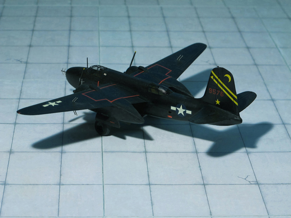
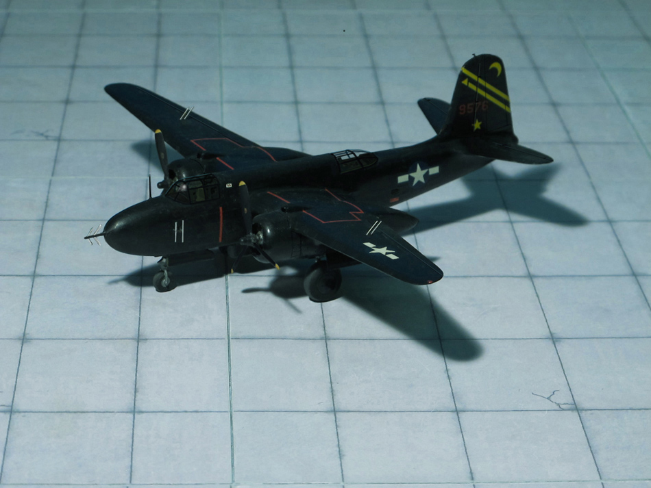
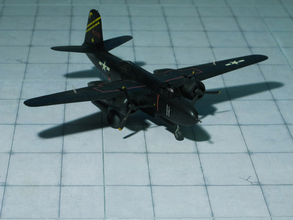
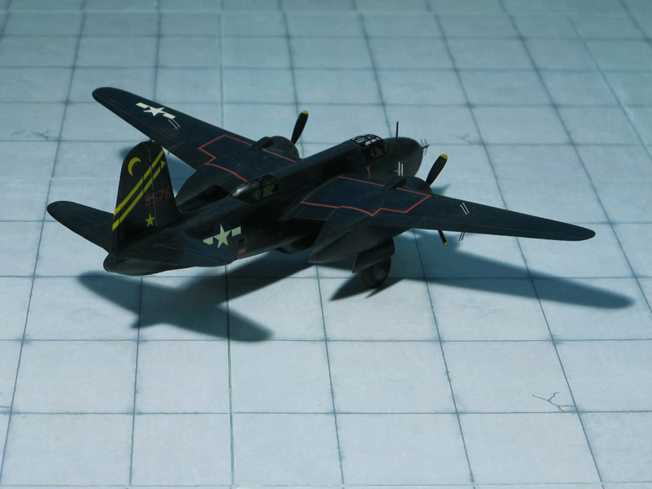
POWER PLANT: Two Wright R-2600-23 Twin Cyclone radial engines, rated at 1,600 hp each
PERFORMANCE: 329 mph at 14,500 ft
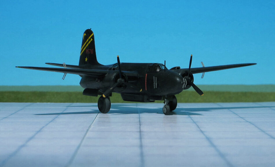
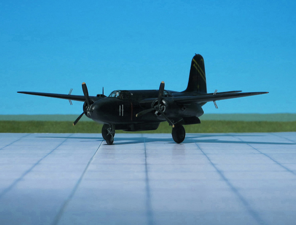
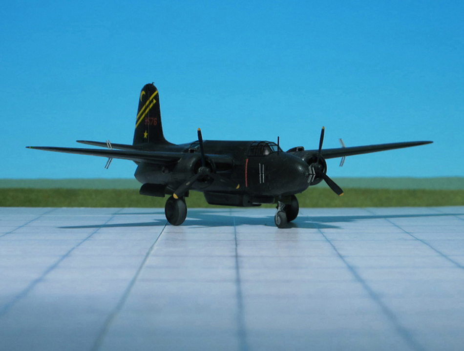
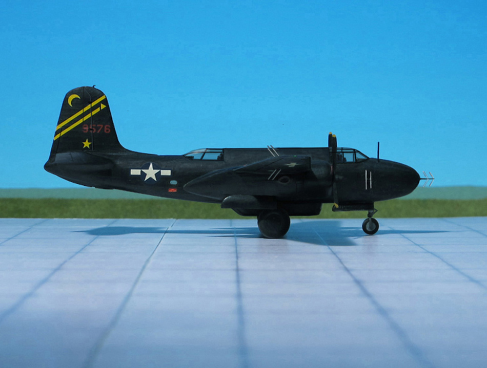
COMMENT: The Douglas A-20 Havoc (company designation DB-7) is an American medium bomber, attack aircraft, night intruder, night fighter, and reconnaissance aircraft of WW II.
Designed to meet an Army Air Corps requirement for a bomber, it was ordered by France for their air force before the USAAC decided it would also meet their requirements. French DB-7s were the first to see combat; after the fall of France the bomber, under the servce name Boston continued with the Royal Air Force. From 1941, night fighter and intruder versions were given the service name Havoc. In 1942 USAAF A-20s saw combat in North Africa.
It served with several Allied air forces, principally the United States Army Air Forces (USAAF), the Soviet Air Forces (VVS), Soviet Naval Aviation (AVMF), and the Royal Air Forces (RAF). A total of 7,478 aircraft were built, of which more than a third served with Soviet units.
In most British Commonwealth air forces, the bomber variants were known as Boston, while the night fighter and intruder variants were named Havoc. The exception was the Royal Australian Air Force (RAAF), which used the name Boston for all variants.
The USAAF used the P-70 designation to refer to the night fighter variants.
In October 1940, the USAAC felt a need for long-range fighters more than attack bombers. As a result, sixty of the production run of A-20s were converted to P-70 night fighters, all delivered by September 1942. They were equipped with SCR-540 radar (a copy of the British AI Mk. IV), the glazed nose often being painted black to reduce glare and hide the details of the radar set, and had four 20 mm forward-firing cannon, each provided with 120 rounds, in a tray in the lower part of the bomb bay, while the upper part held an additional fuel tank with a capacity of 250 US gallons . In 1943, 13 A-20Cs and 51 A-20Gs were converted to Douglas P-70A. Differences were to be found in the armament, with the 20mm cannon package replaced by an A-20G gun nose with six .50 caliber guns installed, the SCR-540 radar installation being carried in the bomb bay with the vertical-plane, twin-dipole “arrowhead” transceiving antenna protruding between the nose guns. Further P-70 variants were produced from A-20G and J variants. The singular airframe P-70B-1 (converted from an A-20G) and subsequent P-70B-2s (converted from A-20Gs and Js) had American centimetric radar (SCR-720 or SCR-729) fitted.
The P-70s and P-70As saw combat only in the Pacific during World War II and only with the USAAF. The P-70B-1 and P-70B-2 aircraft never saw combat but served as night fighter aircrew trainers in the US in Florida and later in California. All P-70s were retired from service by 1945 (Ref.: 24).
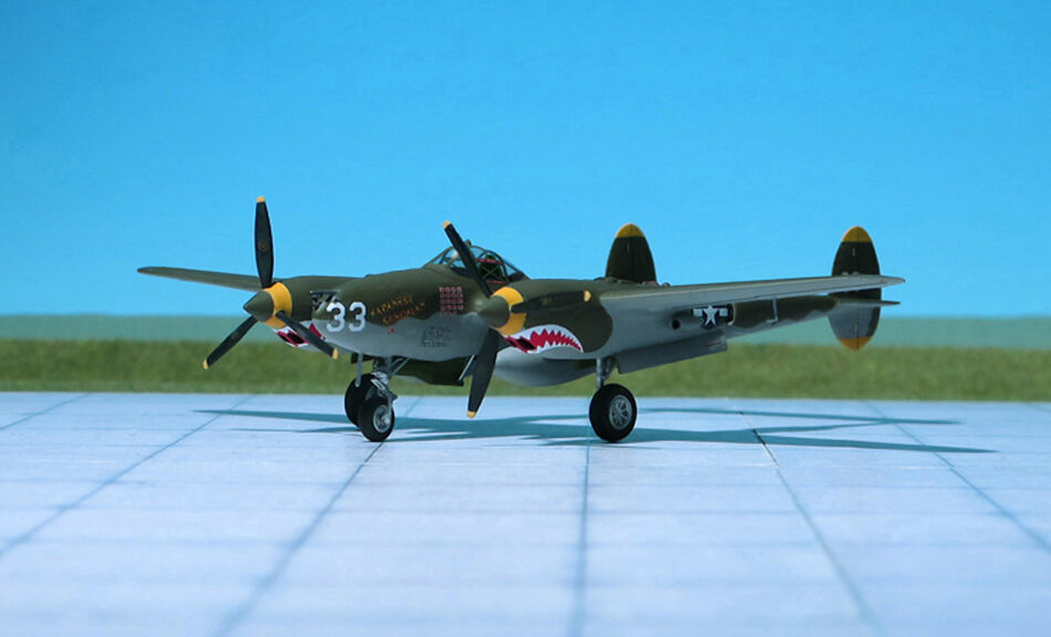
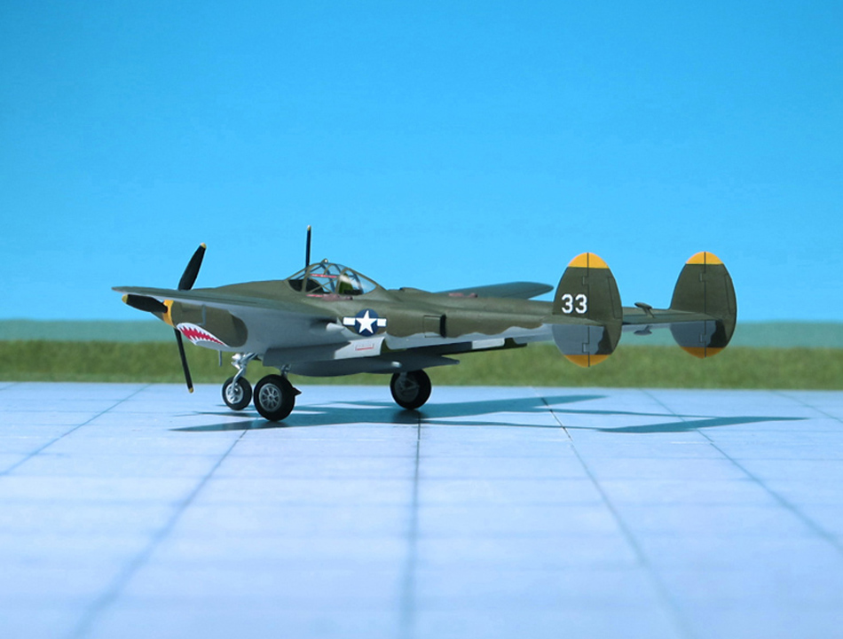
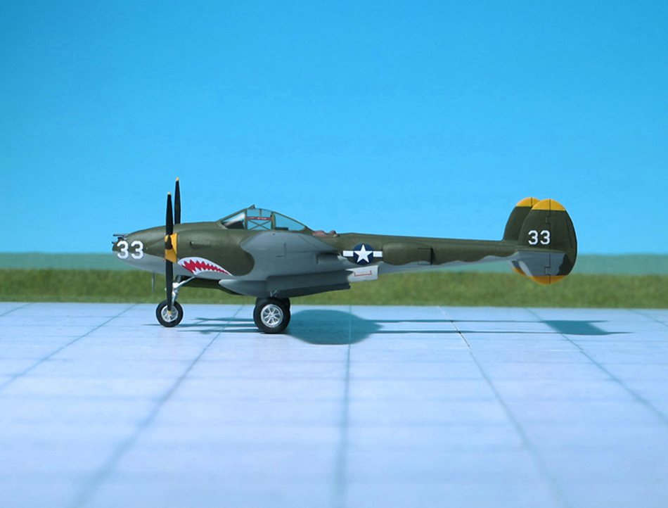
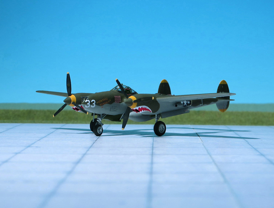
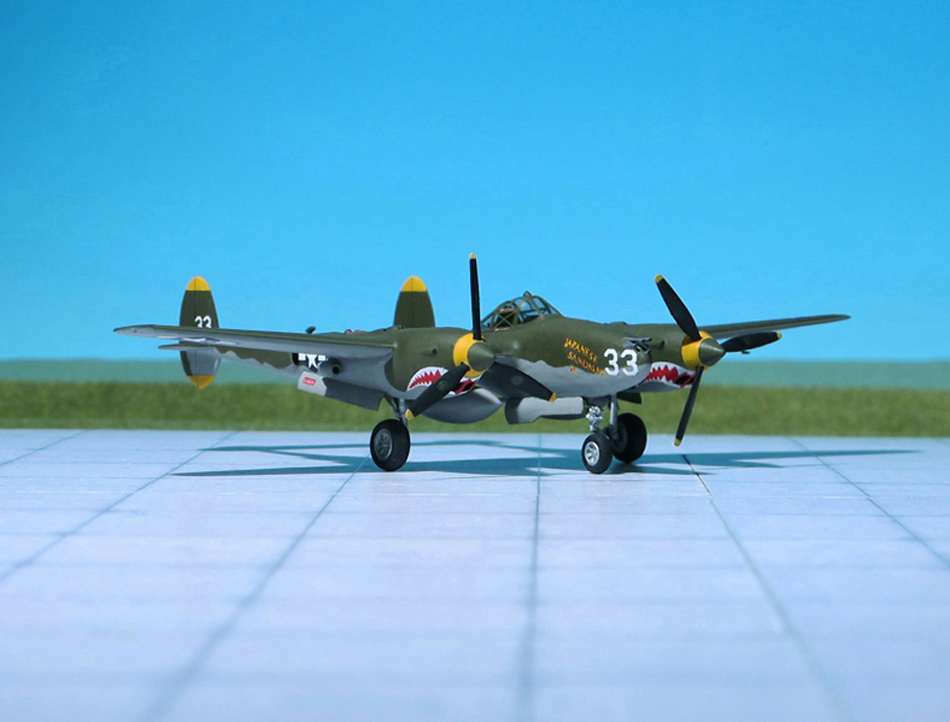
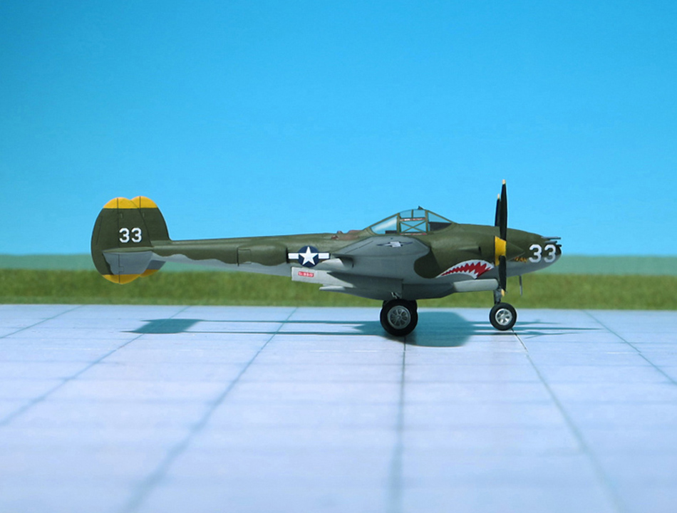
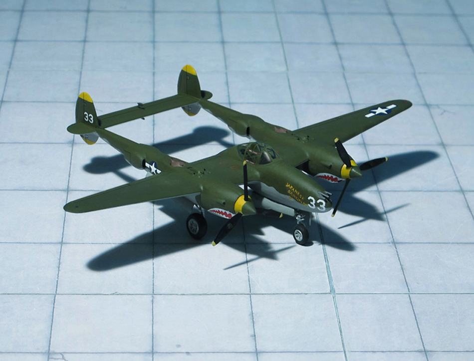
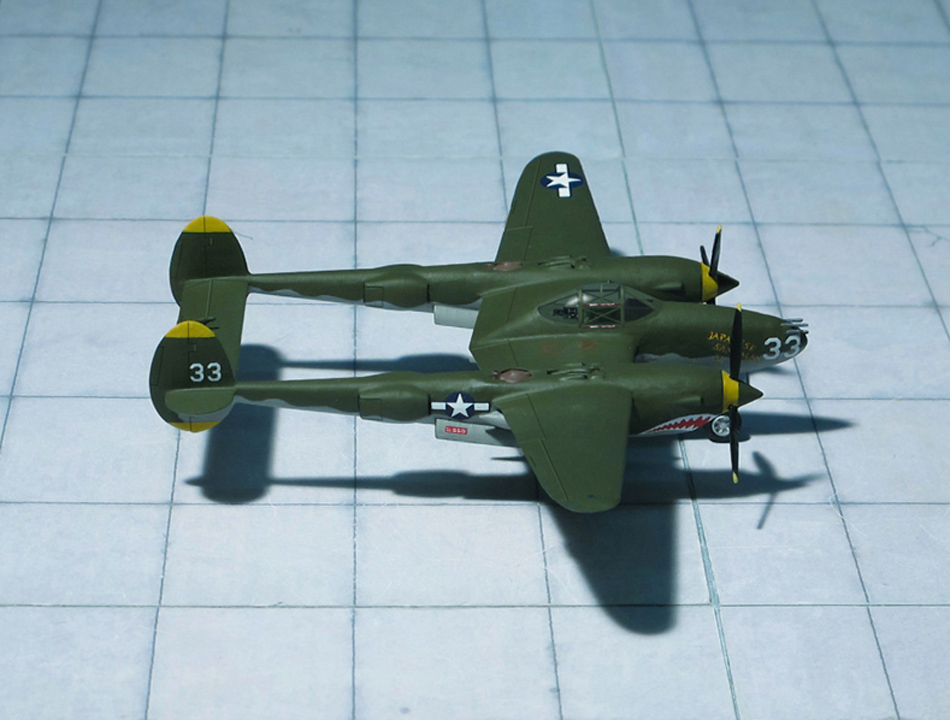
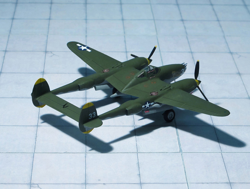
POWER PLANT: Two Allison V-1710-49/53 liquid-cooled engines, rated at 1,225 hp each
PERFORMANCE: 390 mph at 25,000 ft
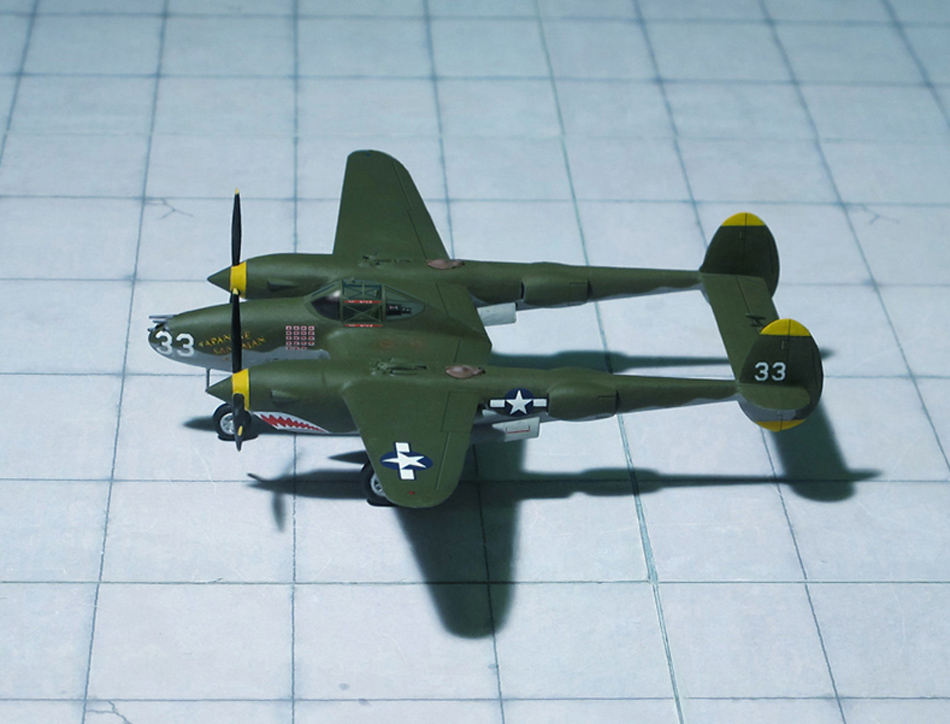
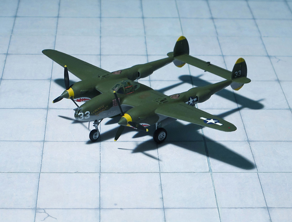
COMMENT: The Lockheed P-38 Lightning was an American piston-engined fighter aircraft of WW II. Developed for the United States Army Ai Corps, the P-38 had distinctive twin booms and a central nacelle containing the cockpit and armament. Allied propaganda claimed it had been nicknamed the fork-tailed devil („Gabelschwanz-Teufel“) by the Luftwaffe and “two planes, one pilot” by the Japanese. Along with its use as a general fighter, the P-38 was utilized in various aerial combat roles including as a highly effective fighter-bomber, a night-fighter, and as a long-range escort fighter when equipped with drop tanks. The P-38 was also used as a bomber-pathfinder, guiding streams of medium and heavy bomber; or even other P-38s, equipped with bombs, to their targets. Used in the aerial reconnaissance role, the P-38 would account for 90 percent of the aerial film captured over Europe.
The P-38 was used most successfully in the Pacific Theater of Operations (PTO) and was the primary long-range fighter of Unites States Army Air Forces until the introduction of large numbers of North American P-51D „Mustang“ toward the end of the war.
Lockheed designed the Model 22 in response to a February 1937 specification from the United States Arma Air Corps (USAAC). Circular Proposal X-608 was a set of aircraft performance goals for a twin-engine, high-altitude aircraft having the tactical mission of interception and attack of hostile aircraft at high altitude. The Lockheed design team chose twin booms to accommodate the tail assembly, twin engines, and turbo-superchargers, with a central nacelle for the pilot and armament.
The Lockheed design incorporated tricycle undercarriage and a bubble canopy, and featured two 1,000 hp turbosupercharged 12-cylinder Allison V-1710 engines fitted with counter rotating propellers to eliminate the effect of engine torque, with the turbochargers positioned behind the engines, the exhaust side of the units exposed along the dorsal surfaces of the booms. The aircraft was the first American fighter to make extensive use of stainless steel and smooth, flush-riveted butt-jointed aluminum skin panels It was also the first military airplane to fly faster than 400 mph in level flight.
Lockheed won the competition on June 1937 with its Model 22 and was contracted to build a prototype officially designated XP-38. Construction began in July 1938, and the XP-38 first flew on 27 January 1939. After speed testing the Air Corps ordered 13 YP-38s on April 1939, these few “hand made” YP-38’s were used as trainers and test aircraft.
Delivered and accepted production variants began with the P-38D model but the first combat-capable Lightning, as the aircraft was officially named by the USAAC by adopting the British service name, was the P-38E and its photo-reconnaissance variant the F-4
The first P-38E rolled out of the factory in October 1941. Because of the versatility, redundant engines, and especially high speed and high altitude characteristics of the aircraft, as with later variants over a hundred P-38Es were completed in the factory or converted in the field to a photoreconnaissance variant, the F-4, in which the guns were replaced by four cameras. Most of these early reconnaissance Lightnings were retained stateside for training, but the F-4 was the first Lightning to be used in action in April 1942.
After 210 P-38Es were built, they were followed, starting in February 1942, by the P-38F, the first truly operational Lightning. It incorporated racks inboard of the engines for fuel tanks or a total of 910 kg of bombs. 527 machines of this subtype were buit, including several variants. Lightnings of this type took part in their first large-scale operations during the North-African campaign, in November 1942, where mixed success was encountered. The twin engines restricted manoeuverability to some extent and it was unique among fightersof WW II in employing a wheel control instead of a conventional stick, a feature which may also have resulted in reduced ease of manoeuvre. Nevertheless, it proved an effective bomber destoyer and had a sensational zoom climb that could rarely be matched.
The Lockheed P-38F Lightning had also entered service in the Pacific area. Technical difficulties associated with intercooler operations in tropical conditions prevented the Lightning from entering service until the end of 1942, however, the first major engagement with Japanese aircraft occuring on December, when the 39th Fighter Squadron claimed 15 destroyed without loss (the model shown here is a P-38F of the 39th Fighter Squadron, 35th Fighter Group).
During production a continous series of improvements were being developed by Lockheed, some of which remained experimental but others being adopted for production. Among the most important in the latter category were long-range drop tanks and manoeuvring flaps. In early 1942, all P-38 carried the same long-range 75-US gal drop tanks as the Bell P-39 Aircobra and Curtiss P-40 Warhawk, one each side between the fuselage and nacelles. But Lockheed soon developed its own 150-US gal tank, and eventually 300-US gal versions, of laminar flow design. Stressing the wing section two such tanks could be carried by all variants from the P-38F onwards. To demonstrate the capability oft he Lightning with drop tanks, a P-38F was used late in 1942, to make an endurance flight lasting over 13 hrs and covering 4.677 km, with enough fuel remaining for more than 161 km. Thus, Lightning’s ability to fly long ranges, carrying two drop tanks, now proved especially useful and the P-38 became the most-preferred fighter type operating in the Pacific area.
After production of 2,410 P-38F, -G and –H and corresponding reconnaissance variants the production switched over to the most built Lockheed P-38J and –L Lightnings (Ref.: 3, 9, 24).
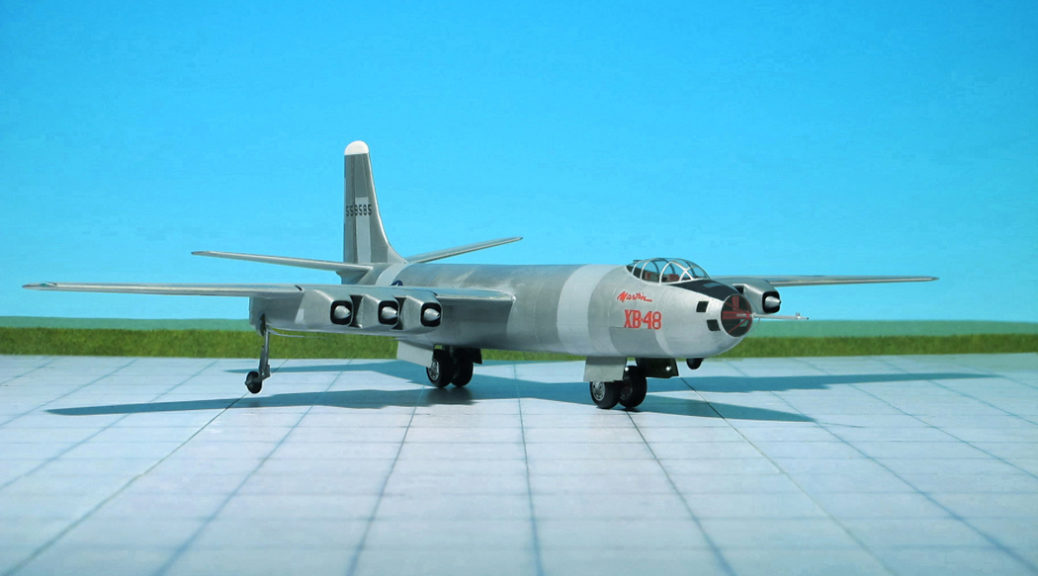
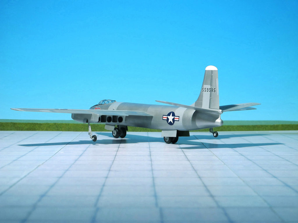
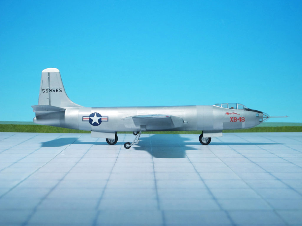
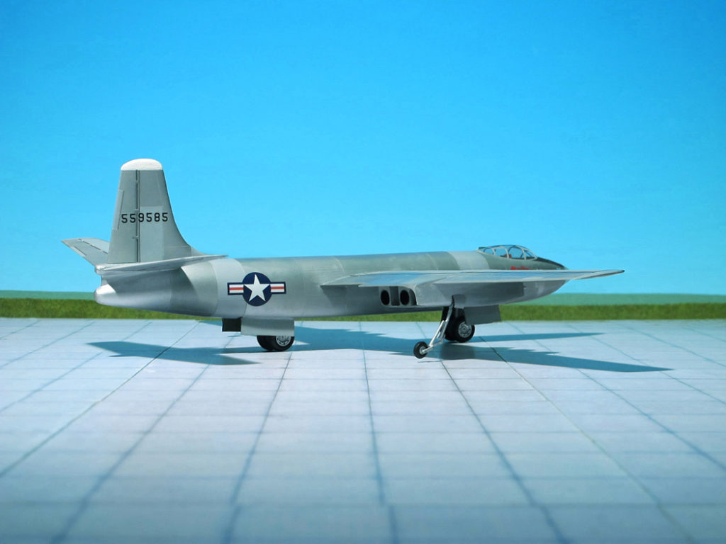
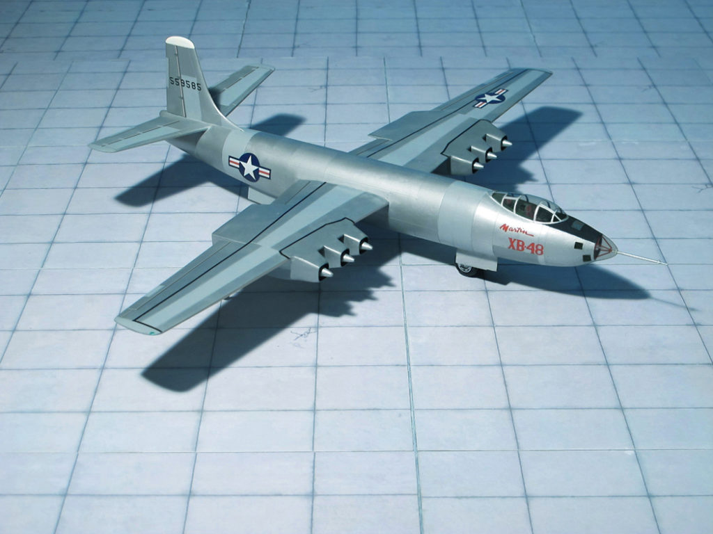
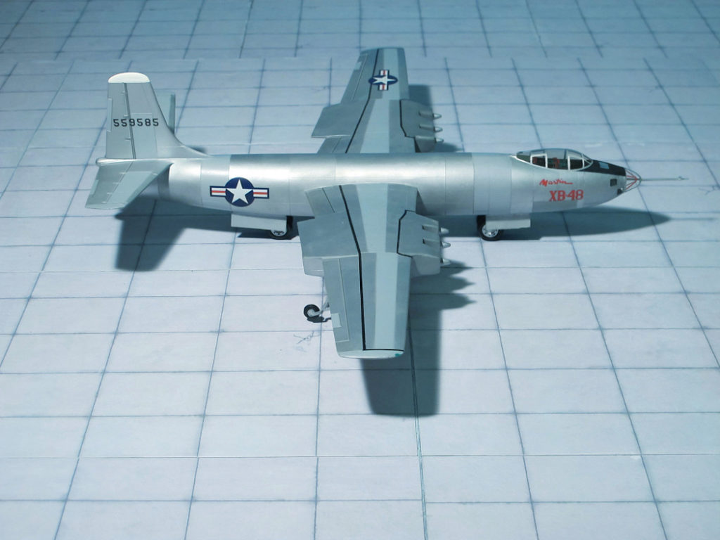
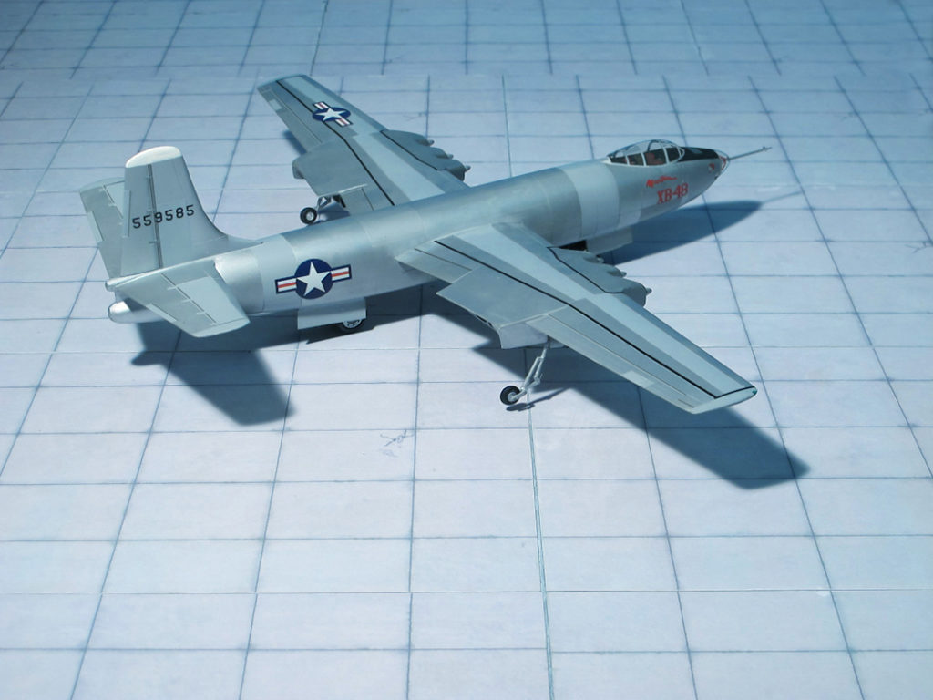
POWER PLANT: Six General Electric J35 turbojet engines, rated at 1.734 kp each
PERFORMANCE: 523 mph at 35,000 ft
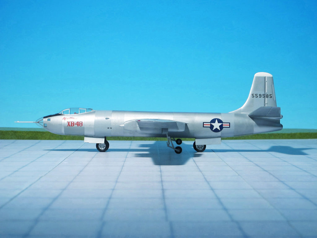
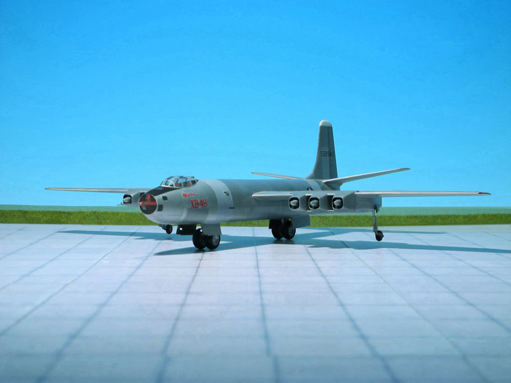
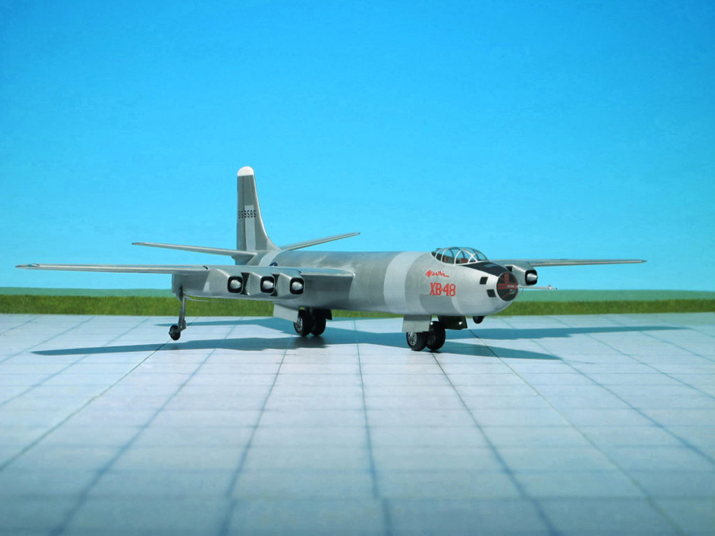
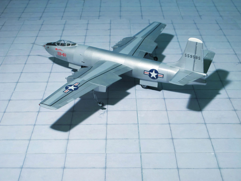
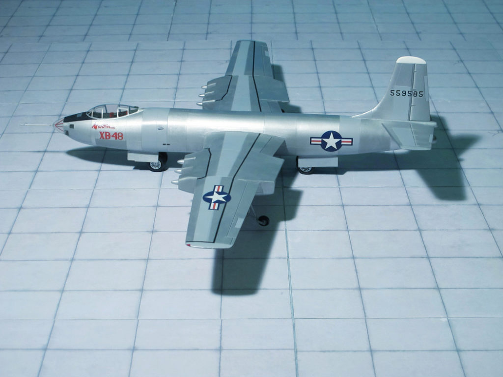
COMMENT: The Martin XB-48 was an American medium jet bomber developed in the mid-1940s. It competed with the Boeing B-47 “Stratojet”, which proved to be a superior design, and was largely considered as a backup plan in case the B-47 ran into development problems. It never saw production or active duty, and only two prototypes were built.
In 1944, the U.S. War Department was aware of aviation advances in Germany and issued a requirement for a range of designs for medium bombers weighing from 80,000 lb (36,287 kg) to more than 200,000 lb (90,718 kg). Other designs resulting from this competition, sometimes named “the class of ’45”, included the North American XB-45 and the Convair XB-46. Production orders finally went to the North American B-45 “Tornado”, and even this airplane served only for a couple of years before again being replaced by the much more modern Boeing B-47 “Stratojet”, although the B-45 had enough “utility” built in to maintain a niche as a reconnaissance aircraft.
In retrospect, the “class of ’45” were transitional aircraft, combining the power of turbojets with the aeronautical knowledge of World War II. The XB-48 was no exception, as its round fuselage and unswept wings showed a distinct influence of Martin’s B-26 “Marauder” medium bomber. Still, where the B-26 had enough thrust with two massive 18-cylinder radial engines, the XB-48 needed no less than six of the new jet engines.
Although the pictures make it look as if the aircraft had three engine nacelles under each wing, the jet engines were actually clustered in a pair of flat three-engined nacelles with an intricate system of air ducts between the engines, intended to facilitate cooling. At the time of the XB-48’s design, jet propulsion was still in its infancy.
The XB-48 was the first aircraft designed with bicycle-type tandem landing gear, which had previously been tested on a modified B-26. The wing airfoil was too thin to house conventional landing gear mechanisms. The main landing gear was in the fuselage and small outriggers located on each wing were used to balance the aircraft.
The XB-48 made its first flight on 22 June 1947, a 37-minute, 117 km hop from Martin’s Baltimore, Maryland plant to NAS Patuxent River, Maryland, but blew all four tires on its fore-and-aft mounted undercarriage on landing when the test pilot applied heavy pressure to the specially-designed, but very slow to respond, insensitive air-braking lever.
In 1948 the Martin XB-48 program was cancelled (Ref.: 24).
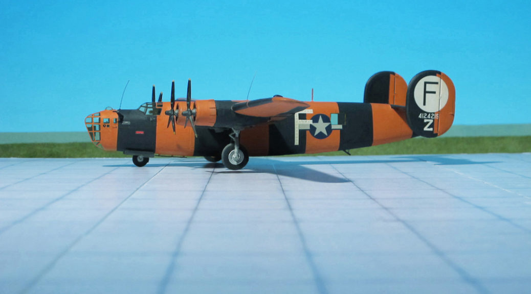
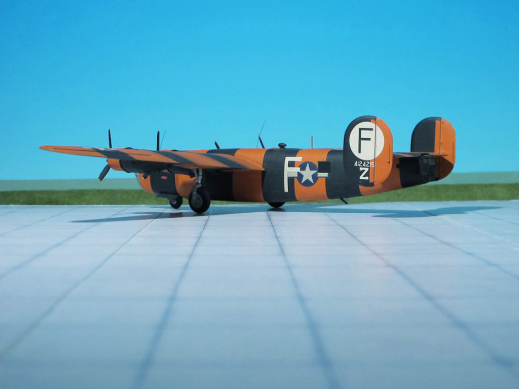
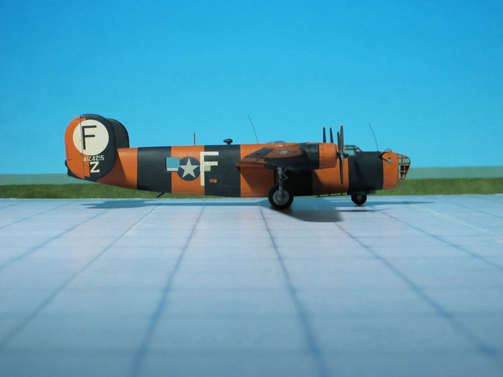
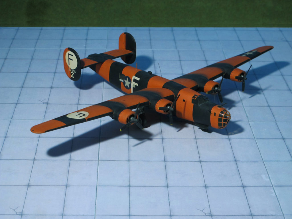
POWER PLANT: Four Pratt & Whitney R-1830-43 Twin Wasp radial engines, rated at 1,200 hp each
PERFORMANCE: 303 mph at 25,000 ft
COMMENT: The Consolidated B-24 Liberator was an American heavy bomber, designed by Consolidated Aircraft of San Diego, California. It was known within the company as the Model 32, and some initial production aircraft were laid down as export models designated as various LB-30s, in the Land Bomber design category.
The B-24 was used extensively in WW II. It served in every branch of the American armed forces as well as several Allied air forces and navies. It saw use in every theater of operations. Along with the Boeing B-17 Flying Fortress, the B-24 was the mainstay of the US strategic bombing campaign in the Western European theater. Due to its range, it proved useful in bombing operations in the Pacific Area, including the bombing of Japan. Long-range anti-submarine Liberators played an instrumental role in closing the Mid-Atlantic gap in the Battle oft he Atlantic.
The Consolidated B-24D Liberator was the first mass-produced series. The B-24D was the Liberator III in British service. It entered US service in early 1942. It had turbocharged engines and increased fuel capacity. Three more 12.7 mm machine guns brought the defensive armament up to 10 machine guns. At 27,000 kg (29.76 short tons) maximum takeoff weight, it was one of the heaviest aircraft in the world.
First model produced on a large scale; ordered from 1940 to 1942, as a Consolidated B-24C with better Pratt & Whitney R-1830-43 supercharged engines. The B-24D model was initially equipped with a remotely operated and periscopically sighted Bendix belly turret, as the first examples of the Boeing B-17E Flying Fortress and some early models of the North American B-25 Mitchell medium bomber had used, but this proved unsatisfactory in service and was discontinued after the 287th aircraft. Production aircraft reverted to the earlier manually operated “tunnel” mounting with a single 12.7 mm machine. The tunnel gun was eventually replaced by the Sperry ball turret, which had also been adopted by the later Boeing B-17E Fortresses, but made retractable for the Liberator when not in use as the ventral area of its fuselage was very close to the ground on landing. In late B-24Ds, “cheek” guns mounted on either side of the forward nose, just behind the framed “greenhouse” nose glazing were added.
Between 1940 and 1945 in total 18,188 B-24 of various subtypes had been built, The number of B-24D Liberator amounted 2,696 aircraft, of which 2,381 planes were built by Consolidated, San Diego, 305 planes by Consolidated, Fort Worth, and 10 examples by Douglas, Tulsa, Oklahoma.
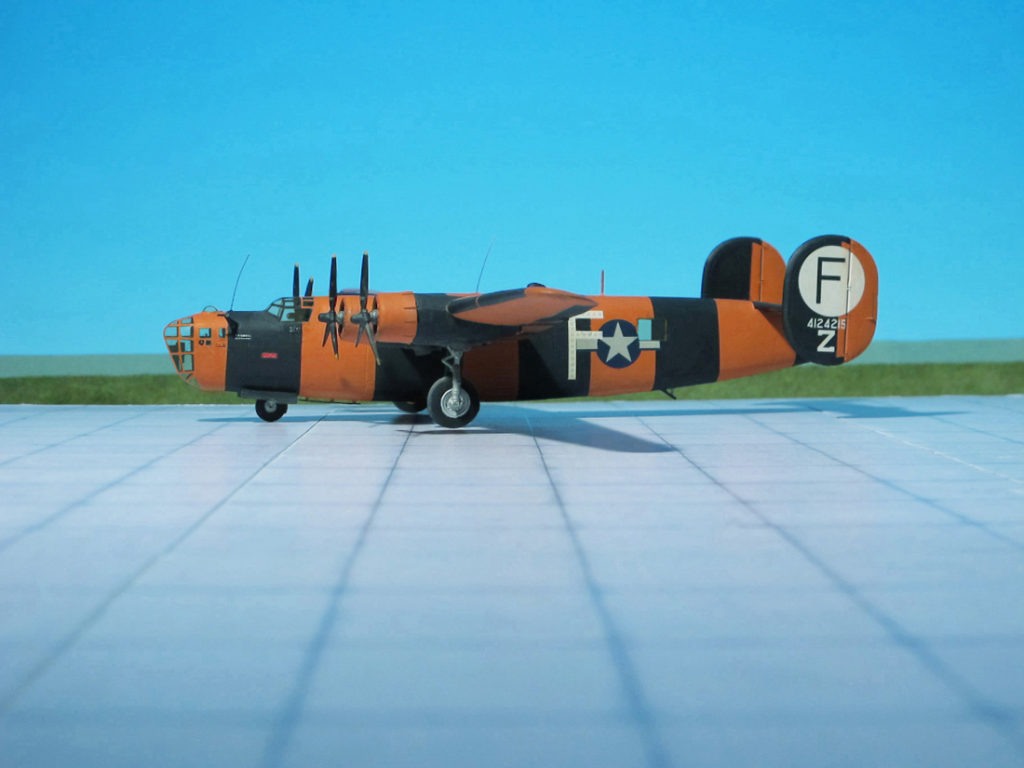
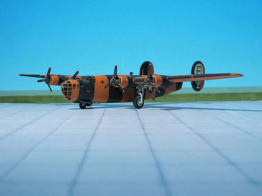
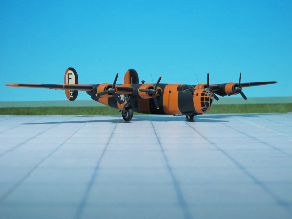
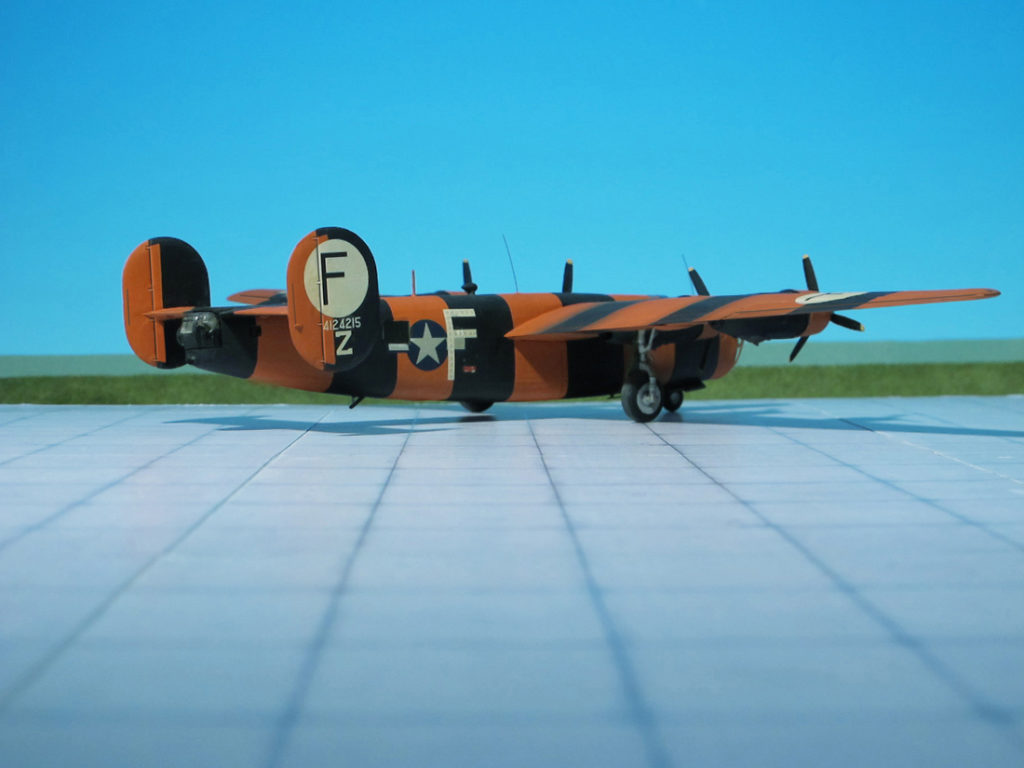
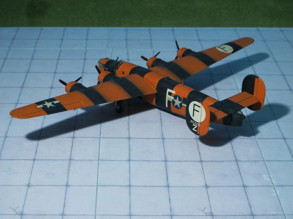
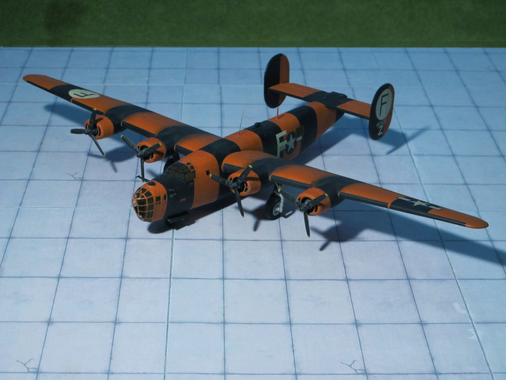
The Consolidated B-24D Liberator shown here, BuAer # 41-24215, was originally an aircraft of the 409th BS, 93rd BG, 8th AF in Europe and named ‘Lucky Gordon’, sometimes called just ‘Lucky’. On Aug 01th, 1943 the aircraft took part in the Ploesti oil refinery raid, diverting to Sicily, Italy. After returning to the European Theatre of Operations (ETO) and further missions it was declared war weary and renamed ‘Dogpatch Raider’ and served with the 703rd BS, as a high visibility assembly ship for the 445th BG (H), flying from RAF Tibenham, Norfolk. The large letter “F” on her fuselage, the Group’s call letter, contained bright navigation lights for dim lighting conditions (Ref.: 24).
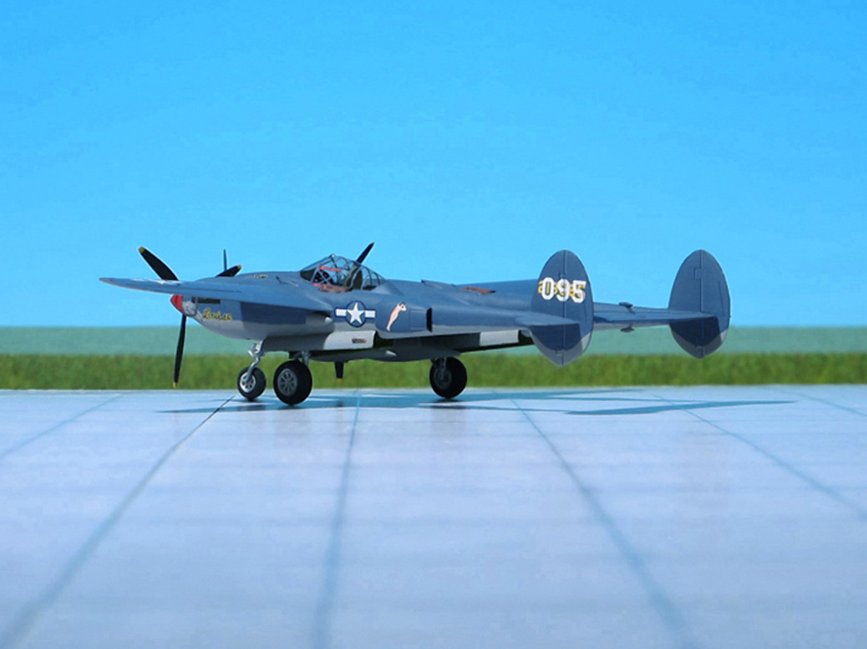
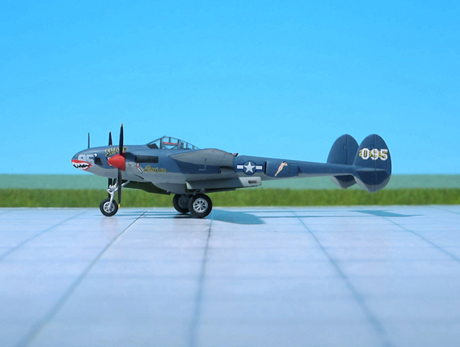
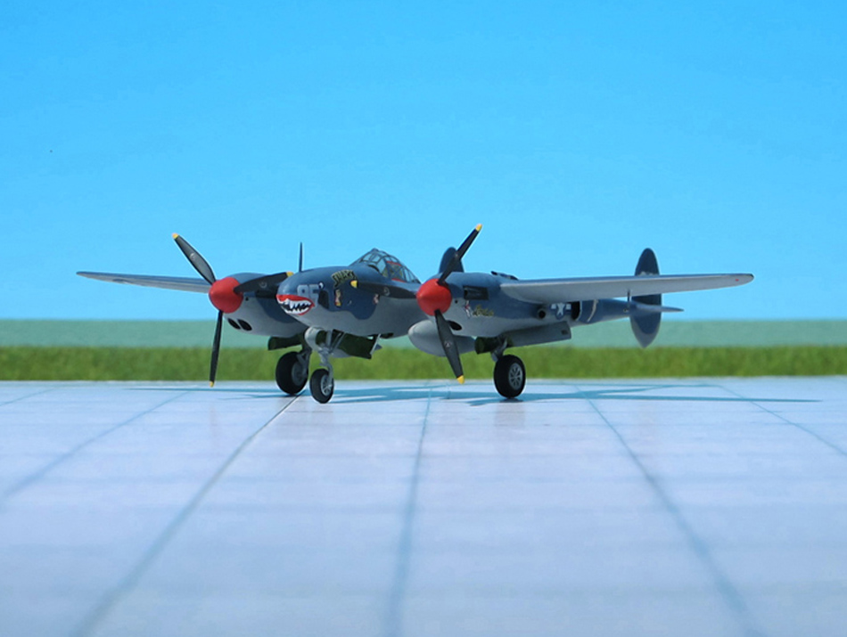
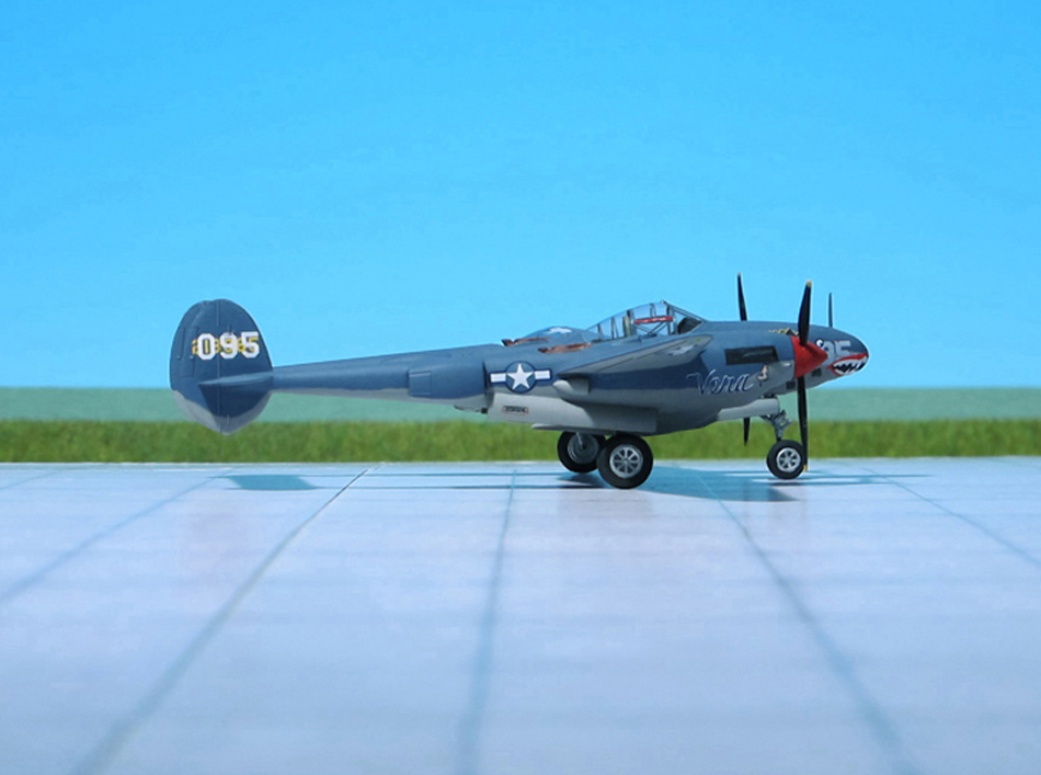
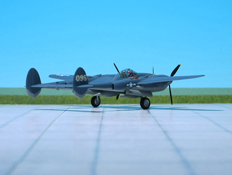
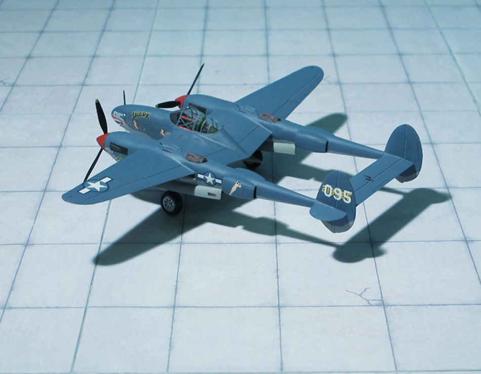
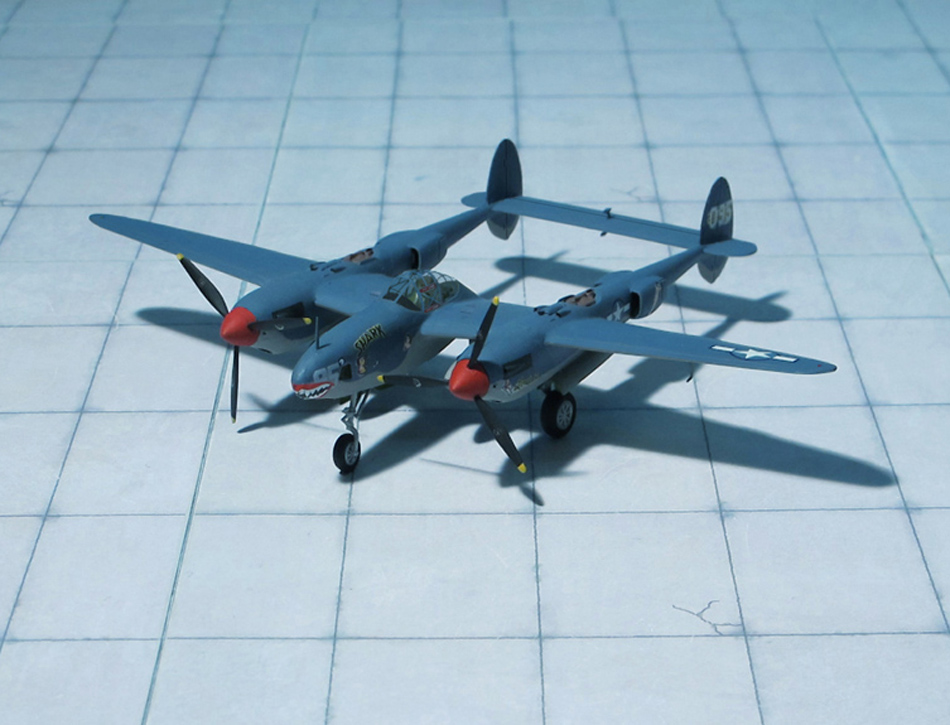
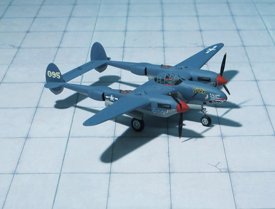
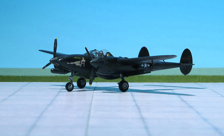
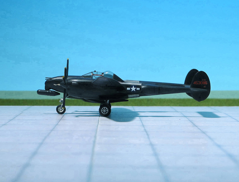
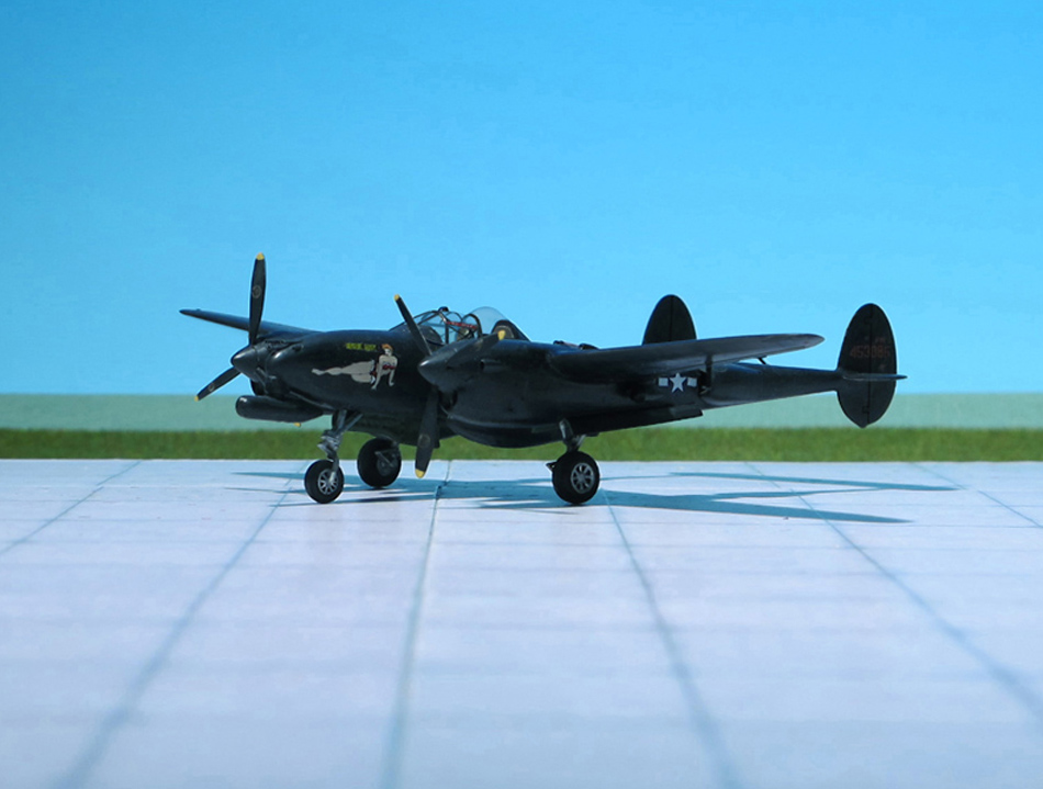
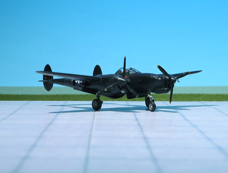
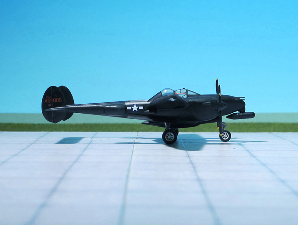
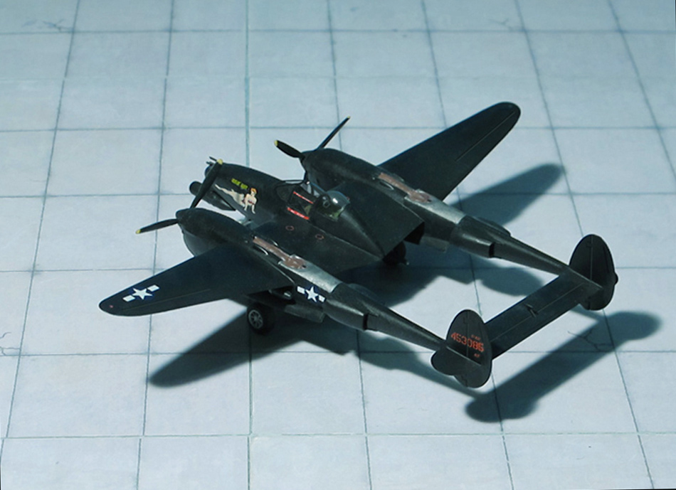
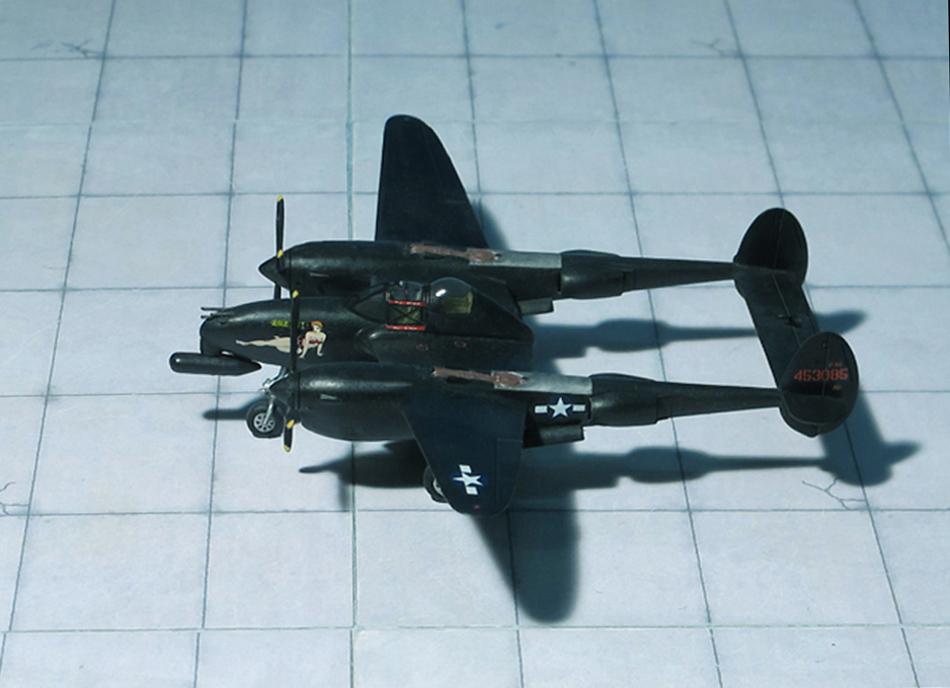
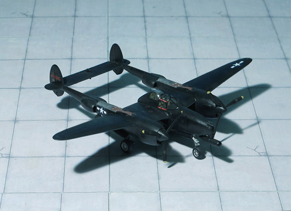
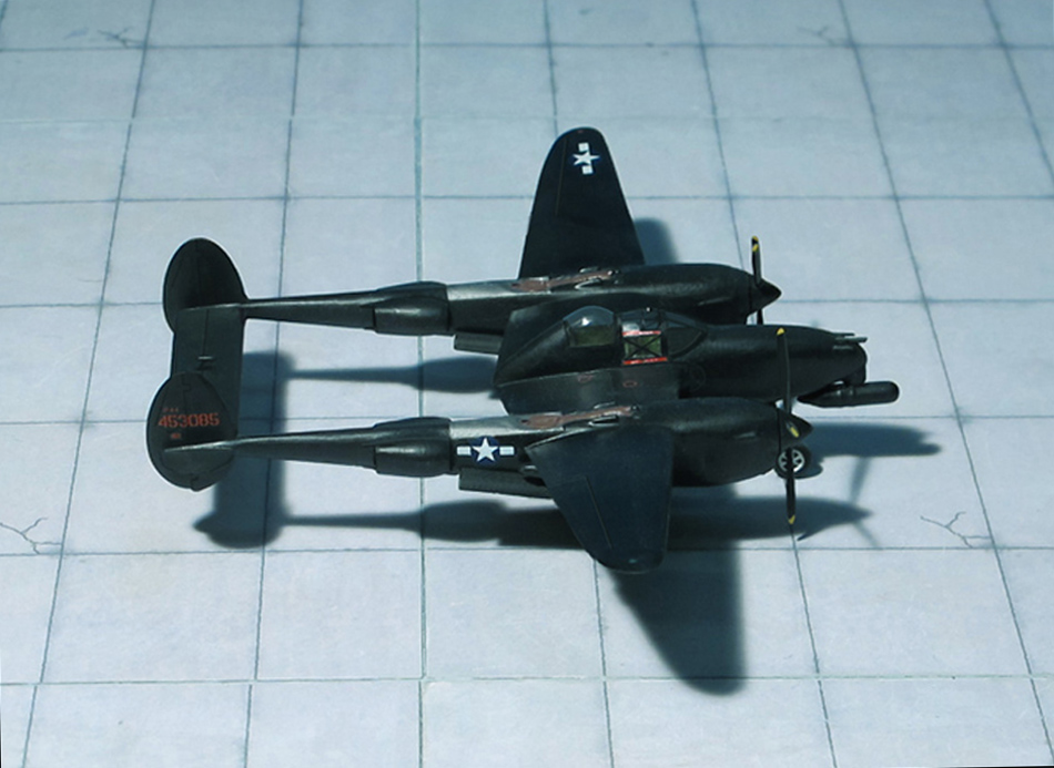
ACCOMMODATION: Crew of two, pilot and radar operator
POWER PLANT: Two Allison V-1710-111/113 liquid-cooled turbo-supercharged engines, rated at 1,600 hp each
PERFORMANCE: 410 mph at 25,000 ft
COMMENT: The Lockheed P-38 „Lightning“ is a World War II–era American piston-engined fighter aircraft. Developed for the United Stated Army Air Corps, the P-38 had distinctive twin booms and a central nacelle containing the cockpit and armament. Allied propaganda claimed it had been nicknamed the fork-tailed devil (German:„Gabelschwanz-Teufel“) by the Luftwaffe and „two planes, one pilot” by the Japanese. The Lockheed P-38 Lightning was used for aerial combat of every sort including interception, dive bombing, level bombing, ground attack, night fighting, photo reconnaissance, radar and visual pathfinding for bombers and evacuation missions, and extensively as a long-range escort fighter when equipped with drop tanks under its wings.
Adaption oft he Lightning as a night fighter, to fill the gap in the USAAF inventory caused by late delivery oft he Northrop P-61 „Black Widow“, accounted fort the last-designated variant oft he Lockheed twin, the P-38M, although the use of Lightnings in nocturnal role actually originated at squadron level rather than as a factory-designed innovation. Detachments oft he 6th Fighter Squadron flying Douglas P-70s in New Guinea and at Guadalcanal, both operated P-38Gs in this role, and the New Guinea detachment actually converted two Lightnings to two-seatres, carrying SCR-540 radar in a drop tank; the unit was, however, disbanded before these aircraft could be tested in combat. Unmodified P-38Gs and P-38Js were used as night fighters in New Guinea and on Guadalcanal with a few successful interceptions recorded.Two single seat P-38Js fitted with APS-4 radar were used with a degeree of sucess by the 547th Night Fighter Squadron operating in the Philippines in late 1944/early 1945.
While these operational innovations had been going on, a P-38J had been adapted at Wright Field to serve as a test-bed for AN/APS-4 radar, installed in the first instance in a pod under the fuselage behind the nose wheel. As it was struck by cartridges ejected when the nose gund were fired, this pod was later moved to an underwing position, outboard oft the starboard engine. Several similar radar conversions of P-38Js, including „piggy back“ two seaters were than made fort the 481st NF Operational Training group, which conducted field trials, and when the USAAF then contracted with Lockheed, in late 1944, to convert a P-38L as a night fighter, carrying a radar operator in a second cockpit behind and above the pilot, and an AN/APS-6 radar in a long pod under the nose ahead oft he nosewheel doors. The headroom in the rear cockpit was limited, requiring radar operators who were preferably short in stature.
The first flight with all modifications in place was made on February 1945, and although only six flights were made before this aircraft was destroyed, the USAAF then ordered 75 similar P-38L conversions, to be redisignated Lockheed P-38M „Night Lightning“. Testing oft he first P-38M began in July 1945, and five of these aircraft arrived at a training establishment at Hammer Field, Ca, in the same month. Found to have a better overall performance than the Northrop P-61B „Black Widow“ but to suffer some operational limitations, the P-38M saw some combat duty in the Pacific towards the end of WW II but none engaged in combat (Ref.: 9, 24).
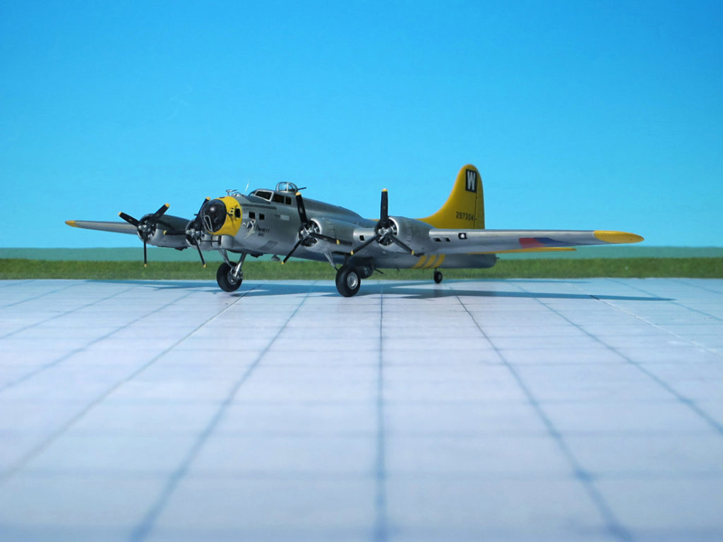
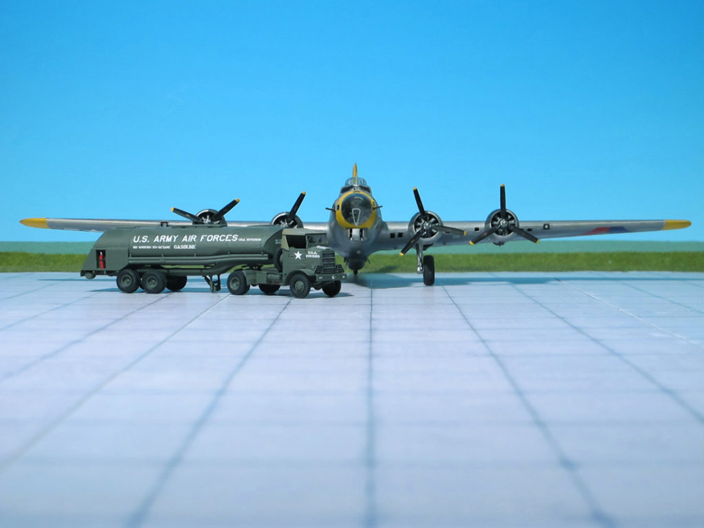
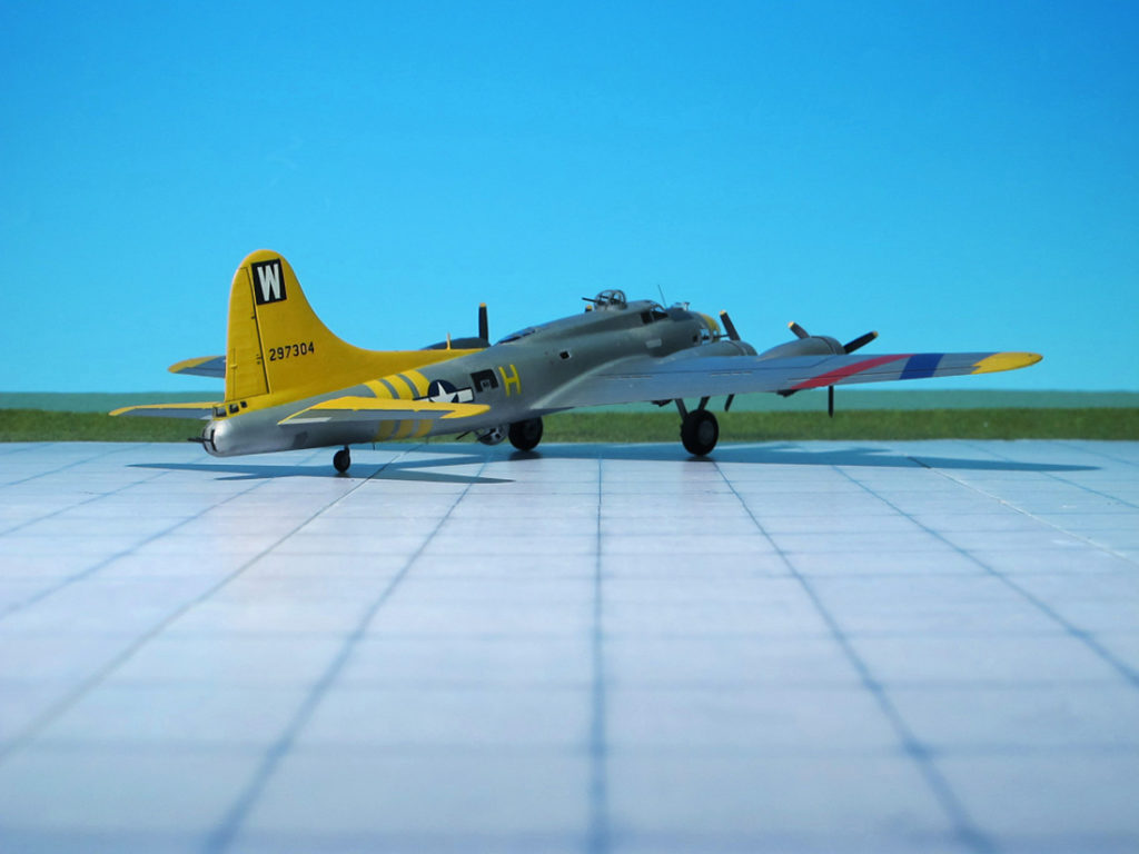
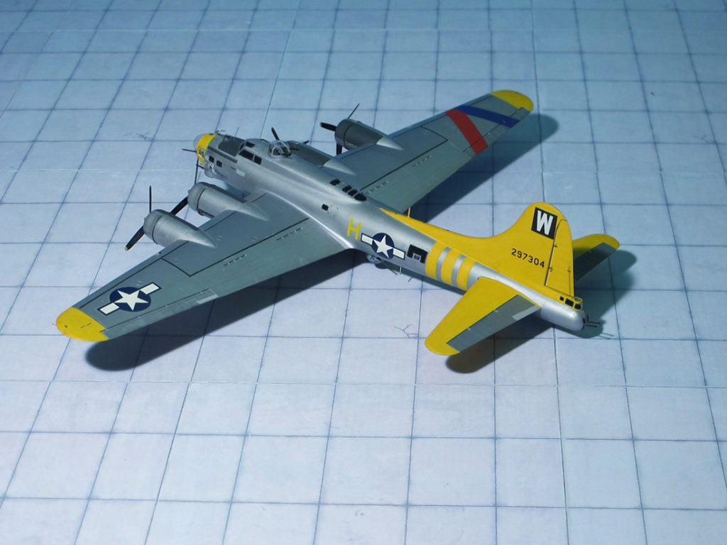
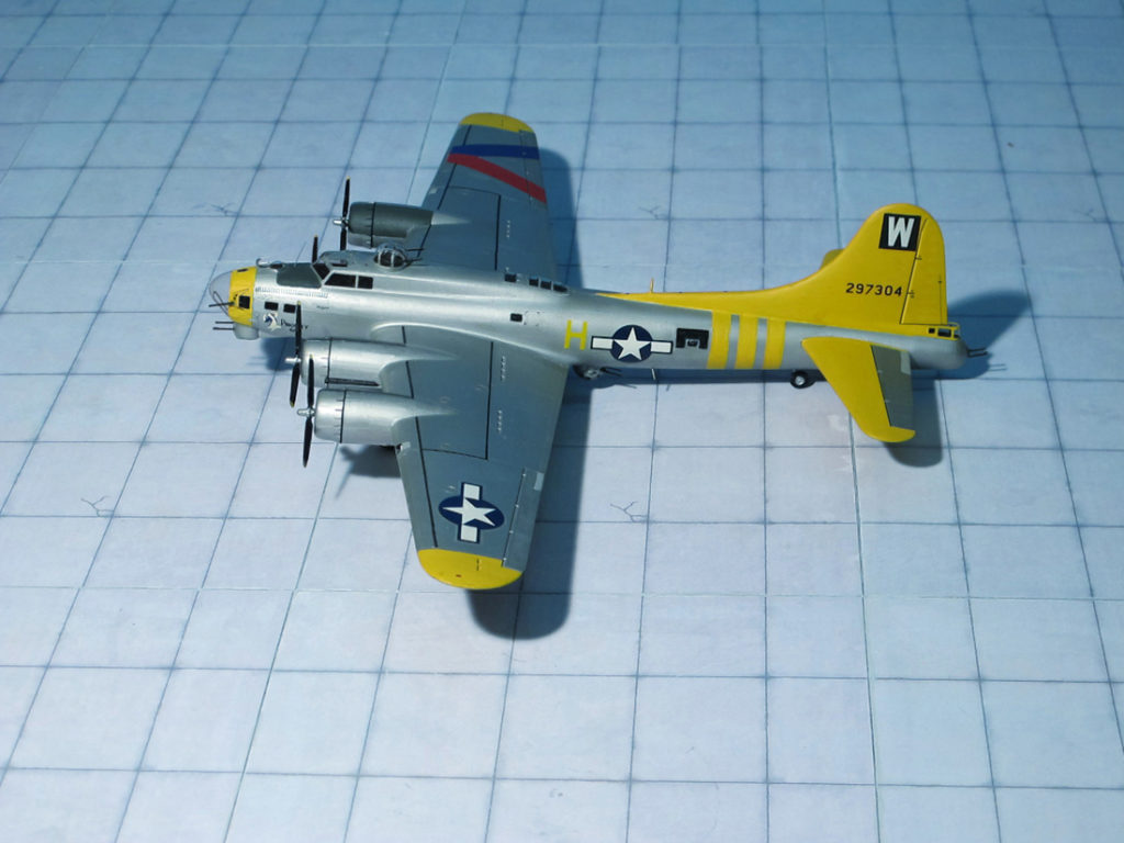
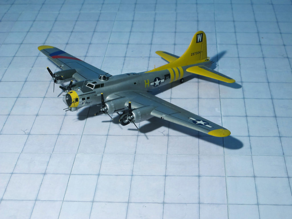
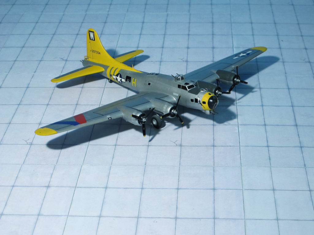
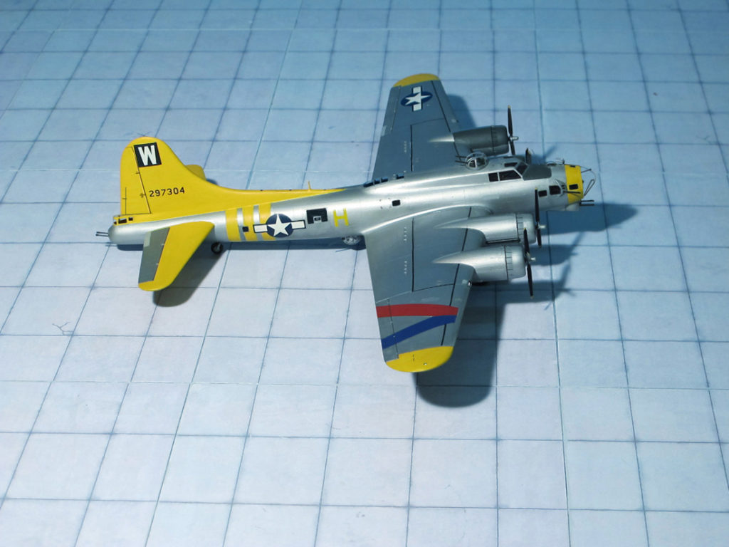
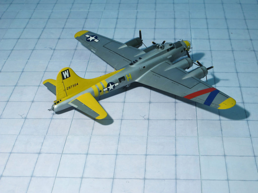
POWER PLANT: Four Wright R-1820-97 “Cyclone” turbo-supercharged radial engines, rated at 1,200 hp each
PERFORMANCE: 300 mph at 30,000 ft
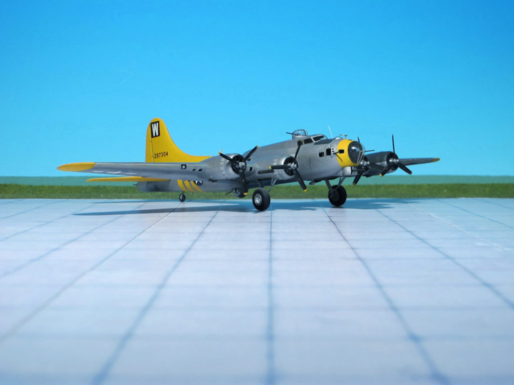
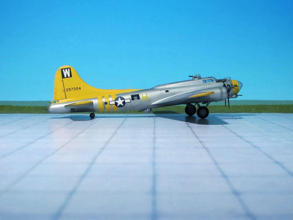
COMMENT: The Boeing B-17 Flying Fortress is a four-engine heavy bomber developed in the 1930s for the United States Army Air Corps (USAAC). From its introduction in 1938, the B-17 Flying Fortress evolved through numerous design advances becoming the third-most produced bomber of all time, behind the four-engine Consolidated B-24 Liberator and the multirole, twin-engine Junkers Ju 88,
The Boeing B-17 began operations in World War II with the Royal Air Force (RAF) in 1941, and in the Southwest Pacific with the U.S. Army. In July 1942, the first USAAF Boeing B-17Fs were sent to England to join the Eighth Air Force. Later that year, two groups moved to Algeria to join Twelfth Air Force for operations in North Africa. The B-17Fs were primarily involved in the daylight precision strategic bombing campaign against German targets ranging from U-boat pens, docks, warehouses, and airfields to industrial targets such as aircraft factories. In the campaign against German aircraft forces in preparation for the invasion of France, B-17 and B-24 raids were directed against German aircraft production while their presence drew the Luftwaffe fighters into battle with Allied fighters.
Soon, Boeing B-17Fs proved to be unsuitable for combat use over Europe. The defense expected from bombers operating in close formation alone did not prove effective and the bombers needed fighter escorts to operate successfully. Especially the head-on attacks of German fighters were dangerous, To improve defense a modification in form of a power-operated Bendix “chin” turret mounting two 0.5-in. machine guns was introduced in the last production model, the Boeing B-17G. With the two “cheek” guns and the “chin” turret the protection against incoming fighters was increased enormously. In order to improve the field of fire to the rear a so-called “Cheyenne” tail gun mounting was fitted bringing the total number of guns from seven (B-17F) to 13 (B-17G). Incorporating all changes made to its predecessor, in total 8,680 B-17Gs were built, the last (by Lockheed) on July1945.
During World War II, the B-17 equipped 32 overseas combat groups, inventory peaking in August 1944 at 4,574 USAAF aircraft worldwide (Ref.: 24).
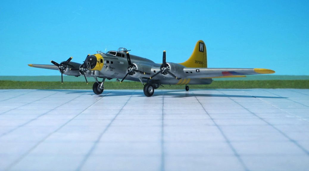
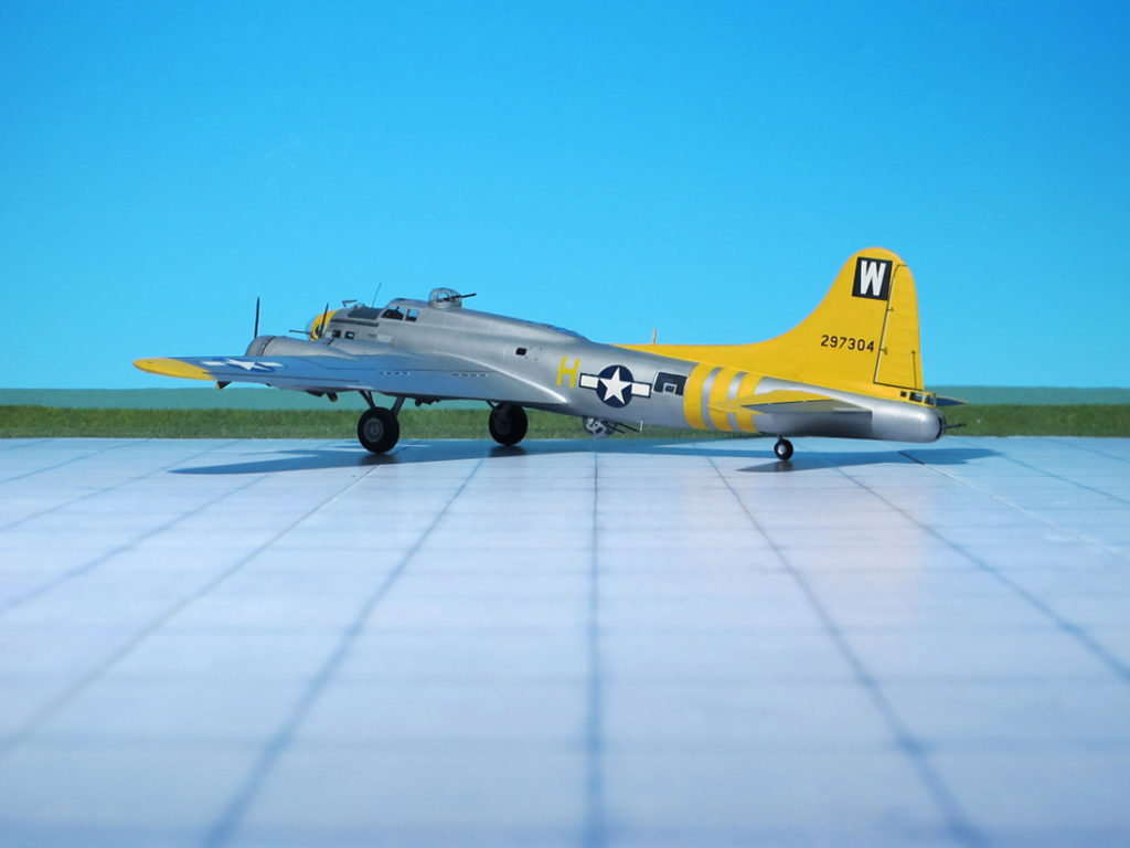
The aircraft shown here belonged to the 486th Bombardment Group (H), 832BS (Bombardment Squadron) stationed at Sudbury, UK. All B-17Gs were in natural metal. Group markings: W in square. In late 1944 red and blue bands forming chevron were painted on wing with blue band towards tip. From January 1945 wing tips and complete tail section painted yellow and three parallel bands of yellow round rear fuselage. In place nose bands and aircraft letter on fuselage (forward national insignia) in squadron color: 832BS in yellow, 833BS in medium blue, 834BS in red, and 835BS in bright green (Ref.: 2).
Boeing B-17G “Flying Fortress”, “Priority Gal”, 486 BG, 8th USAAF
Boeing B-17G “Flying Fortress”, “Priority Gal”, 486 BG, 8th USAAF
Boeing B-17G “Flying Fortress”, “Priority Gal”, 486 BG, 8th USAAF
Boeing B-17G “Flying Fortress”, “Priority Gal”, 486 BG, 8th USAAF
Boeing B-17G “Flying Fortress”, “Priority Gal”, 486 BG, 8th USAAF
Boeing B-17G “Flying Fortress”, “Priority Gal”, 486 BG, 8th USAAF
Boeing B-17G “Flying Fortress”, “Priority Gal”, 486 BG, 8th USAAF
Boeing B-17G “Flying Fortress”, “Priority Gal”, 486 BG, 8th USAAF
Boeing B-17G “Flying Fortress”, “Priority Gal”, 486 BG, 8th USAAF
Boeing B-17G “Flying Fortress”, “Priority Gal”, 486 BG, 8th USAAF
Boeing B-17G “Flying Fortress”, “Priority Gal”, 486 BG, 8th USAAF
Boeing B-17G “Flying Fortress”, “Priority Gal”, 486 BG, 8th USAAF
Boeing B-17G “Flying Fortress”, “Priority Gal”, 486 BG, 8th USAAF
Scale 1:72 aircraft models of World War II
Mit der weiteren Nutzung unserer Webseite erklären Sie sich damit einverstanden, dass wir Cookies verwenden um Ihnen die Nutzerfreundlichkeit dieser Webseite zu verbessern. Weitere Informationen zum Datenschutz finden Sie in unserer Datenschutzerklärung.