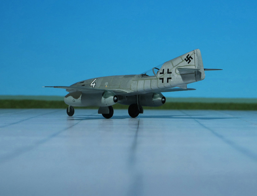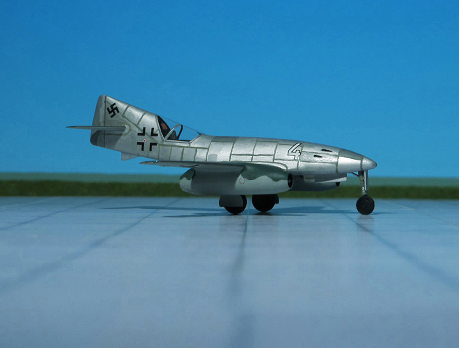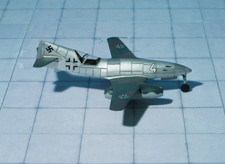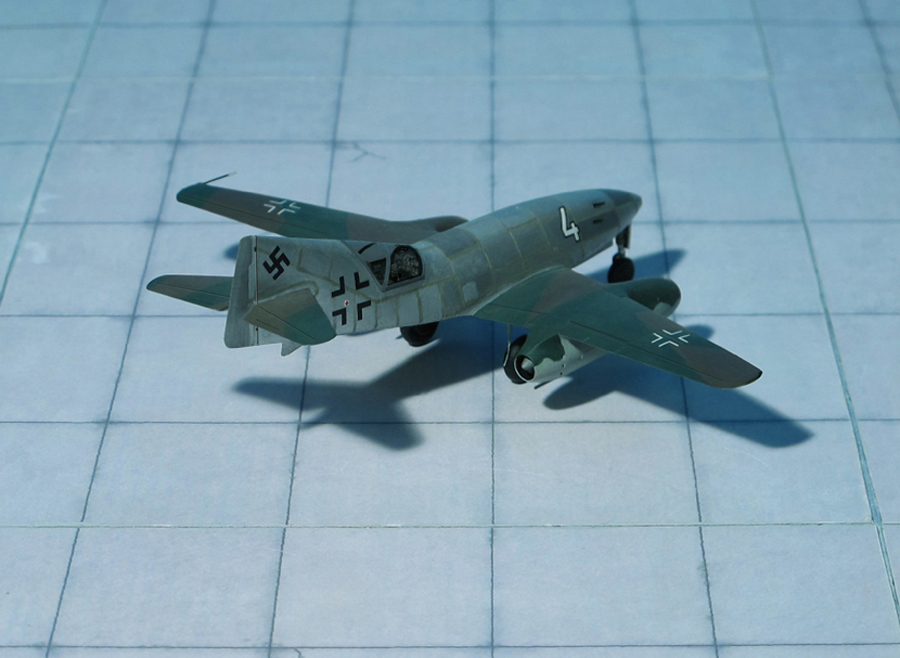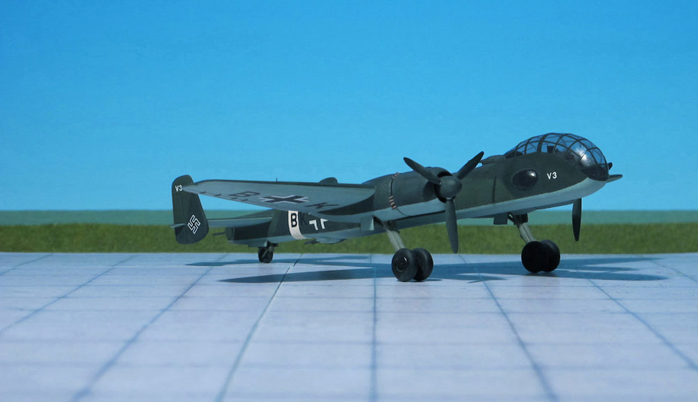
TYPE: Medium bomber
ACCOMMODATION: Crew of three
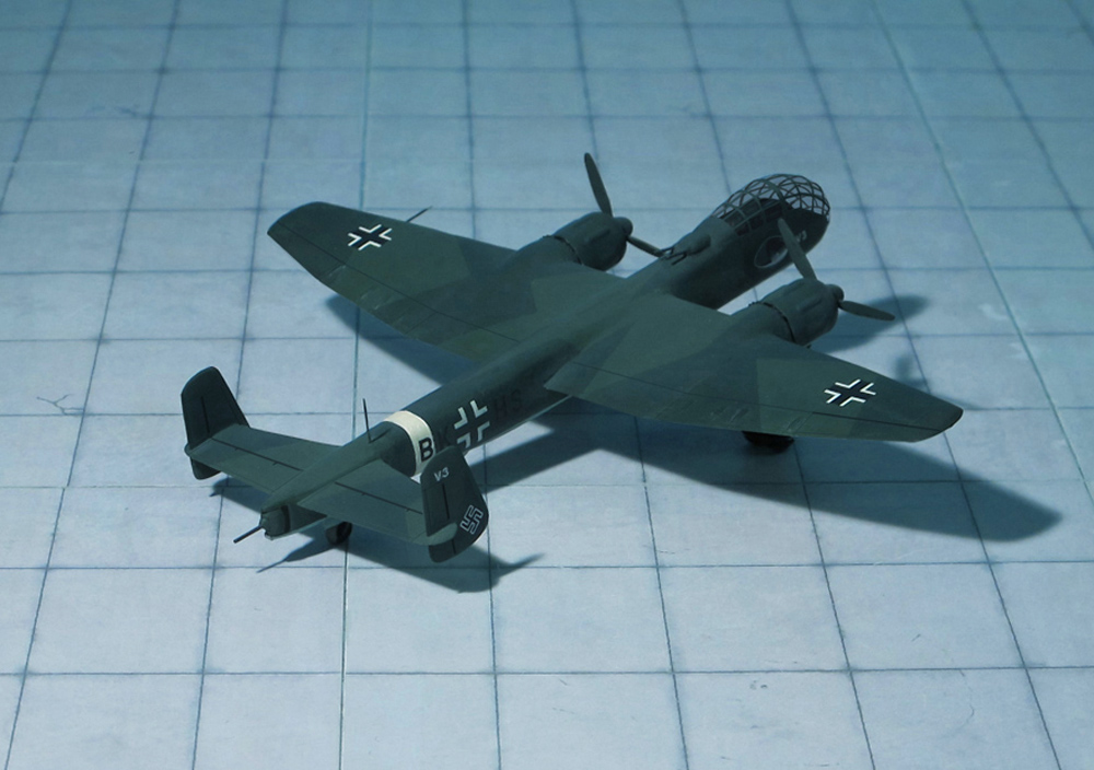
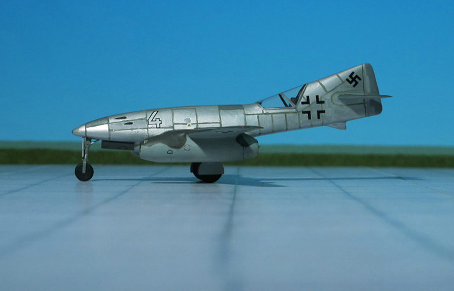
POWER PLANT: Two BMW 801MA radial engines, rated at 1,677 hp each
PERFORMANCE: 388 mph
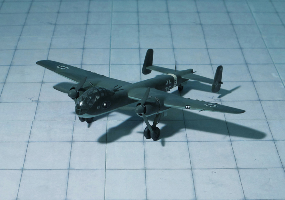
COMMENT: The Junkers Ju 288, originally known within the Junkers Company as the EF 074, was a German bomber project designed during WW II, which only ever flew in prototype form. The first of an eventual 22 development aircraft flew on 29 November 1940.
The Ju 288 was the winner of the “Bomber B” contest, although the contest was started by Junker’s submission of the EF 074 and their selection was never really in doubt. “Bomber B” intended to replace the Junkers Ju 88 with a design that was larger, offer cabin pressurization for high altitude work, have longer range, a much greater war load, be even faster, and have improved defensive firepower. The design would replace all the bombers then in German Luftwaffe service.
Delivering all of these requirements in a single airframe demanded much more powerful engines, and all of the “Bomber B” concepts relied on the Junkers Jumo 222 engine to deliver this power. Ultimately, the Jumo 222 was a failure in spite of massive effort and several redesigns over a period of several years. No suitable replacement was ever forthcoming, dooming the Ju 288 program, and leaving the Luftwaffe with older bomber designs during the second half of World War II.
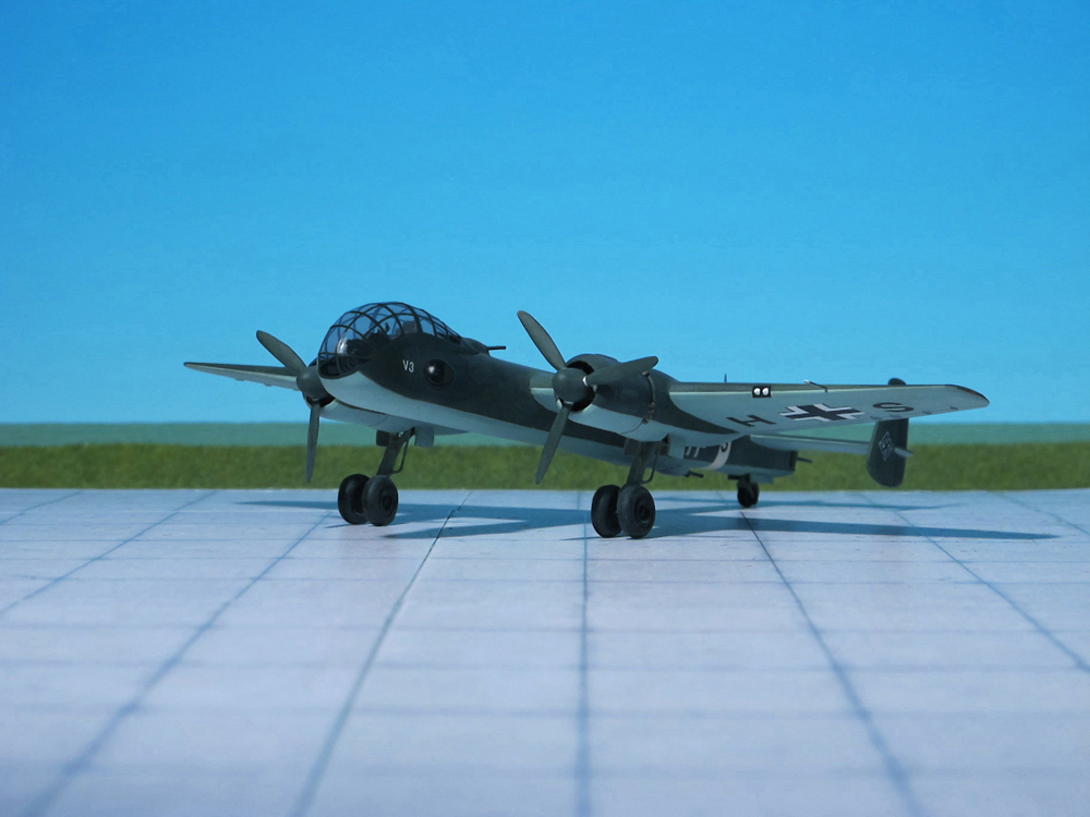
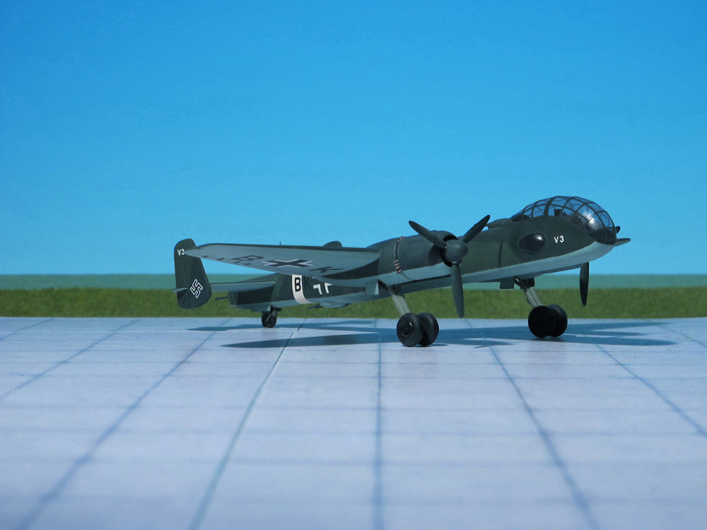
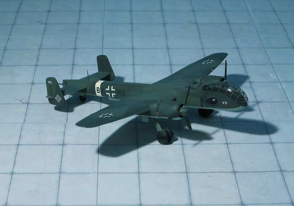
Junkers had been outlining a variety of improved models of the Ju 88 since 1937, powered by the planned Jumo 222 multibank engine, or Jumo 223 inline multibank diesel of greatly increased power of at 2,000 horsepower. The EF 074 was essentially a scaled-up Ju 88, sharing its general layout and most of its fuselage and wings with extensions in various places. The nose was redesigned with a more streamlined “stepless” cockpit, having no separate windscreen panels for the pilot and co-pilot. This layout allowed cabin pressurization to be more easily implemented. This design approach had been growing in favour, subsequently appearing in various German types, notably the Heinkel He 111P and H’s.
No serious work was undertaken on these versions, but after Heinrich Hertel left Heinkel and joined Junkers in 1939, the EF 074 design was submitted to the RLM in May 1939. Accordingly, the RLM sent out the specifications for the “Bomber B” design competition in July, the Ju 88 retroactively becoming the second aircraft to be designated “Bomber A”, as the June 1936 specification for the Heinkel He 177 also had that name. The “Bomber B” program aimed at replacing all of the medium bombers in the Luftwaffe inventory with a new design based on the EF.74 or something with equal performance. “Bomber B” was intended to have even better speed than the Ju 88, high-altitude cruising with a pressurized cockpit, heavier defensive armament, range allowing it to cover any point in the British Isles, and a 4,000 kg war load, double that of the earlier generation bombers. A number of companies returned proposals, but these were to some extent a formality, the EF.74 had already been selected as the winner, and of the rest of the designs submitted, only the Focke-Wulf Fw 191 and Dornier Do 317 progressed even as far as prototypes, and the Henschel Hs 130 coming under consideration as a late entrant.
Work began on building prototypes in early 1940, and the first example was completed by mid 1940. Power was supposed to be supplied by two Junkers Jumo 222 six-bank, four cylinders per bank, over 2.000 hp output class powerplants, but problems with the Jumo 222’s development — as with almost every new concept for over 2.000 hp output reciprocating aircrafts engienes then underway in the Third Reich — meant the first prototypes flew with BMW 801 radial engines, instead. The first flight-quality Jumo 222s did not arrive until October 1941, and even at this point it was clear they were nowhere near ready for full-scale production. When it became apparent the Jumo 222 was not likely to become a viable powerplant, in May 1942, Junkers proposed replacing them, for their projected Ju 288C version, with the much heavier Daimler Benz DB 606‘s instead; the same 1.5 tonne, twin-crankcase „weldet-together engines“ that Reichsmarschall Hermann Göring complained about some three months later, regarding the Heinkel He 177’s own endless powerplant troubles
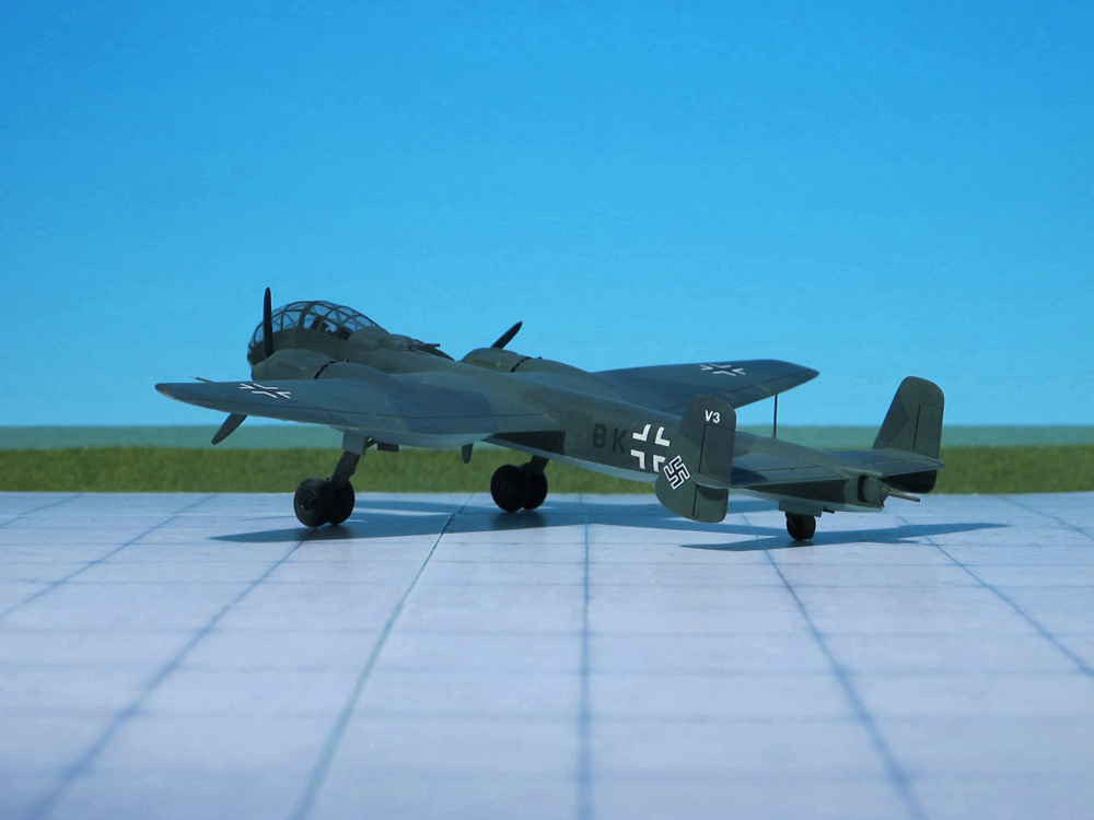
Late in January 194, after protracted ground trials, the first prototype, the Ju 288 V1, was flown for the first time. It was powered by two BMW 801 MA engines, each rated at 1,600 hp. The defensive armament arrangement reverted to that of the original EF 074 proposal, dummy barbettes being mounted in forward dorsal and aft ventral positions.
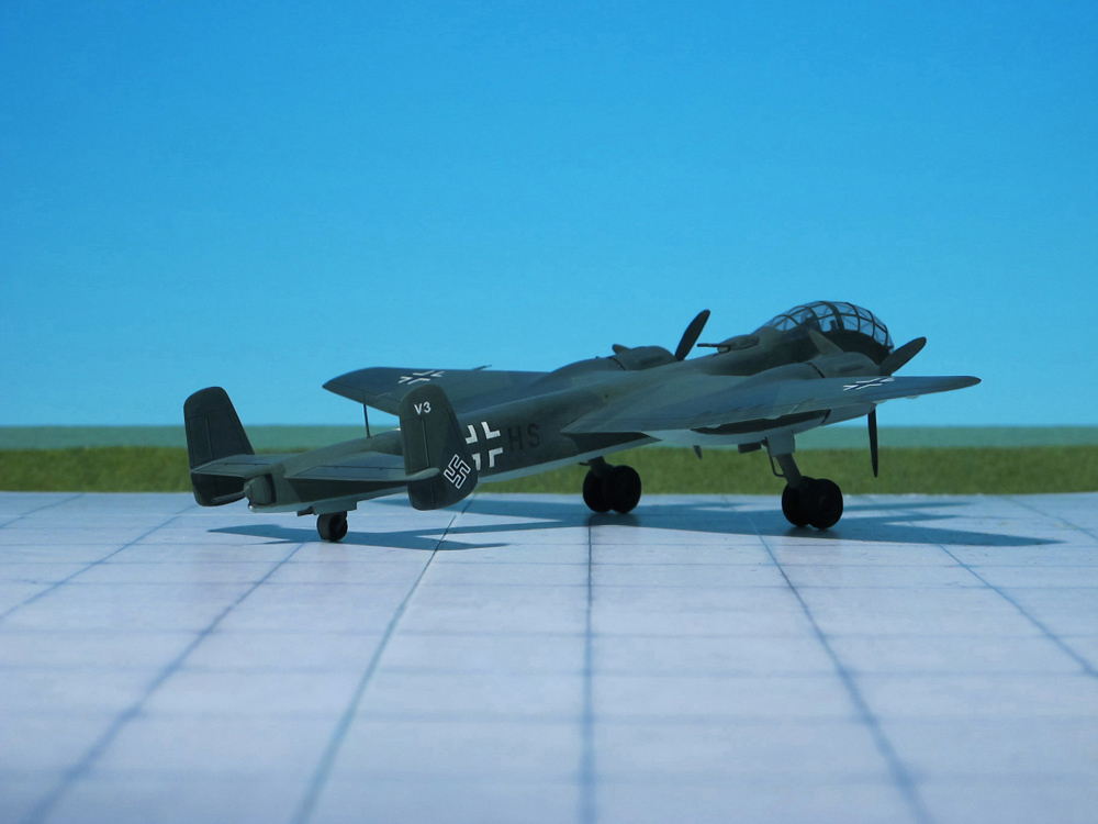
During the early spring 1941, the first prototype was joined by the Ju 288 V2 which differed from its predecessor only in having spoiler-type dive brakes in place of slatted-type surfaces which were also featured by the Ju 288 V3, this third prototype commencing flight trials during the early summer, by which time work had begun on a further series of prototypes, the first of these being the Ju 288 V4.
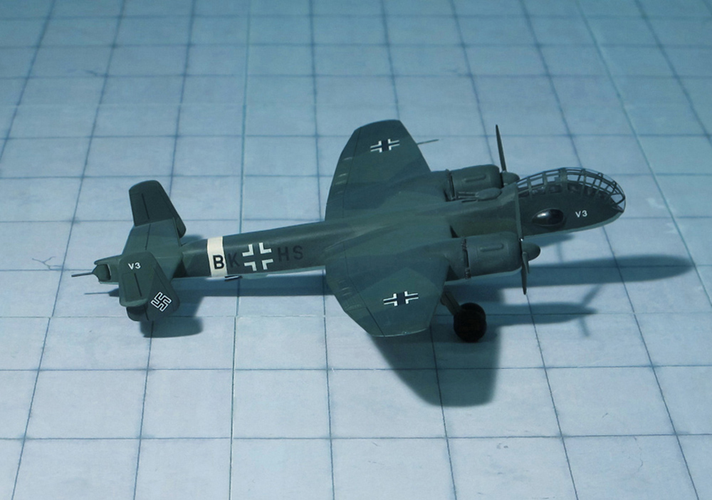
The Ju 288’s intricate main landing gear system’s design proved to be troublesome. Such a complex main gear design, with only the single pivoting retraction point for its oleo struts taking the primary stress of touchdown, was likely only one of the many potential sources of trouble causing the Ju 288’s main gear units to repeatedly collapse on touchdown.
Although the Junkers Ju 288 never even reached production status, let alone official operational service, the aircraft did see limited combat duty. In 1944, following the cancellation of the Ju 288 programme, the surviving A and C series prototypes were hurriedly fitted with defensive armament and equipment and deployed as reconnaissance bombers on the Western Front. Very few missions were flown, owing to the scarcity of aviation fuel and spare parts, and the unresolved problems with the aircraft’s power plant and undercarriage. It is believed] that the few Ju 288’s were attached to the same unit operating the small number of Junkers Ju 388 reconnaissance planes that saw service (Ref.: 7. 24).