Douglas A-26B „Invader“ (Airfix)

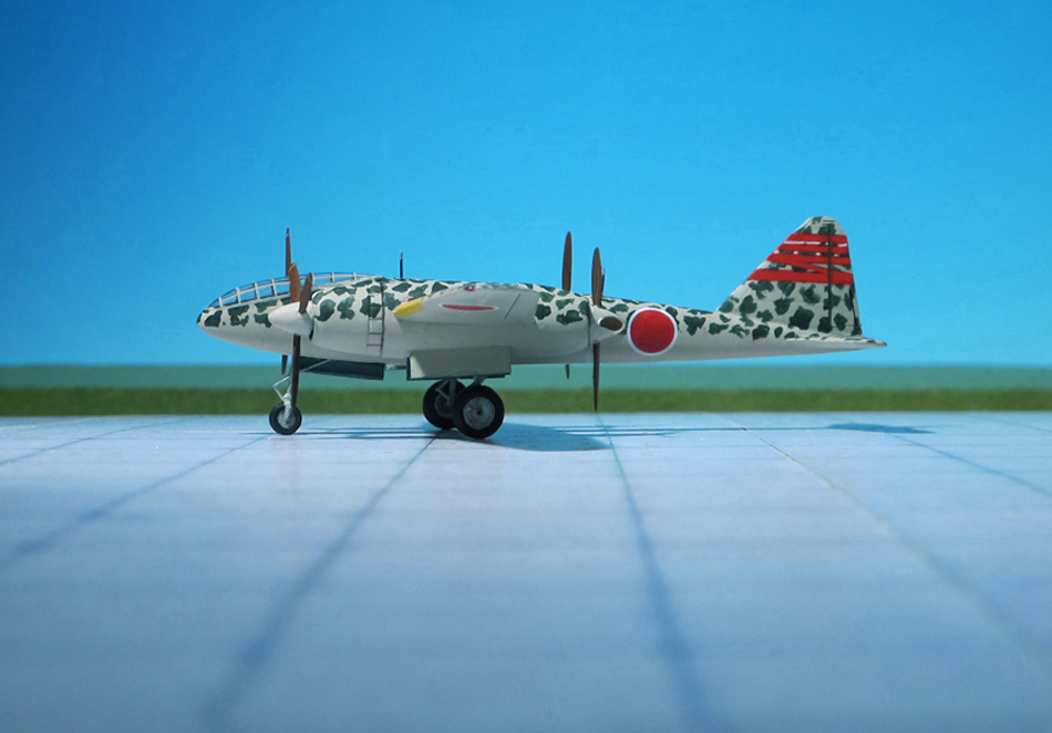
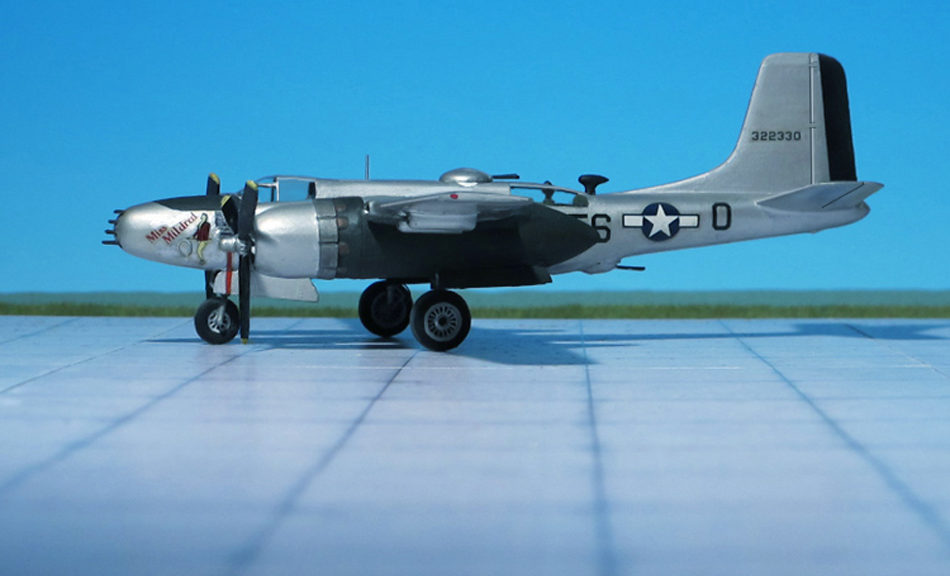
TYPE: Light bomber, ground-attack aircraft

ACCOMMODATION: Crew of three

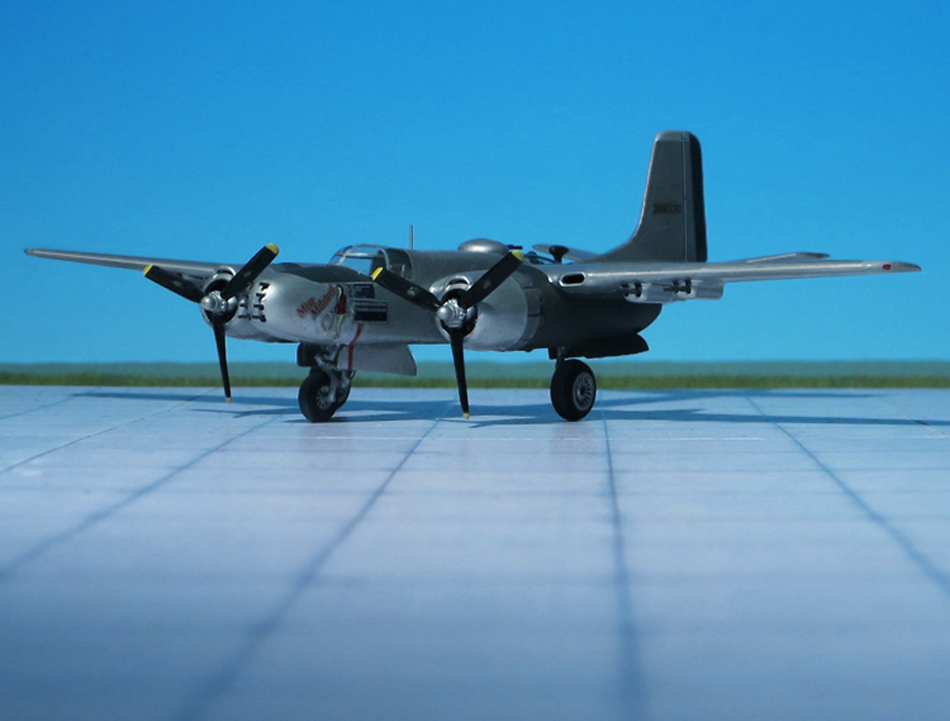
POWER PLANT: Two Pratt & Whitney R-2800-27 “Double Wasp” radial engines, rated at 2,000 hp each

PERFORMANCE: 355 mph
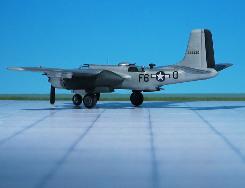
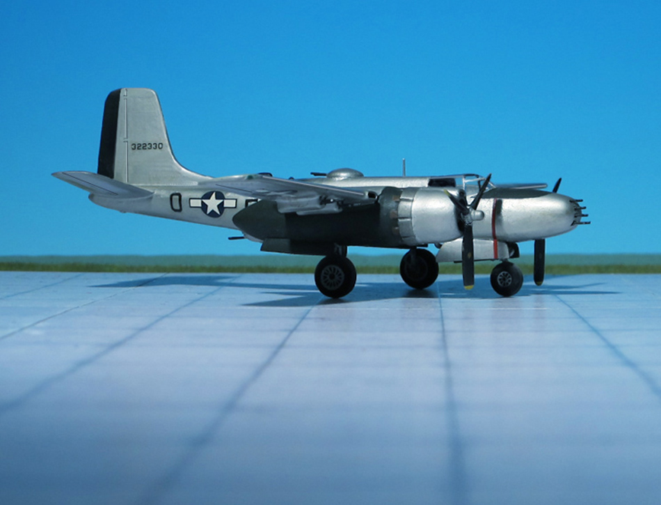
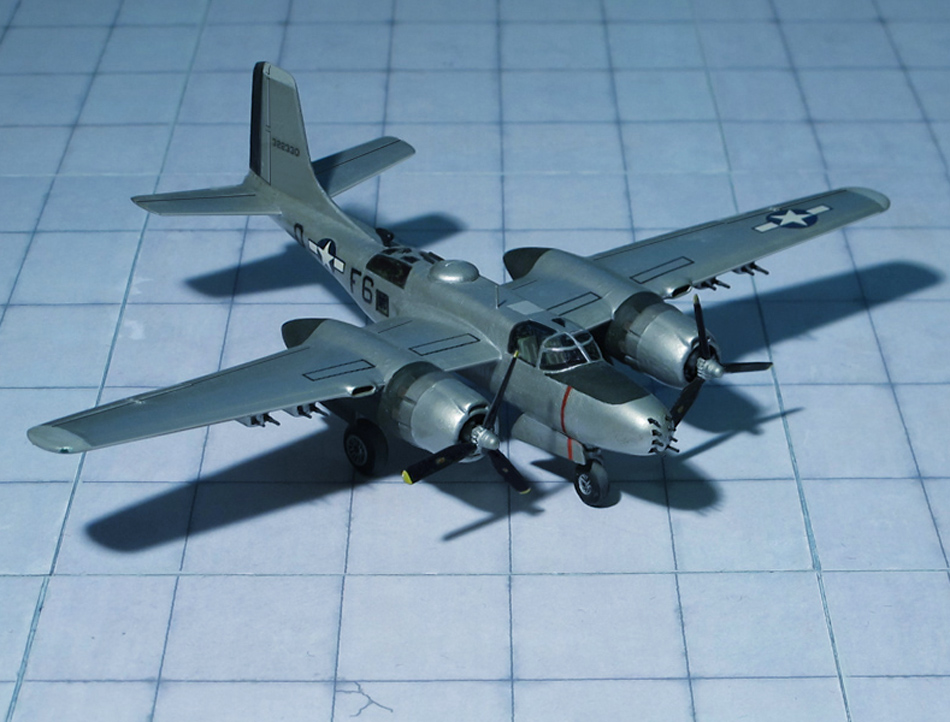
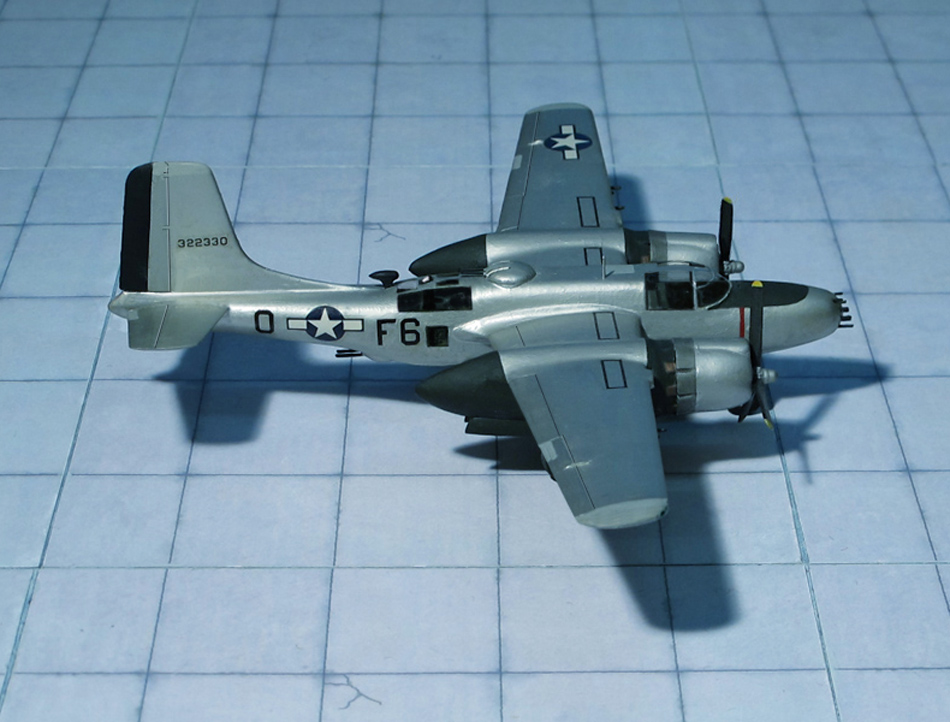

COMMENT
: The A-26 “Invader” was Douglas Aircraft’s successor to the A-20 (DB-7) “Havoc”, also known as Douglas “Boston”, one of the most successful and widely operated types flown by Allied air forces in World War II. The Douglas XA-26 prototype first flew on 10 July 1942. Flight tests revealed excellent performance and handling, but problems with engine cooling led to cowling changes and elimination of the propeller spinners on production aircraft. Repeated collapses during testing led to strengthening of the nose landing gear.
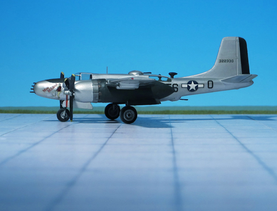
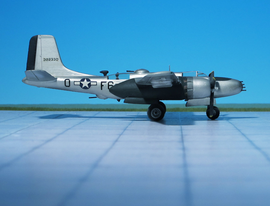
The Douglas A-26 was originally built in two different configurations. The Douglas A-26B had a gun nose, which originally could be equipped with a combination of armament including 12.7 mm machine guns, 20mm or 37mm auto cannon, or even a 75mm pack howitzer (which was never used operationally). Normally the gun nose version housed six (or later eight) .50 caliber machine guns, officially termed the “all-purpose nose”, later commonly known as the “six-gun nose” or “eight-gun nose”. The Douglas A-26C “Invader” had a glass” nose, officially termed the “Bombardier nose” and contained a Norden bombsight for medium altitude precision bombing.
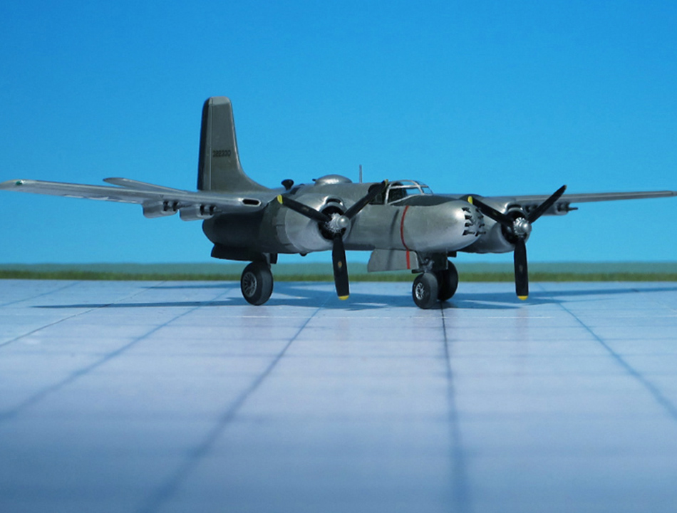
After about 1,570 production aircraft, three guns were installed in each wing, coinciding with the introduction of the “eight-gun nose” for A-26Bs, giving some configurations as many as 14 12.7 mm machine guns in a fixed forward mount. A-26C nose section could be exchanged for an A-26B nose section, or vice versa, in a few man-hours, thus physically and officially changing the designation and operational role. The “flat-topped” canopy was changed in late 1944 after about 820 production aircraft, to a clamshell style with greatly improved visibility.
Alongside the pilot in an A-26B, a crew member typically served as navigator and gun loader for the pilot-operated nose guns. A tractor-style “jump seat” was located behind the “navigator’s seat”. In most missions, a third crew member in the rear gunner’s compartment operated the remotely controlled dorsal and ventral gun turrets, with access to and from the cockpit possible via the bomb bay but only when that was empty. The gunner operated both dorsal and ventral turrets via a novel and complex (and problematic) dual-ended periscope sight, which was a vertical column running through the center of the rear compartment, with traversing and elevating/depressing periscope sights on each end. The gunner sat on a seat facing rearward, and looked into a binocular periscope sight mounted on the column, controlling the guns with a pair of handles on either side of the column. When aiming above the centerline of the aircraft, the mirror in the center of the column would flip, showing the gunner what the upper periscope was seeing. When he pressed the handles downward, as the bead passed the centerline the mirror would automatically flip, transferring the sight “seamlessly” to the lower periscope. The guns would aim wherever the periscope was aimed, automatically transferring between upper and lower turrets as required, and computing for parallax and other factors. While novel and theoretically effective, a great deal of time and trouble was spent trying to get the system to work effectively, which delayed production, and it was difficult to keep maintained in the field even once production started.
The Douglas Company began delivering the production model A-26B to the USAAF on September 1943, with the new bomber first seeing action with the Fifth Air Force in the Southwest Pacific Theater on June 1944, when Japanese-held islands near Manokwari were attacked. The pilots in the 3rd Bomb Group’s 13th Squadron, “The Grim Reapers”, who received the first four A-26s for evaluation, found the view from the cockpit to be restricted by the engines and thus inadequate for low-level attack. General George Kenney, commander of the Far East Air Forces stated that, “We do not want the A-26 under any circumstances as a replacement for anything”.
Douglas needed better results from the “Invader’s” second combat test, so A-26s began arriving in Europe in late September 1944 for assignment to the Ninth Air Force. The initial deployment involved 18 aircraft and crews assigned to the 553rd Squadron of the 386th Bomb Group. This unit flew its first mission on September 1944. No aircraft were lost on the eight test missions, and the Ninth Air Force announced that it was happy to replace all of its Douglas A-20s and Martin B-26 “Marauders” with the Douglas A-26 “Invader” (Ref.: 24).

Junkers Ju 52/3mg14e (Italeri)

TYPE: Cargo and troop transport aircraft

ACCOMMODATION: Crew of two plus 18 troop

POWER PLANT:  Three BMW 132T-2 radial engines, rated at 830 hp each

PERFORMANCE: 168 mph at 2,000 ft

COMMENT: The Junkers Ju 52/3m (nicknamed “Tante Ju”, “Aunt Ju”) was German trimotor transport aircraft manufactured in Germany from 1931 until the end of WW II. In total 4.845 aircraft have been built.
Initially designed with a single engine but subsequently produced as a trimotor, Junkers Ju 53 /3m – suffix “3m” means “Drei Motoren” (three engines) it saw both civilian and military service from mid1930 onwards.
The Ju 52 was similar to the company’s previous Junkers W 33, although larger. Designed in 1930 at the Junkers works at Dessau, Germany, the aircraft’s featured an unusual corrugated duraluminium  metal skin, pioneered by Junkers during WW I, strengthened the whole structure.
The Ju 52 had a low cantilever wing, the midsection of which was built into the fuselage, forming its underside. It was formed around four pairs of circular cross-section duralumin spars with a corrugated surface that provided torsional stiffening. A narrow control surface, with its outer section functioning as the aileron, and the inner section functioning as a flap, ran along the whole trailing edge of each wing panel, well separated from it. The inner flap section lowered the stalling speed and the arrangement became known as the “Doppelflügel” ( “double wing”).
The outer sections of this operated differentially as ailerons, projecting slightly beyond the wingtips with control horns. The strutted horizontal stabilizer carried horn-balanced elevators which again projected and showed a significant gap between them and the stabilizer, which was adjustable in-flight. All stabilizer surfaces were corrugated.
The fuselage was of rectangular section with a domed decking, all covered with corrugated light alloy. There was a port side passenger door just aft of the wings, with windows stretching forward to the pilots’ cockpit. The main undercarriage was fixed and divided; some aircraft had wheel fairings, others not. There was a fixed tailskid, or a later tailwheel. Some aircraft were fitted with floats (Junkers Ju 52/3mg5e) or skis instead of the main wheels.
Originally powered by three Pratt & Whitney R-1690 “Hornet” radial engines, later production models mainly received 770 hp BW 132 engines, a license-built refinement of the Pratt & Whitney design. The two wing-mounted radial engines of the Ju 52/3m had half-chord cowlings and in planform view (from above/below) appeared to be splayed outwards, being mounted at an almost perpendicular angle to the tapered wing’s sweptback leading edge (in a similar fashion to the Mitsubishi G3M bomber (Allied code “Betty”) and Short “Sunderland” flying boat; the angled engines on the Ju 52 were intended to make it easier to maintain straight flight should an engine fail, while the others had different reasons). The three engines had either “Townend” ring or NACA cowlings to reduce drag from the engine cylinders, although a mixture of the two was most common, with deeper-chord NACA cowlings on the wing engines and a narrow “Townend” ring on the center engine, which was more difficult to fit a deeper NACA cowl onto, due to the widening fuselage behind the engine. Production Ju 52/3m aircraft flown by Luftwaffe usually used an air-start system to turn over their trio of radial engines, using a common compressed air supply that also operated the main wheels’ brakes.
In service with Lufthansa, the Junkers Ju 52/3m had proved to be an extremely reliable passenger airplane. Therefore, it was adopted by the Luftwaffe as a standard aircraft model and flew as a troop and cargo transport.. The Luftwaffe had 552 Ju 52/3ms in service at the beginning of WW II. Even though it was built in great and production continued until approximately the summer of 1944; when the war came to an end, there were still 100 to 200 aircraft available (Ref.: 24).

Kogiken Plan VIII High-Speed Reconnaissance Aircraft, (Unicraft Models, Resin)

TYPE: Fast reconnaissance aircraft, light bomber. Project


ACCOMMODATION: Crew of three

POWER PLANT: Four Mitsubishi Ha-211-II “Kinsai” (“Venus”) radial engines, rated at 1,075 hp each

PERFORMANCE: 481 mph (estimated)

COMMENT: In early 1941, Rikugun Kokugijutsu Kenkyujo (Japanese Army Aerotechnical Research Institute)  abbreviated “Kogiken”, formed a design group in order to study Japanese aviation technology in terms of what was possible at present and in the near future.
Of several high-speed reconnaissance aircraft concepts one of the designs was the Kogiken Plan VIII High Speed Reconnaissance aircraft. Including many concepts from Kogiken’s bomber design division, the Plan VIII aircraft was distinguished by its highly aerodynamic design. The cockpit for a crew of three was located at the tip of the fuselage, giving excellent view, and the glazing was flush with the rest of the airframe. Four Mitsubishi Ha-211-II radial engines were to be housed front-to-back in two stream-lined underwing engine nacelles, driving three-bladed tractor- and pusher propellers. Alternatively the Nakajima Ha-45 “Sakae” (“Prosperity”) radial engine, rated at 1,115 hp each could be installed. A tricycle landing gear was provided. The plane had a projected top speed of 481 mph and a maximum range of 1,864 miles. Due to its high speed no armament was provided. The design drawings were completed but although the calculated performance was promising the project was not realized (Ref: 24),

Fairey 0.21/44 (Unicraft Models, Resin)

TYPE: Carrier-borne torpedo-bomber, strike fighter. Project

ACCOMMODATION: Pilot and navigator

POWER PLANT: Two twin-coupled Rolls-Royce “Merlin” RM.14.SM, rated at 2,200 hp

PERFORMANCE: 360 mph at 15,000 ft

COMMENT: In autumn 1944 the Fairey Corporation was asked to assess the feasibility of adapting its original tandem, twin engine research studies to a new naval strike platform as a replacement of the troublesome Fairey “Spearfish”. The new aircraft was planned for use aboard the new 46,000 t “Malta”-class aircraft carriers then under development and as power units two tandem-coupled engines were proposed: The Rolls-Royce “Tandem Merlin” (Project A) or alternatively the Rolls-Royce “Twin Griffon” (Project B). Either design was intended to be a single-seat aircraft, although there was the possibility for adding a rear compartment for a navigator.
During March 1945, Fairey redesigned the “Project A’s” overall specifications. The plane would still employ the Rolls-Royce “Merlin” twin-coupled power plant, but the new version was streamlined and compacted. The aircraft was a cantilever, mid-wing monoplane, with an all-metal, monocoque fuselage, the centre wing section was built integral with the fuselage and the outer wing panels could be hydraulically folded for carrier operations. It had an internal weapons bay to hold a torpedo, retractable ASV Mk. XV surface search radar mounted behind the bomb bay, contra-rotating propellers, and a stronger outward retracting conventional landing gear with a tailwheel.  The cockpit was positioned high above the engine and offered an excellent view for the pilot, the navigators position was behind the cockpit in a separate copula operating a remote-controlled Frazer-Nash FN 95 barbette holding two 12,7 mm M2 Browning machine guns.
With the end of WW II and the upcoming turbojet- and turboprop-engines as well as the cancellation of all orders for new “Malta”-class aircraft carriers the Fairey design was abandoned. Nevertheless, in the post-war period this design influenced the development of the successful carrier-born anti-submarine aircraft Fairey “Gannet” (Ref.: Unicraft, 24).