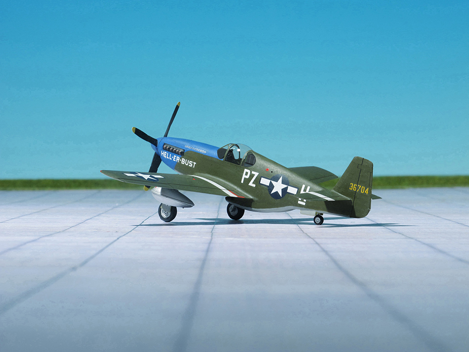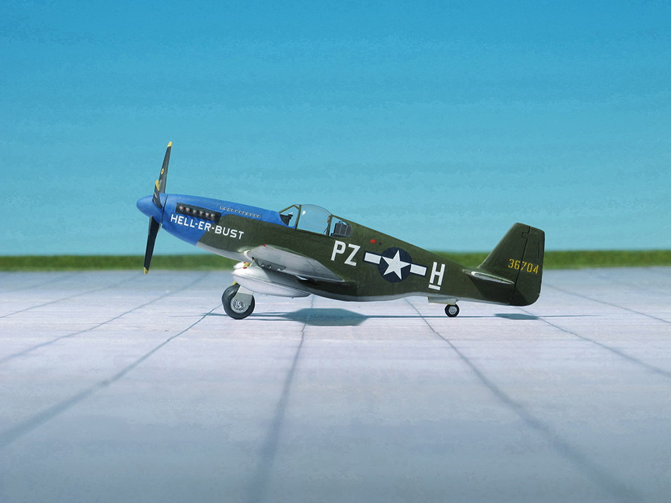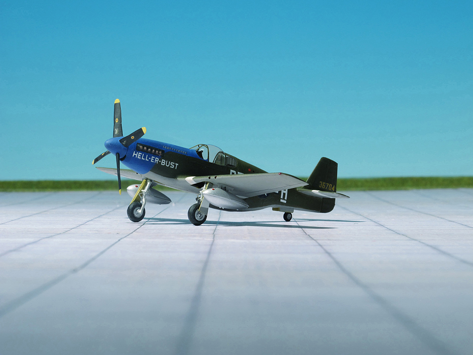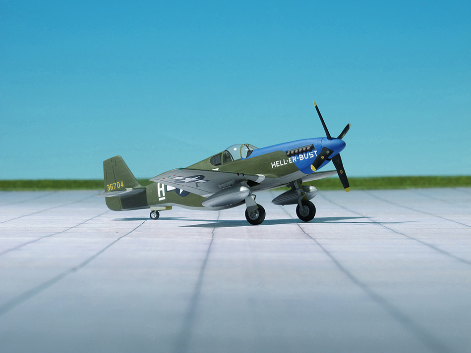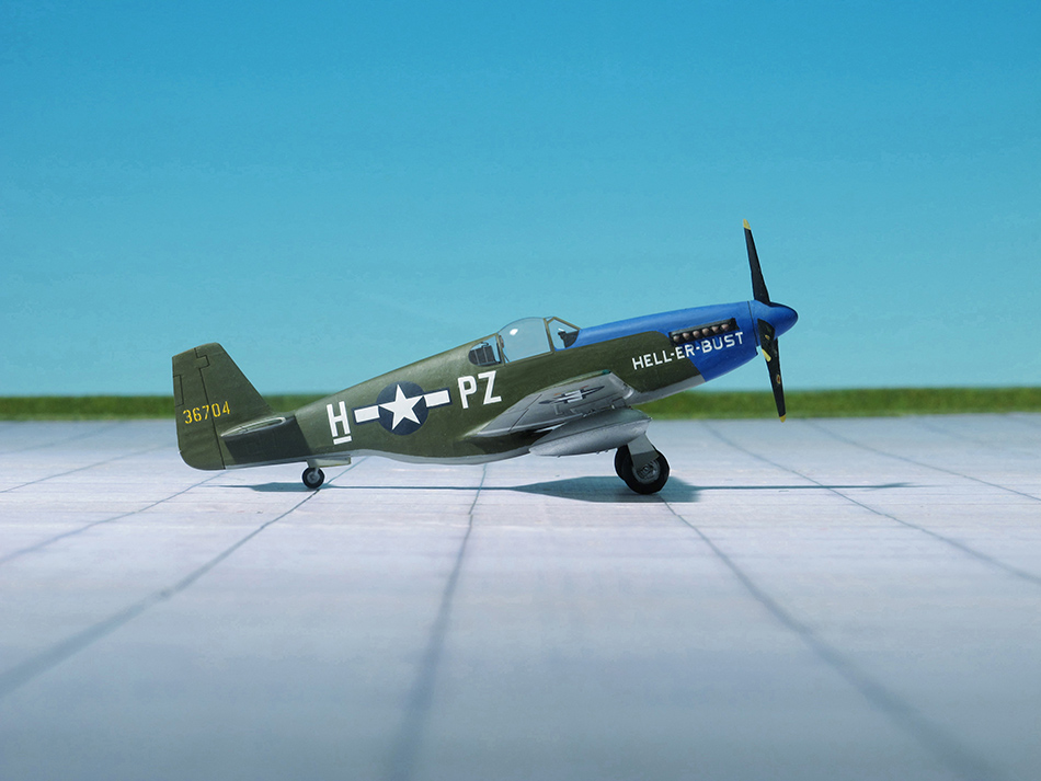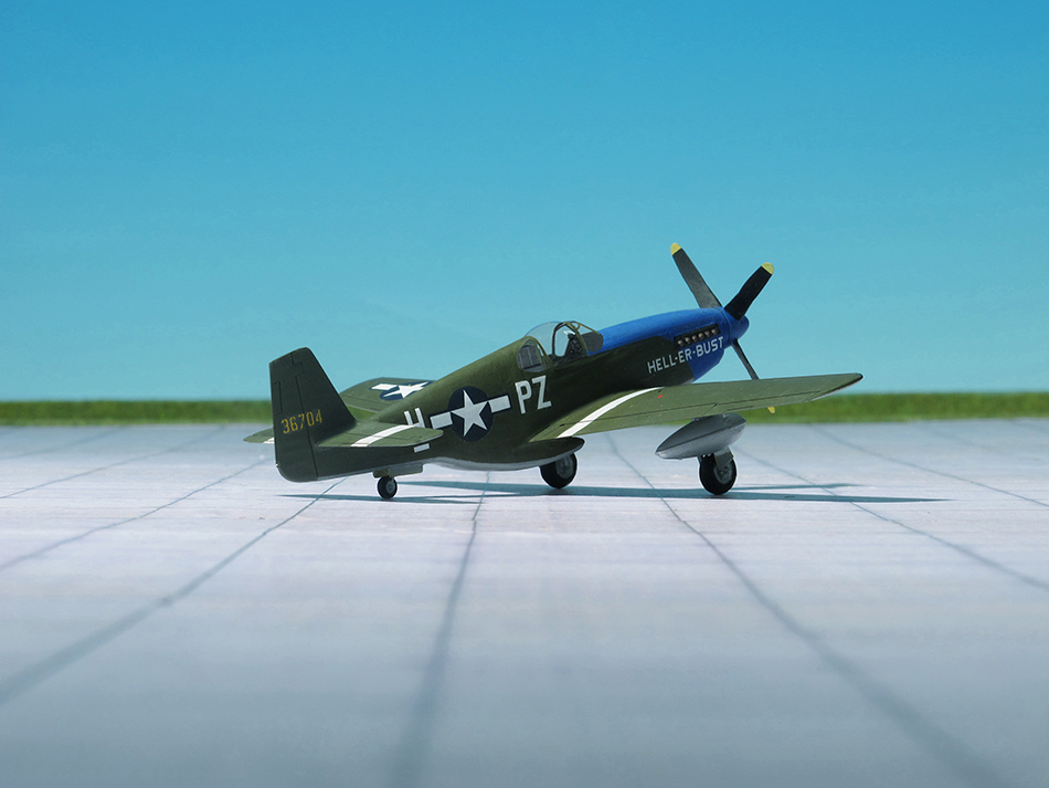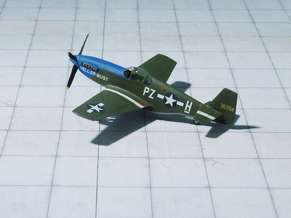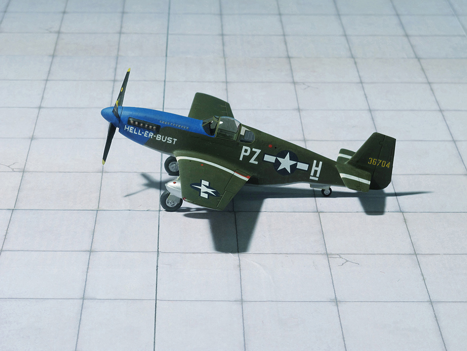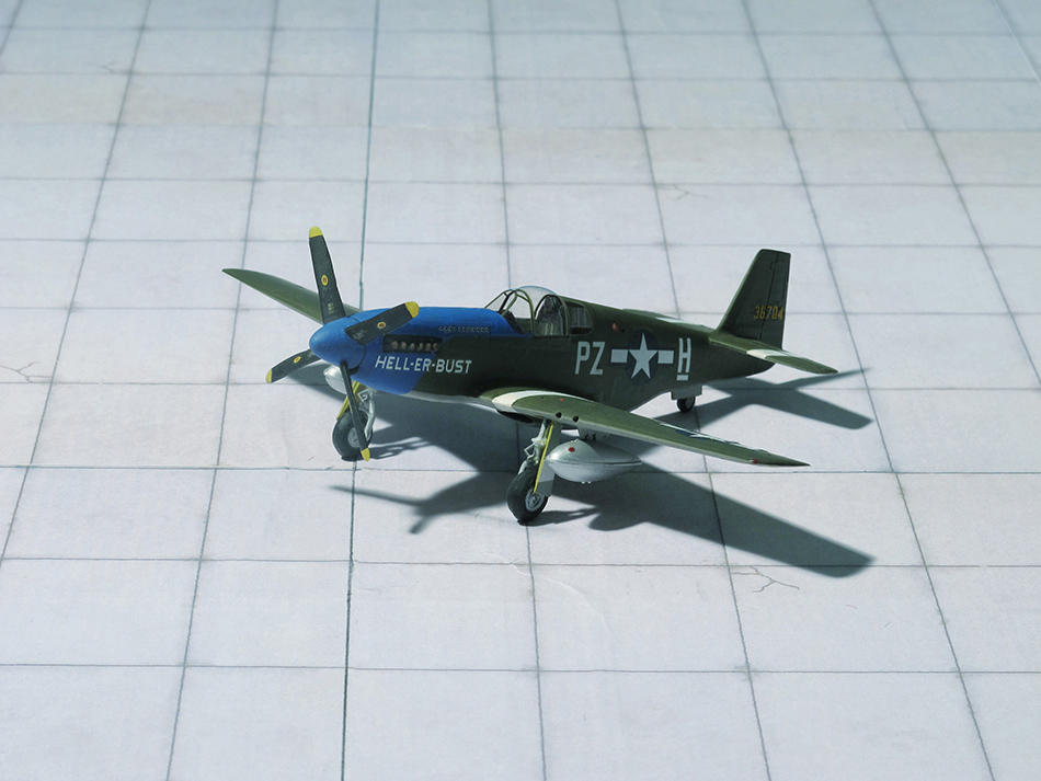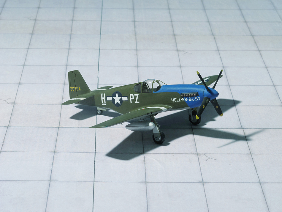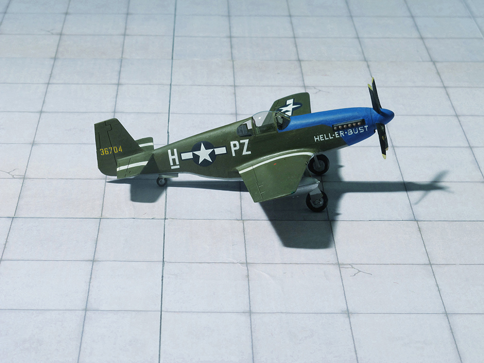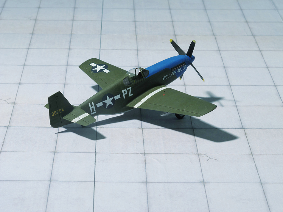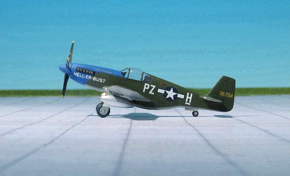
TYPE: Fighter, fighter bomber
ACCOMMODATION: Pilot only
POWER PLANT: One Packard (Rolls-Royce) V-1650-7 Merlin liquid-cooled engine, rated at 1,490 hp
PERFORMANCE: 440 mph
COMMENT: The North American Aviation P-51 Mustang was an American long-range, single-seat fighter and fighter-bomber used during World War II and other conflicts. The Mustang was designed in April 1940 by a team headed by James Kindelberger of North American Aviation (NAA) in response to a requirement of the British Purchasing Commission. The Purchasing Commission approached North Americam Aviation to build Curtiss P-40 fighters under license for the Royal Air Force (RAF). Rather than build an old design from another company, North American Aviation proposed the design and production of a more modern fighter. The prototype NA-73X airframe was rolled out on September 1940, only 102 days after the contract was signed, and first flew on 26 October.
The Mustang was designed to use the Allison V-1710 engine, which had limited high-altitude performance in its earlier variants. The aircraft was first flown operationally by the RAF as a tactical reconnaissance aircraft and fighter-bomber (Mustang Mk I). Replacing the Allison with a Rolls-Royce Merlin resulted in the P-51B/C (Mustang Mk III) model, and transformed the aircraft’s performance at altitudes above 15,000 ft without sacrificing range allowing it to compete with the Luftwaffe‘s fighters such as Messerschmitt Bf 109 and Focke-Wulf Fw 190.
From late 1943, P-51Bs and P-51Cs (supplemented by P-51Ds from mid-1944) were used by the USAAF’s Eighth Air Force to escort bombers in raids over Germany, while the RAF’s Second Tactical Air Force and the USAAF’s Ninth Air Force used the Merlin-powered Mustangs as fighter-bombers, roles in which the Mustang helped ensure Allied air superiority in 1944. The P-51 was also used by Allied air forces in the North Africa, Mediterranean, Italien, and Pacific theaters. During World War II, Mustang pilots claimed to have destroyed 4,950 enemy aircraft.
The design oft he NA-73X followed the best conventional practice of the era, designed for ease of mass manufacturing. The design included several new features. One was a wing designed using laminar flow airfoils, which were developed co-operatively by North American Aviation and the National Advisory Committy for Aeronautics (NACA). These airfoils generated low drag at high speeds. During the development of the NA-73X, a wind tunnel test of two wings, one using NACA five-digit airfoils and the other using the new NAA/NACA 45–100 airfoils, was performed in the University of Washington Kirsten Wind Tunnel. The results of this test showed the superiority of the wing designed with the NAA/NACA 45-100 airfoils.
The other feature was a new cooling arrangement positioned aft (single ducted water and oil radiators assembly) that reduced the fuselage drag and effects on the wing. Later, after much development, they discovered that the cooling assembly could take advantage of the Meredith effect: in which heated air exited the radiator with a slight amount of jet thrust. Because NAA lacked a suitable wind tunnel to test this feature, it used the GALCIT10 ft wind tunnel at the California Institute of Technology. This led to some controversy over whether the Mustang’s cooling system aerodynamics were developed by NAA’s engineers or by Curtiss, as NAA had purchased the complete set of Curtiss P-40 and Curtiss XP-46 wind tunnel data and flight test reports. The NA-73X was also one of the first aircraft to have a fuselage lofted mathematically using conic sections; this resulted in smooth, low-drag surfaces. To aid production, the airframe was divided into five main sections—forward, center, rear fuselage, and two wing halves – all of which were fitted with wiring and piping before being joined.
During flight tests the prototype handled well and accommodated an impressive fuel load. The aircraft’s three-section, semi-monocoque fuselage was constructed entirely of aluminum to save weight. It was armed with four .30 caliber AN/M2 Browning machine guns in the wings and two .50 caliber AN/M“ Browning machine guns mounted under the engine and firing through the propeller arc using gun-synchronizing gear.
While the USAAC could block any sales it considered detrimental to the interests of the US, the NA-73 was considered to be a special case because it had been designed at the behest of the British. In September 1940, a further 300 NA-73s were ordered by the MAP (Ministry of Aircraft Production). To ensure uninterrupted delivery, USAAC arranged with the Anglo-French Purchasing Commission to deliver the aircraft and NAA gave two examples (41-038 and 41-039) to the USAAC for evaluation
At the same time, the possibility of combining the P-51 airframe with the US license-built Packard version of the Merlin engine was being explored on the other side of the Atlantic. In July 1942, a contract was let for two prototypes, briefly designated XP-78, but soon to become the XP-51B. Based on the Packard V-1650-3 duplicating the Merlin 61’s performance, NAA estimated for the XP-78 a top speed of 445 mph at 28,000 ft, and a service ceiling of 42,000 ft. The first flight of the XP-51B took place in November 1942, but the USAAF was so interested in the possibility that an initial contract for 400 aircraft was placed three months beforehand in August. The conversion led to production of the P-51B beginning at North American’s Inglewood, California, plant in June 1943, and P-51Bs started to become available to the 8th and 9th Air Forces in the winter of 1943–1944. Conversion to the two-stage supercharged Merlin 61, over 350 lb heavier than the single-stage Allison, driving a four-bladed Hamilton Standard propeller, required moving the wing slightly forward to correct the aircraft’s center of gravity. After the USAAF, in July 1943, directed fighter aircraft manufacturers to maximize internal fuel capacity, NAA calculated the P-51B’s center of gravity to be forward enough to include an additional 85 US gal uel tank in the fuselage behind the pilot, greatly increasing the aircraft’s range over that of the earlier P-51A. NAA incorporated the tank in the production of the P-51B-10, and supplied kits to retrofit it to all existing P-51B.
One of the few remaining complaints with the Merlin-powered aircraft was a poor rearward view. The canopy structure, which was the same as the Allison-engined Mustangs, was made up of flat, framed panels; the pilot entered or exited the cockpit by lowering the port side panel and raising the top panel to the right. The canopy could not be opened in flight and tall pilots especially were hampered by limited headroom. In order to at least partially improve the view from the Mustang, the British had field-modified some Mustangs with clear, sliding canopies called Malcolm hoods designed by R. Malcolm & Co), and whose design had also been adopted by the U.S. Navy’s own F4U-1D version of the Vought F4U Corsair in April 1944.
The new structure was a frameless plexiglas moulding which ballooned outwards at the top and sides, increasing the headroom and allowing increased visibility to the sides and rear. Because the new structure slid backward on runners, it could be slid open in flight. The aerial mast behind the canopy was replaced by a “whip” aerial which was mounted further aft and offset to the right. Most British Mk IIIs were equipped with Malcolm hoods. Several American service groups “acquired” the necessary conversion kits and some American P-51B/P-51Cs appeared with the new canopy, although the majority continued to use the original framed canopies.
Allied strategists quickly exploited the long-range fighter as a bomber escort. It was largely due to the P-51 that daylight bombing raids deep into German territory became possible without prohibitive bomber losses in late 1943.
1,987 P-51B-NA were built at Inglewood, California and 1,750 identical P-51C-NT were bult at built at Inglewood, California.
A number of the P-51B and P-51C aircraft were fitted for photo reconnaissance and designated F-6C (Ref.: 24).